
Related Manuals for Kramer 914


Summary of Contents for Kramer 914
-
Page 1: User Manual
K R A ME R E LE CT R O N IC S L TD . USER MANUAL MODEL: Power Amplifier P/N: 2900-300280 Rev 1... -
Page 3: Table Of Contents
Figure 1: 914 Power Amplifier Front Panel Figure 2: 914 Power Amplifier Rear Panel Figure 3: Connecting the 914 Power Amplifier Figure 4: Connecting Remote Control Switches to the 914 Figure 5: Connecting Speakers to the 914 Power Amplifier Figure 6: Balanced Stereo Audio Connection Figure 7: Unbalanced Stereo Audio Input Connection 914 –... -
Page 4: Introduction
GROUP 9: Room Connectivity; GROUP 10: Accessories and Rack Adapters and GROUP 11: Sierra Products; GROUP 12: Digital Signage; and GROUP 13: Audio, and GROUP 14: Collaboration. Congratulations on purchasing your Kramer 914 Power Amplifier, which is ideal for the following typical applications: ... -
Page 5: Getting Started
Avoid interference from neighboring electrical appliances that may adversely influence signal quality Position your Kramer 914 away from moisture, excessive sunlight and dust This equipment is to be used only inside a building. It may only be connected to other equipment that is installed inside a building. -
Page 6: Overview
To comply with the Energy Star requirements the 914 provides the following operational modes: 1. On Mode—Where the 914 is connected to a mains power source, has been activated and is capable of providing amplification. The common terms “active”, “in-use” and “normal operation” also describe this mode. - Page 7 2. Standby Mode—where the 914 is connected to a mains power source, is incapable of providing amplification, and offers the following user oriented or protective functions: It facilitates the activation of other modes (including activation of On Mode) by a remote switch (including remote, contact-closure switches), and timer ...
-
Page 8: Defining The 914 Power Amplifier
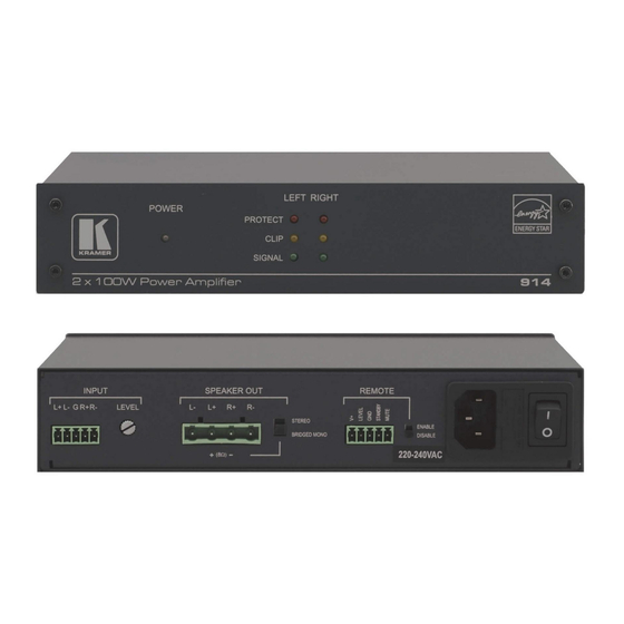
Defining the 914 Power Amplifier Figure 1 defines the front panel of the 914 Power Amplifier. Figure 1: 914 Power Amplifier Front Panel Feature Function ON LED Lights green when the device is powered on Lights red when the device is in standby mode... -
Page 9: Figure 2: 914 Power Amplifier Rear Panel
Figure 2 defines the rear panel of the 914 Power Amplifier. Figure 2: 914 Power Amplifier Rear Panel Feature Function L+ L– G R+ R– 5-pin Connect to a balanced, stereo, analog audio Terminal Block source INPUT LEVEL Trimmer Turn clockwise to increase the input level and anticlockwise to decrease the input level L–... -
Page 10: Connecting The 914
4. Optional—Connect the Standby and Mute pins to remote control switches (see Section 5.2). 5. Connect the supplied power cord to the 914 power socket and to the mains electricity (not shown in Figure 6. Adjust the volume using the Level control on the rear panel. -
Page 11: Connecting The Remote Controls
Figure 3: Connecting the 914 Power Amplifier Connecting the Remote Controls You can operate the 914 remotely using switches connected to the rear of the device as shown in Figure Figure 4: Connecting Remote Control Switches to the 914 914 - Connecting the 914... -
Page 12: Connecting The Speakers
MUTE pin Connecting the Speakers The 914 can be operated in either stereo or bridged-mono mode. Note: When operated in stereo mode the speakers can be either 4Ω or 8Ω; when operated in bridged-mono mode the speaker can only be 8Ω. -
Page 13: Connecting A Balanced And Unbalanced Stereo Audio Input
To connect speakers to the 914 in bridged-mono mode: Connect the L+ and the R– pins to the + and – terminals of the speaker respectively Connecting a Balanced and Unbalanced Stereo Audio Input This section illustrates how to wire: ... -
Page 14: Operating The 914
6.2) Stereo and Bridged Mono Modes You can operate the 914 in either stereo or bridged mono mode. The mode is set using the switch on the rear panel of the 914. Note: When operated in stereo mode the speakers can be either 4Ω or 8Ω; when operated in bridged-mono mode the speaker can only be 8Ω. -
Page 15: Technical Specifications
21.2cm x 22.8cm x 4.3cm (8.35" x 8.98" x 1.69") W, D, H WEIGHT: 1.0kg (2.2lbs) approx. INCLUDED Power cord, mounting bracket ACCESSORIES: RK-3T 19” rack adapter OPTIONS: Specifications are subject to change without notice at http://www.kramerelectronics.com 914 - Technical Specifications... - Page 17 For the latest information on our products and a list of Kramer distributors, visit our Web site where updates to this user manual may be found. We welcome your questions, comments, and feedback. Web site: www.kramerelectronics.com E-mail: info@kramerel.com SAFETY WARNING...
Need help?
Do you have a question about the 914 and is the answer not in the manual?
Questions and answers