Table of Contents
Advertisement
Tankless Gas Water Heaters
Mid Effi ciency Models
PH2-20R OFN, PH2-25R OFN & PH2-28R OFN (Outdoor Natural Gas Models)
PH2-20R OFP, PH2-25R OFP & PH2-28R OFP (Outdoor L.P. Gas Models)
PH2-20R DVSN, PH2-25R DVSN & PH2-28R DVSN
(Indoor Direct Vent Natural Gas Models)
PH2-20R DVSP, PH2-25R DVSP & PH2-28R DVSP
(Indoor Direct Vent L.P. Gas Models)
High Effi ciency Condensing Models
PHH-25ROFN & PHH-32ROFN (Outdoor Natural Gas Models)
PHH-25ROFP & PHH-32ROFP (Outdoor L.P. Gas Models)
PHH-25RDVN & PHH-32RDVN (Indoor Direct Vent Natural Gas Models)
PHH-25RDVP & PHH-32RDVP (Indoor Direct Vent L.P. Gas Models)
Outdoor Water Heater
PH2-20, 25 & 28ROF
Engineering Handbook
Indoor Direct Vent Water Heater
PH2-20, 25 & 28RDVS
Outdoor Water Heater
PHH-25ROF & PHH-32ROF
R
Indoor Direct Vent Water Heater
PHH-25RDV & PHH-32RDV
CERTIFIED
R
®
Advertisement
Chapters
Table of Contents

Subscribe to Our Youtube Channel
Related Manuals for Paloma PH2-20R OFN


Summary of Contents for Paloma PH2-20R OFN
- Page 1 Tankless Gas Water Heaters Mid Effi ciency Models PH2-20R OFN, PH2-25R OFN & PH2-28R OFN (Outdoor Natural Gas Models) PH2-20R OFP, PH2-25R OFP & PH2-28R OFP (Outdoor L.P. Gas Models) PH2-20R DVSN, PH2-25R DVSN & PH2-28R DVSN (Indoor Direct Vent Natural Gas Models) PH2-20R DVSP, PH2-25R DVSP &...
-
Page 2: Table Of Contents
2 | Page SVC 820 Tankless Gas Trouble Shooting Manual TABLE OF CONTENTS General Information Specifications Sequence of Operations 1. Ignition Sequence 2. Monitoring Sequence 3. Shutdown Sequence Error Code Table Components “Callouts” Maintenance Mode “How To” Control Board “Callouts” Reset Procedure Clearing Fault History Error Code Diagnostics... - Page 3 SVC 820-Tankless Gas Trouble Shooting Manual Page | 3 TABLE OF CONTENTS 33 Error Code 34 Error Code 35 Error Code 51 Error Code 52 Error Code 61 Error Code 65 Error Code 66 Error Code 71 Error Code 72 Error Code 76 Error Code 79 Error Code 80 Error Code...
-
Page 4: Specifications
4 | Page SVC 820 Tankless Gas Trouble Shooting Manual Specifications common to all models Model See specification sheets for current models and specs Purpose Domestic Hot Water (DHW) supply for showers, cleaning, and laundry Rated Gas Input Btu/Hr.) See specification sheets for current models and specs Dimensions See specification sheets for current models and specs Indoor Wall Mounting... -
Page 5: Sequence Of Operations
SVC 820-Tankless Gas Trouble Shooting Manual Page | 5 Sequence of Operations ACTION EXPLANATION Hot water faucet is open creating a demand Hot water draw initiates water flow thru the water heater Water flows thru the Water Flow Sensor Minimum flow rate of .4 GPM to activate @ 35 Control Board senses the flow rate has reached a Control Board is the ‘brains’... -
Page 6: Ignition Sequence
Plug In 82 – Program Chip SEQUENCE OF OPERATIONS: 6 | Page SVC 820 Tankless Gas Trouble Shooting Manual 71 – Gas Control Valve 1. Ignition Sequence Health 79 – Blower Motor Check 2. Monitoring Sequence 76 – Remote Control 14 –... -
Page 7: Monitoring Sequence
SVC 820-Tankless Gas Trouble Shooting Manual Page | 7 2 – Monitoring Sequence: while unit is in operation Imperfect Decrease of Combustion Flow Chart Fan Motor Alarm Ventilation 05 Warning Code Flashing 10 Warning Code Flashing Attempt to Re-Ignite Ignition Failure 1-2 Ignition Attempts Flame Failure... -
Page 8: Shutdown Sequence
8 | Page SVC 820 Tankless Gas Trouble Shooting Manual Close Hot Water Tap 3 – Shutdown Sequence Gas Control Valve Off 80: Gas Control Valve Detect Yes (8 Seconds Later) Flame? 51: Gas Control Valve Checking Blower Motor Unit in Stand-By mode... -
Page 9: Error Code Table
SVC 820-Tankless Gas Trouble Shooting Manual Page | 9 Error Code Fault Remedy Code Flow Rate/Maintenance: 1. Increase water flow rate or set higher temperature 2. New Installations: Ensure hot and cold water lines are not crossed Nothing Happens When 3. - Page 10 10 | Page SVC 820 Tankless Gas Trouble Shooting Manual Clean any blockage in venting, Blower Motor, air intake Maintenance: If maintenance requirements are met: Decrease Of Ventilation Amount (Blower Motor) 1. Check Blower Motor 1. Ensure you have gas to the appliance and valves are turned ‘ON’ 2.
- Page 11 SVC 820-Tankless Gas Trouble Shooting Manual Page | 11 Ensure intake and exhaust venting meet all installation requirements (diameter; vent lengths; venting material; venting obstructions; and all other requirements as Indoor ONLY described in the Use & Care manual {Make sure exhaust is not recirculating into fresh air intake}) Venting: If venting requirements are met:...
- Page 12 12 | Page SVC 820 Tankless Gas Trouble Shooting Manual 1. Turn off water. Disconnect Remote Control and retry Malfunction Of 2. Verify unit is electrically grounded Operational Switch 3. Press MIN and MAX button on Control Board to reset Condensing Only: 1.
- Page 13 SVC 820-Tankless Gas Trouble Shooting Manual Page | 13 1. Check Thermistor wiring for damage 2. Check and clean Ambient Thermistor 3. Ohm Thermistor 34 Ambient Thermistor If wiring and component readings are normal: 1. Check for restrictions in airflow around unit and vent terminal 2.
- Page 14 14 | Page SVC 820 Tankless Gas Trouble Shooting Manual 1. Check Remote Control wiring for loose or damaged connections 2. Bypass Remote Control: connect Remote Control directly to remote Communication Fault connection at bottom of the heater. Replace cable if found to be faulty With Remote Control Remove water heater power cord from 3 prong outlet.
-
Page 15: Components "Callouts
SVC 820-Tankless Gas Trouble Shooting Manual Page | 15 COMPONENTS Condensing ONLY: Secondary Stainless Steel Heat Exchanger Condensing ONLY: Neutralizer Primary Heat Exchanger Flame Rod(s) Sight Glass Igniter Rod Igniter Coil Gas Control Valve Water Control Valve 10. Water Bypass Valve 11. -
Page 16: Maintenance Mode "How To
16 | Page SVC 820 Tankless Gas Trouble Shooting Manual Maintenance Mode Panel Display The Rheem Tankless has a Maintenance Mode chart on the Remote Control. To access the Maintenance Mode, turn the unit OFF at Remote Control. Then hold down the UP and DOWN arrow keys at the same time for 5 seconds. You will hear an audible beep and see the display go to 1E. - Page 17 SVC 820-Tankless Gas Trouble Shooting Manual Page | 17 MAINTENANCE INFORMATION TABLE First Digit – Use DOWN arrow key on Remote Control Null Null Fault Codes of the most recent 8 faults Null Sequence Number of the most recent 8 faults Null Total combustion times until recent error fault (** x 10000times) Null...
-
Page 18: Control Board "Callouts
18 | Page SVC 820 Tankless Gas Trouble Shooting Manual CONTROL BOARD – Color Picture • Each letter indicates the connector identifier... - Page 19 SVC 820-Tankless Gas Trouble Shooting Manual Page | 19 CONTROL BOARD DIP #1 – Adjust max temperature; EZ Link cable DIP #2 – Adjust for altitude differential MIN & MAX (SW1 & SW2) – Adjust water temperature setting; gas pressure; etc. ADJ (SW3) –...
- Page 20 20 | Page SVC 820 Tankless Gas Trouble Shooting Manual NOTES: ______________________________________________ ______________________________________________ ______________________________________________ ______________________________________________ ______________________________________________ ______________________________________________ ______________________________________________ ______________________________________________ ______________________________________________ ______________________________________________ ______________________________________________ ______________________________________________ ______________________________________________ ______________________________________________ ______________________________________________ ______________________________________________ ______________________________________________ ______________________________________________ ______________________________________________ ______________________________________________...
-
Page 21: Reset Procedure
SVC 820-Tankless Gas Trouble Shooting Manual Page | 21 RESET PROCEDURE: 1. Turn unit OFF. Remove Front Cover. Locate the Dip Switches on the Control Board. 2. Make sure all the Dip Switches are OFF (down position). 3. Locate the #2 Dip Switch and turn it ON (up position) then immediately turn it off. -
Page 22: No Error Code & No Hot Water
22 | Page SVC 820 Tankless Gas Trouble Shooting Manual No Error Code & No Hot Water (Remote Control Displays Hot Water Temperature Setting) Explanation: No hot water is delivered when water is flowing through unit and Remote Control displays the hot water temperature setting. -
Page 23: P1 Warning Code
SVC 820-Tankless Gas Trouble Shooting Manual Page | 23 P1 - Warning Code Explanation: No hot water is delivered when water is flowing through unit and Remote Control displays P1. When water flow does not reach a minimum 0.4 GPM rate @ 35 T, for five seconds, P1 warning code is displayed. -
Page 24: Warning Code
24 | Page SVC 820 Tankless Gas Trouble Shooting Manual 1L - Warning Code Explanation: The Control Board has detected possible lime build-up inside the heat exchanger. To prevent permanent damage to the unit, the unit must be drained and flushed. Flushing procedures may need to be repeated for excessive lime and scale build-up. -
Page 25: Error Code
SVC 820-Tankless Gas Trouble Shooting Manual Page | 25 03 - Error Code (Only for manifold installations utilizing EZ-Link; MIC-6; or MIC-185) Explanation: Communication failure between water heaters, remote control, and/or manifold controller. Diagnostic Checks: • DIP1 Setting On Main Control Board (PCB) DIP 1 SETTING: Manifold units only: DIP #1, switch #4 must be in the ‘ON’... -
Page 26: Warning Code
26 | Page SVC 820 Tankless Gas Trouble Shooting Manual 05 – Warning Code Explanation: The Flame Rod has detected improper burner combustion. The unit is NOT able to maintain the proper fuel/air mixture for proper combustion. This warning code is commonly caused by VENTING and/or GAS SUPPLY. The unit will continue to operate and attempt to resolve improper combustion, but may eventually shut down with an error code 11, 12, or Diagnostic Checks: •... - Page 27 SVC 820-Tankless Gas Trouble Shooting Manual Page | 27 DIP #2 SETTING: Sea Level to 3,280 Feet Locate the two DIP switches at top right of PCB. Switch labeled DIP #2 is the bottom switch. DO NOT ALTER ANY OTHER SWITCHES...
- Page 28 28 | Page SVC 820 Tankless Gas Trouble Shooting Manual NOTES: ______________________________________________ ______________________________________________ ______________________________________________ ______________________________________________ ______________________________________________ ______________________________________________ ______________________________________________ ______________________________________________ ______________________________________________ ______________________________________________ ______________________________________________ ______________________________________________ ______________________________________________ ______________________________________________ ______________________________________________ ______________________________________________ ______________________________________________ ______________________________________________ ______________________________________________ ______________________________________________...
-
Page 29: Warning Code
SVC 820-Tankless Gas Trouble Shooting Manual Page | 29 10 – Warning Code Explanation: The Blower Motor is not creating enough ventilation. The system passed the pre-purge cycle, but detects vent blockage during normal operation. The unit will continue to operate but may eventually shut down with Error Code 99. First check your GAS SUPPLY &... - Page 30 30 | Page SVC 820 Tankless Gas Trouble Shooting Manual BLOWER MOTOR DIAGNOSTICS: Control Board Screws Bottom of Unit Turn power OFF. Remove and reinsert connector “G” on Turn power OFF. Remove 3 screws for Control Board Control Board. Attempt to operate unit again. IF 10 mounting bracket.
- Page 31 SVC 820-Tankless Gas Trouble Shooting Manual Page | 31 Diagnostic Chart BLOWER MOTOR Remove and reinsert connector “G” at Control Board. Test DC voltage across black and red Is the DC voltage Attempt to operate unit again. wires on connector “G”: IF unit continues to display Error Code 10: 144 –...
- Page 32 32 | Page SVC 820 Tankless Gas Trouble Shooting Manual NOTES: ______________________________________________ ______________________________________________ ______________________________________________ ______________________________________________ ______________________________________________ ______________________________________________ ______________________________________________ ______________________________________________ ______________________________________________ ______________________________________________ ______________________________________________ ______________________________________________ ______________________________________________ ______________________________________________ ______________________________________________ ______________________________________________ ______________________________________________ ______________________________________________ ______________________________________________ ______________________________________________...
-
Page 33: Error Code
SVC 820-Tankless Gas Trouble Shooting Manual Page | 33 11 – Error Code Explanation: This error code is commonly a result of GAS SUPPLY and/or VENTING. Flame Rod(s) does not detect flame. This Is caused by the following: Inadequate GAS SUPPLY; Inadequate VENTING; Igniter Rod NOT sparking; Build-up on Flame Rod(s) caused by inadequate GAS SUPPLY and/or VENTING;... -
Page 34: Igniter Rod (Spark Is Not Visible)
34 | Page SVC 820 Tankless Gas Trouble Shooting Manual IGNITER ROD DIAGNOSTICS: (spark is NOT visible) Igniter Coil Turn power OFF. Remove and reinsert connector “H” on Remove and reinsert white Molex connector at Igniter Control Board. Coil mounted on right side of unit. Igniter Rod Sight Glass Remove and reinsert Igniter Coil cable on Igniter Rod. - Page 35 SVC 820-Tankless Gas Trouble Shooting Manual Page | 35 IGNITER ROD Diagnostic Chart Attempt to operate unit again. Check AC Volts across 2 grey wires on IF Igniter Rod does not spark and unit Is the voltage connector “H” while unit is attempting to malfunctions due to Error Code 11: ignite: Replace Control Board...
-
Page 36: Flame Rod (Flame Is Visible)
36 | Page SVC 820 Tankless Gas Trouble Shooting Manual FLAME ROD(S) DIAGNOSTICS: (flame IS visible) Flame Rod(s)* Remove and reinsert terminals on Flame Rods(s)*. Attempt to operate unit again. IF 11 Error Code does NOT Turn power OFF. Remove and reinsert white connector display, unit had a loose connection. - Page 37 SVC 820-Tankless Gas Trouble Shooting Manual Page | 37 FLAME ROD(s) Diagnostic Chart Attempt to operate unit again. Cycle unit ON and check AC Volts at Is the AC voltage IF unit malfunctions due to Error Code 11: white “M” & blue “T” connectors: Replace Control Board 1 –...
-
Page 38: Gas Control Valve (Spark Is Visible; Flame Is Not Visible)
38 | Page SVC 820 Tankless Gas Trouble Shooting Manual GAS CONTROL VALVE DIAGNOSTICS: (Igniter Rod DOES spark & NO flame) Turn power OFF. Remove and reinsert connector “K” on Remove and reinsert connector “R” on Control Board. Control Board. PGFR Molex Connectors Locate PGFR valve on lower right of unit. - Page 39 SVC 820-Tankless Gas Trouble Shooting Manual Page | 39 GAS CONTROL VALVE Diagnostic Chart Attempt to operate unit again. While unit is attempting to ignite, check Is the DC voltage IF the unit malfunctions due to an Error DC voltage across red wire #1 and black Code 11: wire #2 on connector “R”: Replace Control Board...
-
Page 40: Control Board
40 | Page SVC 820 Tankless Gas Trouble Shooting Manual GAS CONTROL VALVE Diagnostic Chart Turn unit OFF and remove Molex connector “K” to measure resistance Measure resistance across black wire #6 and yellow wire #1 on Molex connector Is the Replace Gas Control Valve “K”: resistance... - Page 41 SVC 820-Tankless Gas Trouble Shooting Manual Page | 41 CONTROL BOARD Diagnostic Chart All voltage checks must be performed while unit is attempting to go to main burner and Molex connector “K” IS connected to Control Board. Restart unit after each voltage check. Measure DC voltage across black wire #6 Is the voltage and yellow wire #1 on connector “K”:...
- Page 42 42 | Page SVC 820 Tankless Gas Trouble Shooting Manual NOTES: ______________________________________________ ______________________________________________ ______________________________________________ ______________________________________________ ______________________________________________ ______________________________________________ ______________________________________________ ______________________________________________ ______________________________________________ ______________________________________________ ______________________________________________ ______________________________________________ ______________________________________________ ______________________________________________ ______________________________________________ ______________________________________________ ______________________________________________ ______________________________________________ ______________________________________________ ______________________________________________...
-
Page 43: Error Code
SVC 820-Tankless Gas Trouble Shooting Manual Page | 43 12 – Error Code Explanation: Commonly a result of inadequate GAS SUPPLY. Unit detected the presence of flame then Flame Diagnostic Checks: Rod lost flame recognition. • GAS SUPPLY & VENTING •... -
Page 44: Flame Rod(S)
44 | Page SVC 820 Tankless Gas Trouble Shooting Manual FLAME ROD(S) DIAGNOSTICS: (flame IS visible) Flame Rod(s)* Remove and reinsert terminals on Flame Rod(s)*. Attempt to operate unit again. IF 11 Error Code does NOT Turn power OFF. Remove and reinsert white connector display, unit had a loose connection. - Page 45 SVC 820-Tankless Gas Trouble Shooting Manual Page | 45 FLAME ROD(s) Diagnostic Chart Attempt to operate unit again. Cycle unit ON and check AC Volts at Is the AC voltage IF the unit malfunctions due to an Error white “M” & blue “T” connectors: Code 12: 1 –...
- Page 46 46 | Page SVC 820 Tankless Gas Trouble Shooting Manual NOTES: ______________________________________________ ______________________________________________ ______________________________________________ ______________________________________________ ______________________________________________ ______________________________________________ ______________________________________________ ______________________________________________ ______________________________________________ ______________________________________________ ______________________________________________ ______________________________________________ ______________________________________________ ______________________________________________ ______________________________________________ ______________________________________________ ______________________________________________ ______________________________________________ ______________________________________________ ______________________________________________...
-
Page 47: Error Code
SVC 820-Tankless Gas Trouble Shooting Manual Page | 47 13 – Error Code Explanation: Indoor units ONLY. Flame Rod 2 (FL #2) is detecting poor combustion. This is commonly caused by inadequate or improperly installed VENTING (venting includes fresh air intake and exhaust). Other possible causes: Poor or NO ground connection;... -
Page 48: Flame Rod(S)
48 | Page SVC 820 Tankless Gas Trouble Shooting Manual FLAME ROD(S) DIAGNOSTICS: (flame IS visible) Flame Rod(s)* Remove and reinsert terminals on Flame Rod(s)*. Attempt to operate unit again. IF 11 Error Code does NOT Turn power OFF. Remove and reinsert white connector display, unit had a loose connection. - Page 49 SVC 820-Tankless Gas Trouble Shooting Manual Page | 49 FLAME ROD(s) Diagnostic Chart Attempt to operate unit again. Cycle unit ON and check AC Volts at Is the AC voltage IF the unit malfunctions due to an Error white “M” & blue “T” connectors: Code 13: 1 –...
-
Page 50: Error Code
50 | Page SVC 820 Tankless Gas Trouble Shooting Manual 14 – Error Code Explanation: Diagnostic Checks: Mid & High Efficiency: Over Heat Limiter (OHL) • Mid & High Efficiency: malfunction. High Efficiency ONLY: • High Efficiency ONLY: Over heat condition in the venting has triggered the Over Over Temp Limit Switch Temp Limit Switch OHL DIAGNOSTICS:... - Page 51 SVC 820-Tankless Gas Trouble Shooting Manual Page | 51 14 – Error Code Diagnostic Chart Turn power OFF and remove Molex Mid Efficiency Unit ONLY: connector “U”. Measure resistance Replace Unit between both white wires: 50K – 500K Ohms The OHL has activated due to excessive Is the resistance Is this a High temperatures.
- Page 52 52 | Page SVC 820 Tankless Gas Trouble Shooting Manual NOTES: ______________________________________________ ______________________________________________ ______________________________________________ ______________________________________________ ______________________________________________ ______________________________________________ ______________________________________________ ______________________________________________ ______________________________________________ ______________________________________________ ______________________________________________ ______________________________________________ ______________________________________________ ______________________________________________ ______________________________________________ ______________________________________________ ______________________________________________ ______________________________________________ ______________________________________________ ______________________________________________...
-
Page 53: Error Code
SVC 820-Tankless Gas Trouble Shooting Manual Page | 53 15 – Error Code Explanation: The hot water temperature and/or heat exchanger temperature reached 207 degrees F for more than 15 seconds. IMPORTANT: Inadequate GAS SUPPLY and/or VENTING will create hot spots in the heat exchanger. Diagnostic Checks: •... -
Page 54: Error Code
54 | Page SVC 820 Tankless Gas Trouble Shooting Manual 16 – Error Code Explanation: Outlet water temperature is too hot. The Diagnostic Checks: water temperature is above the set point on Remote Outlet Thermistor Control. Water Bypass Valve Check the Outlet Thermistor FIRST. OUTLET WATER TEMPERATURE SENSOR DIAGNOSTICS: Control Board Screws... - Page 55 SVC 820-Tankless Gas Trouble Shooting Manual Page | 55 16 – Error Code Diagnostic Chart Clean Outlet Thermistor. Retest Thermistor. IF tests OK, the water heater Check the resistance across 2 black wires Is the resistance appears to be normal, attempt to operate on bottom Molex: to the Outlet unit again.
-
Page 56: Error Code
56 | Page SVC 820 Tankless Gas Trouble Shooting Manual 24 – Error Code Explanation: Remote Control buttons were depressed for more than 20 seconds. IF you were manually holding down any Remote Control buttons for more than 20 seconds, release the buttons and NO Error Code will be displayed. Unit will operate normally. - Page 57 SVC 820-Tankless Gas Trouble Shooting Manual Page | 57 24 – Error Code Diagnostic Chart Unplug unit and remove Remote Control The wiring is defective. wires from wiring terminals on bottom of Did the unit Replace Remote Control wiring. unit. Use a new short piece of wire to display Error connect the Remote Control directly to Code 24?
- Page 58 58 | Page SVC 820 Tankless Gas Trouble Shooting Manual NOTES: ______________________________________________ ______________________________________________ ______________________________________________ ______________________________________________ ______________________________________________ ______________________________________________ ______________________________________________ ______________________________________________ ______________________________________________ ______________________________________________ ______________________________________________ ______________________________________________ ______________________________________________ ______________________________________________ ______________________________________________ ______________________________________________ ______________________________________________ ______________________________________________ ______________________________________________ ______________________________________________...
-
Page 59: Error Code
SVC 820-Tankless Gas Trouble Shooting Manual Page | 59 29 – Error Code Explanation: Diagnostic Checks: High Efficiency Condensing Units ONLY: • Plug not removed from condensate drain Condensate Drain is NOT draining. • Pinch in condensate drain line • Blockage in condensate drain line •... -
Page 60: Error Code
60 | Page SVC 820 Tankless Gas Trouble Shooting Manual 31 – Error Code Explanation: Diagnostic Checks: Inlet Thermistor malfunction • Inlet Thermistor INLET THERMISTOR DIAGNOSTICS: Control Board Screws Bottom of Unit Turn power OFF. Remove connector “R” on Control Turn power OFF. - Page 61 SVC 820-Tankless Gas Trouble Shooting Manual Page | 61 31 – Error Code Diagnostic Chart Clean scale build-up on Inlet Thermistor. Retest Thermistor. Check the resistance across 2 white wires Is the resistance IF tests OK, the water heater appears to be on bottom Molex: to the Inlet normal.
-
Page 62: Error Code
62 | Page SVC 820 Tankless Gas Trouble Shooting Manual 32 – Error Code Explanation: Diagnostic Checks: Heat Exchanger Thermistor malfunction • Heat Exchanger Thermistor HEAT EXHCANGER THERMISTOR DIAGNOSTICS: Control Board Screws Bottom of Unit Turn power OFF. Remove connector “R” on Control Turn power OFF. - Page 63 SVC 820-Tankless Gas Trouble Shooting Manual Page | 63 32 – Error Code Diagnostic Chart Clean Scale Build-Up on Heat Exchanger Thermistor. Retest Thermistor. Check the resistance across 2 white wires Is the resistance IF test OK, the water heater appears to be on bottom Molex: to the Heat normal.
-
Page 64: Error Code
64 | Page SVC 820 Tankless Gas Trouble Shooting Manual 33 – Error Code Explanation: Diagnostic Checks: Outlet Thermistor malfunction • Outlet Thermistor OUTLET THERMISTOR DIAGNOSTICS: Control Board Screws Bottom of Unit Turn power OFF. Remove connector “R” on Control Turn power OFF. - Page 65 SVC 820-Tankless Gas Trouble Shooting Manual Page | 65 33 – Error Code Diagnostic Chart Clean Scale Build-Up on Outlet Thermistor. Retest Thermistor. IF tests OK, the water Check the resistance across 2 black wires Is the resistance heater appears to be normal. Attempt to on bottom Molex: to the Outlet operate unit again.
-
Page 66: Error Code
66 | Page SVC 820 Tankless Gas Trouble Shooting Manual 34 – Error Code Explanation: Diagnostic Checks: Ambient Thermistor malfunction • Ambient Thermistor AMBIENT THERMISTOR DIAGNOSTICS: Control Board Screws Bottom of Unit Turn power OFF. Remove connector “R” on Control Turn power OFF. - Page 67 SVC 820-Tankless Gas Trouble Shooting Manual Page | 67 34 – Error Code Diagnostic Chart Clean Ambient Thermistor. Retest Thermistor. IF tests OK, the water heater Check the resistance across 2 black wires Is the resistance appears to be normal. Attempt to operate on bottom Molex: to the Ambient unit again.
-
Page 68: Error Code
68 | Page SVC 820 Tankless Gas Trouble Shooting Manual 35 – Error Code Explanation: Improper Thermistor connection. Unit has Diagnostic Checks: four Thermistors; one or more possibly has a poor • Inlet, Heat Exchanger, Outlet, and Ambient connection or not connected in proper location. Thermistors. - Page 69 SVC 820-Tankless Gas Trouble Shooting Manual Page | 69 35 – Error Code Diagnostic Chart Go to appropriate Sensor Error Code to diagnose: Check resistance for all Thermistors at Is the resistance Molex Connector “R” for all Inlet: Error Code 31 Thermistors OK? Heat Exchanger: Error Code 32 Outlet:...
-
Page 70: Error Code
70 | Page SVC 820 Tankless Gas Trouble Shooting Manual 51 – Error Code Explanation: Gas Control Valve malfunction. The unit Diagnostic Checks: detects the presence of flame when the demand for hot • Flame Rods(s) water is terminated and burner is OFF. This error code •... - Page 71 SVC 820-Tankless Gas Trouble Shooting Manual Page | 71 51 – Error Code Diagnostic Chart On Remote Control, go to Maintenance Mode 0Y table. For Maintenance Mode instructions go to page 16. While viewing burner chamber through All Maintenance Mode ‘0Y’ readings should be done sight glass: immediately after turning the unit OFF.
-
Page 72: Error Code
72 | Page SVC 820 Tankless Gas Trouble Shooting Manual 52 – Error Code Explanation: PGFR (Proportional Gas Flow Regulator) Diagnostic Checks: malfunction. The PGFR is the only modulating valve in the • PGFR Gas Control Valve. PGFR DIAGNOSTICS: PGFR Locate PGFR valve on lower right of unit. -
Page 73: Svc 820-Tankless Gas Trouble Shooting Manual Page
SVC 820-Tankless Gas Trouble Shooting Manual Page | 73 52 – Error Code Diagnostic Chart Attempt to operate unit again. While unit is attempting to go to main Is the DC voltage If the unit malfunctions due to an Error burner, check DC voltage across red wire Code 52: #1 and black wire #2 on Connector “R”:... -
Page 74: Error Code
74 | Page SVC 820 Tankless Gas Trouble Shooting Manual 61 – Error Code Explanation: Blower Motor malfunction. Blower Motor Diagnostic Checks: speed was not appropriate to allow proper combustion. • Blower Motor BLOWER MOTOR DIAGNOSTICS: Control Board Screws Bottom of Unit Turn power OFF. - Page 75 SVC 820-Tankless Gas Trouble Shooting Manual Page | 75 61 – Error Code Diagnostic Chart Remove and reinsert connector “G”. Attempt to operate unit again. Test DC voltage across black and red Is the DC voltage If the unit malfunctions due to an Error wires on Molex connector “G”: Code 61: 144 –...
-
Page 76: Error Code
76 | Page SVC 820 Tankless Gas Trouble Shooting Manual 65 – Error Code Explanation: Water Control Valve malfunction Diagnostic Checks: • Water Control Valve WATER CONTROL VALVE DIAGNOSTICS: Control Board Screws Bottom of Unit Turn power OFF. Remove and reinsert connector “C” Turn power OFF. - Page 77 SVC 820-Tankless Gas Trouble Shooting Manual Page | 77 65 – Error Code Diagnostic Chart Attempt to operate unit again. While water is flowing and unit is attempting to ignite; check DC Voltage Is the DC voltage If the unit malfunctions due to an Error across White &...
-
Page 78: Error Code
78 | Page SVC 820 Tankless Gas Trouble Shooting Manual 66 – Error Code Explanation: Water Bypass Valve malfunction. Hot outlet Diagnostic Checks: water temperature is above or below set point on Remote • Water Bypass Valve Control. WATER BYPASS VALVE DIAGNOSTICS: •... - Page 79 SVC 820-Tankless Gas Trouble Shooting Manual Page | 79 66 – Error Code Diagnostic Chart Attempt to operate unit again. Turn Remote Control OFF; unplug unit Is the DC voltage If the unit malfunctions due to an Error and then ON again. Check DC voltage Code 66: across red and black wires on Molex connector “B”:...
-
Page 80: Error Code
80 | Page SVC 820 Tankless Gas Trouble Shooting Manual 71 – Error Code Explanation: Gas Control Valve malfunction Diagnostic Checks: Gas Control Valve GAS CONTROL VALVE DIAGNOSTICS: Gas Control Valve Visually inspect Gas Control Valve wiring harnesses for loose or damaged terminals. Gas Control Valve is located Turn power OFF. - Page 81 SVC 820-Tankless Gas Trouble Shooting Manual Page | 81 71 – Error Code Diagnostic Chart Attempt to operate again. While unit is attempting to go to ignite, Is the DC voltage If the unit malfunctions due to an Error check DC voltage across yellow and black Code 71: wires on Molex connector “K”: Replace Control Board...
-
Page 82: Error Code
82 | Page SVC 820 Tankless Gas Trouble Shooting Manual 72 – Error Code Explanation: Flame Rod(s) malfunction. Flame Rod(s) is Diagnostic Checks: detecting the presence of flame BEFORE igniter is • Flame Rod(s) activated. • Gas Control Valve FLAME ROD(s) & GAS CONTROL VALVE DIAGNOSTICS: Flame Rod(s)* Turn power OFF. - Page 83 SVC 820-Tankless Gas Trouble Shooting Manual Page | 83 72 – Error Code Diagnostic Chart On Remote Control, go to Maintenance Mode 0Y table. For Maintenance Mode instructions go to page 16. Turn power OFF. Unplug unit and plug All Maintenance Mode ‘0Y’ readings should be done immediately after turning back in.
-
Page 84: Error Code
84 | Page SVC 820 Tankless Gas Trouble Shooting Manual 76 – Error Code Explanation: Communication Fault with Remote Control. Diagnostic Checks: Remote Control is not communicating with Control Board • Remote Control • Wiring REMOTE THERMOSTAT DIAGNOSTICS: Remote Control Wiring Terminals Hot Water Outlet Cold Water Inlet... - Page 85 SVC 820-Tankless Gas Trouble Shooting Manual Page | 85 76 – Error Code Diagnostic Chart Attempt to operate unit again. If the unit malfunctions due to an Error Code 76: Unplug unit and remove Remote Did the unit go to Thermostat wires from wiring terminals main burner? Replace Remote Control...
-
Page 86: Error Code
86 | Page SVC 820 Tankless Gas Trouble Shooting Manual 79 – Error Code Explanation: Blower Motor current fault. The unit Diagnostic Checks: detected a fault with the Blower Motor. • Blower Motor BLOWER MOTOR DIAGNOSTICS: Control Board Screws Bottom of Unit Turn power OFF. - Page 87 SVC 820-Tankless Gas Trouble Shooting Manual Page | 87 79 – Error Code Diagnostic Chart Remove and reinsert connector “G”. Attempt to operate unit again. Test DC voltage across black and red Is the DC voltage IF the unit malfunctions due to an Error wires on Molex connector “G”: Code 79: 144 –...
-
Page 88: Error Code
88 | Page SVC 820 Tankless Gas Trouble Shooting Manual 80 – Error Code Explanation: Gas Control Valve malfunction. The unit Diagnostic Checks: detects the presence of flame when the demand for hot • Flame Rod(s) water is terminated and burner is OFF. This error code will •... - Page 89 SVC 820-Tankless Gas Trouble Shooting Manual Page | 89 80 – Error Code Diagnostic Chart On Remote Control, go to Maintenance Mode 0Y table. For Maintenance Mode instructions go to page16. While viewing burner chamber through All Maintenance Mode ‘0Y’ readings should be done immediately after sight glass: turning the unit OFF.
-
Page 90: Error Code
90 | Page SVC 820 Tankless Gas Trouble Shooting Manual 82 – Error Code Explanation: Control Board Program Chip malfunction Diagnostic Checks: • Program Chip PROGRAM CHIP DIAGNOSTICS: Turn power OFF. Verify you have a Program Chip inserted Remove and reinsert Program Chip. Attempt to operate in connector “A”. -
Page 91: Error Code
SVC 820-Tankless Gas Trouble Shooting Manual Page | 91 90 – Error Code Explanation: The unit detected blockage in the venting during pre-purge cycle. This Error Code will occur BEFORE unit goes to ignition. Possible Causes: • VENTING VENTING: **REFER TO USE & CARE MANUAL** Visually inspect venting for possible blockage and/or recirculation of exhaust. -
Page 92: Warning Code
92 | Page SVC 820 Tankless Gas Trouble Shooting Manual 92 – Error Code Explanation: High Efficiency Condensing Units ONLY. This is a warning code and unit will continue to operate but will eventually shut down due to an error code 93. REPLACE NEUTRALIZER ASAP. Once Neutralizer is replaced;... -
Page 93: Error Code
SVC 820-Tankless Gas Trouble Shooting Manual Page | 93 99 – Error Code Explanation: The unit detected blockage in the venting during post-purge cycle. Blockage was detected when the demand for hot water terminated and burner was OFF. This error code will only occur at time of shut down. *Unit must be reset by performing reset procedure on page 21. - Page 94 94 | Page SVC 820 Tankless Gas Trouble Shooting Manual NOTES: ______________________________________________ ______________________________________________ ______________________________________________ ______________________________________________ ______________________________________________ ______________________________________________ ______________________________________________ ______________________________________________ ______________________________________________ ______________________________________________ ______________________________________________ ______________________________________________ ______________________________________________ ______________________________________________ ______________________________________________ ______________________________________________ ______________________________________________ ______________________________________________ ______________________________________________ ______________________________________________...
- Page 95 SVC 820-Tankless Gas Trouble Shooting Manual Page | 95 NOTES: ______________________________________________ ______________________________________________ ______________________________________________ ______________________________________________ ______________________________________________ ______________________________________________ ______________________________________________ ______________________________________________ ______________________________________________ ______________________________________________ ______________________________________________ ______________________________________________ ______________________________________________ ______________________________________________ ______________________________________________ ______________________________________________ ______________________________________________ ______________________________________________ ______________________________________________ ______________________________________________...
- Page 96 Tankless Gas Water Heaters Second Section Information Guide Mid Effi ciency Models PH2-20ROFN, PH2-25ROFN & PH2-28ROFN (Outdoor Natural Gas Models PH2-20ROFP, PH2-25ROFP & PH2-28ROFP (Outdoor L.P. Gas Models) PH2-20RDVSN, PH2-25RDVSN & PH2-28RDVSN (Indoor Direct Vent Natural Gas Models) PH2-20RDVSP, PH2-25RDVSP & PH2-28RDVSP (Indoor Direct Vent L.P.
- Page 97 WARNING: If the information in these instructions is not followed exactly, a fire or explosion may result causing property damage, personal injury or death. - Do not store or use gasoline or other flammable vapors and liquids in the vicinity of this or any other appliance. To do so may result in an explosion or fire. - WHAT TO DO IF YOU SMELL GAS * Do not try to light any appliance.
- Page 98 SPECIFICATIONS (Approx.) Model PH2-20R OFN, PH2-20R OFP, PH2-20R DVSN, PH2-20R DVSP PH2-25R OFN, PH2-25R OFP PH2-25R DVSN, PH2-25R DVSP PH2-28R OFN, PH2-28R OFP PH2-28R DVSN, PH2-28R DVSP Purpose Domestic Hot Water Supply Rated Gas Input 11,000 (Min.) ~ 150,000 (Max.) (PH2-20R Series) Modulating (Btu/Hr.)
- Page 99 SPECIFICATIONS (Approx.) Model PHH-25ROFN, PHH-25ROFP PHH-25RDVN, PHH-25RDVP PHH-32ROFN, PHH-32ROFP PHH-32RDVN, PHH-32RDVP Purpose Domestic Hot Water Supply Rated Gas Input 11,000 (Min.) ~ 157,000 (Max.) (PHH-25R Series) Modulating (Btu/Hr.) 11,000 (Min.) ~ 199,900 (Max.) (PHH-32R Series) Modulating Dimensions (in.) 18 1/2 (W) x 27 5/8 (H) x 9 3/4 (D) 18 1/2 (W) x 30 3/8 (H) x 9 3/4 (D) Net Weight (lbs.) Installation...
-
Page 100: External Dimensions
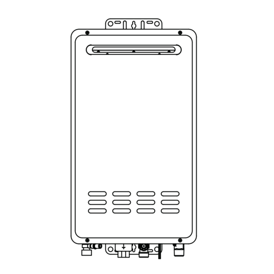
EXTERNAL DIMENSIONS (PH2-20ROF, PH2-25ROF & PH2-28ROF Outdoor Models) 13 7/8” (350 mm) 12 15/16” (328 mm) 3 1/2” (90 mm) 7/16” (10.5 mm) 8 7/16” (215 mm) 3/8” (10 mm) Gas Connection 3/4” NPT (F) (W/Supplied Gas Shutoff Valve) Water Inlet Connection Hot Water Outlet 3/4”... - Page 101 EXTERNAL DIMENSIONS (PHH-25ROF & PHH-32ROF Outdoor Models) 18 1/2” (470 mm) 5 15/16” (152 mm) Exhaust Outlet Air Intake 5 1/2” (140 mm) Hot Water Outlet Gas Connection 3/4” NPT (F) Connection 3/4” NPT (M) (W/Supplied Gas Shutoff Valve) 2 1/4” (57 mm) For Power Cord Water Inlet Connection 3/4”...
-
Page 102: Schematic Construction
SCHEMATIC CONSTRUCTION (PH2-20ROF, PH2-25ROF & PH2-28ROF Outdoor Models) Name of Parts Name of Parts Name of Parts Gas Connection 11 Bypass Pipe 21 Film Type OHL Gas Control Valve Assy. 12 Heat Exchanger 22 PC Board Lower Burner Assy. 13 Heat Transfer Coil 23 Fan Assembly Flame Rod 14 Fin... - Page 103 SCHEMATIC CONSTRUCTION (PH2-20RDVS, PH2-25RDVS & PH2-28RDVS Direct Vent Models) Name of Parts Name of Parts Name of Parts Gas Connection 11 Bypass Pipe Film Type OHL Gas Control Valve Assy. 12 Heat Exchanger Heat Exchanger Thermistor Lower Burner Assy. 13 Heat Transfer Coil PC Board Flame Rod 14 Fin...
- Page 104 SCHEMATIC CONSTRUCTION (PHH-25ROF & PHH-32ROF Outdoor Models) Name of Parts Name of Parts Name of Parts Front Cover 11 Gas Control Valve Assy. Water Control Valve Assy. Back Cover 12 Fan Assembly Water Supply Pipe Heat Exchanger 13 Film Type OHL Bypass Pipe 14 Igniter Turbulence Coil...
- Page 105 SCHEMATIC CONSTRUCTION (PHH-25RDV & PHH-32RDV Direct Vent Models) Name of Parts Name of Parts Name of Parts Front Cover 11 Gas Control Valve Assy. 21 Water Control Valve Assy. Back Cover 12 Fan Assembly 22 Water Supply Pipe Heat Exchanger 13 Film Type OHL 23 Bypass Pipe 14 Igniter...
-
Page 106: Operational Principle
OPERATIONAL PRINCIPLE (PH2-20ROF, PH2-25ROF & PH2-28ROF Outdoor Models) Exhaust Gas Gas Inlet Hot Water Outlet Water Inlet Name of Parts Name of Parts Name of Parts Hot Water Tap 11 Solenoid Valve 2 Film Type OHL Water Flow Servo 12 Solenoid Valve 3 Water Flow Sensor 13 Solenoid Valve 4 Fan Motor... - Page 107 OPERATIONAL PRINCIPLE (PH2-20RDVS, PH2-25RDVS & PH2-28RDVS Direct Vent Models) Exhaust Outlet Air Intake Gas Inlet Hot Water Outlet Water Inlet Name of Parts Name of Parts Name of Parts Hot Water Tap 11 Solenoid Valve 2 Film Type OHL Water Flow Servo 12 Solenoid Valve 3 Water Flow Sensor 13 Solenoid Valve 4...
- Page 108 OPERATIONAL PRINCIPLE WHEN SUPPLYING HOT WATER 1) By opening the Hot Water Top (1), the water fl ows through the Water Flow Sensor (3) to the Heat Heat Exchanger (20). 2) The frequency signal is given from the Water Flow Sensor (3) and when the PC Board (7) senses the signal that reached a certain frequency, the Fan (22) starts to turn round.
- Page 109 OPERATIONAL PRINCIPLE (PHH-25ROF & PHH-32ROF Outdoor Models) Name of Parts Name of Parts Name of Parts Hot Water Tap 11 Solenoid Valve 2 Film Type OHL Water Flow Servo 12 Solenoid Valve 3 Water Flow Sensor 13 Solenoid Valve 4 Fan Motor Water Inlet Thermistor Proportional Gas Control Valve...
- Page 110 OPERATIONAL PRINCIPLE (PHH-25RDV & PHH-32RDV Direct Vent Models) Name of Parts Name of Parts Name of Parts Hot Water Tap 11 Solenoid Valve 2 Film Type OHL Water Flow Servo 12 Solenoid Valve 3 Water Flow Sensor 13 Solenoid Valve 4 Fan Motor Water Inlet Thermistor Proportional Gas Control Valve...
- Page 111 OPERATIONAL PRINCIPLE WHEN SUPPLYING HOT WATER 1) By opening the Hot Water Top (1), the water fl ows through the Water Flow Sensor (3) to the Primary Heat Exchanger (20). 2) The frequency signal is given from the Water Flow Sensor (3) and when the PC Board (7) senses the signal that reached a certain frequency, the Fan (22) starts to turn round.
-
Page 112: Capacity
Capacity Hot Water Capacity Curve: PH2-20R Residential Use Inlet Water Temperature : 40°F (PH2-20R) Inlet Water Temperature : 50°F (PH2-20R) 0.40 0.40 When maximum temperature is set at 140°F When maximum temperature is set at 140°F When maximum temperature is set at 120°F When maximum temperature is set at 120°F 10.0 11.0... - Page 113 Capacity Hot Water Capacity Curve: PH2-25R Residential Use Inlet Water Temperature : 40°F (PH2-25R) Inlet Water Temperature : 50°F (PH2-25R) 0.40 0.40 When maximum temperature is set at 140°F When maximum temperature is set at 140°F When maximum temperature is set at 120°F When maximum temperature is set at 120°F 10.0 11.0...
- Page 114 Capacity Hot Water Capacity Curve: PH2-25R Commercial Setting Inlet Water Temperature : 40°F (PH2-25R Commercial Setting) Inlet Water Temperature : 50°F (PH2-25R Commercial Setting) 0.40 0.40 When maximum temperature is set at 185°F When maximum temperature is set at 185°F When maximum temperature is set at 120°F When maximum temperature is set at 120°F 10.0...
- Page 115 Capacity Hot Water Capacity Curve: PH2-28R Residential Use Inlet Water Temperature : 40°F (PH2-28R) Inlet Water Temperature : 50°F (PH2-28R) 0.40 0.40 When maximum temperature is set at 140°F When maximum temperature is set at 140°F When maximum temperature is set at 120°F When maximum temperature is set at 120°F 10.0 11.0...
- Page 116 Capacity Hot Water Capacity Curve: PH2-28R Commercial Setting Inlet Water Temperature : 40°F (PH2-28R Commercial Setting) Inlet Water Temperature : 50°F (PH2-28R Commercial Setting) 0.40 0.40 When maximum temperature is set at 185°F When maximum temperature is set at 185°F When maximum temperature is set at 120°F When maximum temperature is set at 120°F 10.0...
- Page 117 Capacity Hot Water Capacity Curve: PHH-25R Residential Use Inlet Water Temperature : 40°F (PHH-25R) Inlet Water Temperature : 50°F (PHH-25R) 0.40 0.40 When maximum temperature is set at 140°F When maximum temperature is set at 140°F When maximum temperature is set at 120°F When maximum temperature is set at 120°F 10.0 11.0...
- Page 118 Capacity Hot Water Capacity Curve: PHH-25R Commercial Setting Inlet Water Temperature : 40°F (PHH-25R Commercial Setting) Inlet Water Temperature : 50°F (PHH-25R Commercial Setting) 0.40 0.40 When maximum temperature is set at 185°F When maximum temperature is set at 185°F When maximum temperature is set at 120°F When maximum temperature is set at 120°F 10.0...
- Page 119 Capacity Hot Water Capacity Curve: PHH-32R Residential Use Inlet Water Temperature : 40°F (PHH-32R) Inlet Water Temperature : 50°F (PHH-32R) 0.40 0.40 When maximum temperature is set at 140°F When maximum temperature is set at 140°F When maximum temperature is set at 120°F When maximum temperature is set at 120°F 10.0 11.0...
- Page 120 Capacity Hot Water Capacity Curve: PHH-32R Commercial Setting Inlet Water Temperature : 50°F (PHH-32R Commercial Setting) Inlet Water Temperature : 40°F (PHH-32R Commercial Setting) 0.40 0.40 When maximum temperature is set at 185°F When maximum temperature is set at 185°F When maximum temperature is set at 120°F When maximum temperature is set at 120°F 10.0...
- Page 121 Wiring Diagram for PH2-20R, PH2-25R & PH2-28R - 121-...
-
Page 122: Wiring Diagram
Wiring Diagram for PHH-25 & PHH-32 - 122 -... -
Page 123: Thermistor Resistance Chart
Thermistor Resistance Chart Temp Resis- Temp Resis- Temp Resis- Temp Resis- ºF tance ºF tance ºF tance ºF tance K Ohm K Ohm K Ohm K Ohm 23.73 8.494 3.485 1.598 33.8 22.706 78.8 8.177 123.8 3.371 168.8 1.552 35.6 21.733 80.6 7.873... -
Page 124: Adjustment
Adjustment Adjustment of Burner Control Assembly (PC Board) PCB Replacement Procedure The content on this page is intended for use by qualifi ed service personnel only. WARNING: You will need to perform this procedure when you replace the PCB. Without this adjustment, the water heater may not function properly. WARNING: Improper adjustment, alteration, service or maintenance can cause property damage, personal injury, or death. - Page 125 8. Carefully remove the existing program chip, Figure 2 see fi gure 1 for location. Lightly grip the edges of the chip, top and bottom, as in fi gure 2, and pull the chip straight out from the PCB and set it aside.
- Page 126 Adjusting of Burner Manifold setting on the new PCB if the old PCB was completely broken or you could not get the value number [01 - 39]. Note: During the adjustment procedure if [EE] is displayed on the LED of remote control, adjust again with caution.
- Page 127 13. Adjustment of maximum manifold setting a. Open the hot water tap fully and make the maximum fl ow. b. Press and hold down the Adjusting Button (SW3). c. While holding the Adjusting Button (SW3); momentarily push the Maximum Button (SW2) on the PCB. (Note: It becomes to the maximum setting forcibly when the water is fl...
- Page 128 Standard Pressure (inch in w.c.) PHH-32RDV PHH-25RDV L.P. L.P. Minimum Capacity 0.91/11.0 0.71/7.1 0.91/11.0 0.71/7.1 Maximum Capacity 3.64/11.0 3.13/7.1 2.24/11.0 1.97/7.1 Slow Ignition Point 2.76/11.0 2.52/7.1 2.76/11.0 2.52/7.1 PHH-32ROF PHH-25ROF L.P. L.P. Minimum Capacity 0.89/11.0 0.65/7.1 0.89/11.0 0.65/7.1 Maximum Capacity 3.46/11.0 3.11/7.1 2.17/11.0 1.97/7.1 Slow Ignition Point...
- Page 129 High Altitude DIP Switch Adjustment For High Altitude Installation Above 3,280 Feet (1,000 M): WARNING: Improper adjustment, alternation, service or maintenance can cause property damage, personal injury, or death. When the water heater is installed above 3,280 feet (1,000m) or when the Burner Control Assembly (PCB) was replaced, the adjustment of DIP switch is required for high altitude installation.
- Page 130 Instruction for changing the setting to 85ºF (29ºC): WARNING: Improper adjustment, alternation, service or maintenance can cause property damage, personal injury, or death. Minimum Temperature Adjustment by the Remote Control (UMC-117) Required adjustment for 85ºF (29ºC) water temperature setting. WARNING: Changing this setting is done at your risk. WARNING: Water Temperature over 125ºF (52ºC) can cause severe burns instantly or death from scalds.
- Page 131 Instruction for changing the setting back to 120ºF (49ºC): WARNING: Improper adjustment, alternation, service or maintenance can cause property damage, personal injury, or death. Adjustment to LIMIT maximum water temperature setting to 120ºF (49ºC) by the Main Remote Control (UMC-117) WARNING: Changing this setting is done at your risk.
- Page 132 Instruction for changing the setting to 140ºF (60ºC) or 185ºF (85ºC): WARNING: Improper adjustment, alternation, service or maintenance can cause property damage, personal injury, or death. Maximum Temperature Adjustment by the Main Remote Control (UMC-117) Required adjustment for up to 140ºF (60ºC) water temperature setting for Residential product or 185ºF (85ºC) water temperature setting for Commercial version.
-
Page 133: Installation Instructions
Tankless Water Heater DUOnex™ 2-Unit System Installation Instructions It is very important that all persons who are expected to install, operate or adjust this DUOnex™ system and/or water heater read these instructions This kit contains: along with those instructions provided with the tankless water heater. 1 - DUOnex™... -
Page 134: Duonex Cable
3. While the LED on the Control Board and the “dash” on Typical Two Unit Manifold - Figure 2 the Remote Control Thermostat are blinking, push and Review the Use and Care Manual provided with the water hold the “SW2” button (see Figure 3) for three seconds. heater for complete information and installation instructions. - Page 135 Type 2 DUOnex Installation 1. Make sure power is disconnected and turn off gas and 7. Plug the cable into the connector marked “F” on the right water to both water heaters, then remove the front cover of the Control Board (see Figure 5). The connector will from each water heater.
- Page 136 140°F (60°C) Maximum Temperature Adjustment 120°F (49°C) Maximum Temperature Reset The factory default temperature setting is 120°F (49°C). Follow these instructions to set the system to allow up to 140°F (60°C) Follow these instructions to reset the water heater back to the operation.
- Page 137 MIC-185 Manifold Controller Operation and Installation Manual Table of Contents Safety Information Operation Instructions Trouble Shooting and Diagnosis Instructions for the Installer Extended Communications Board High Temperature Operation SAFETY PRECAUTIONS ● Read these instructions and the water heater instruction manual entirely before installing or operating the manifold controller and the water heater.
-
Page 138: Important Safety Information
IMPORTANT SAFETY INFORMATION READ ALL INSTRUCTIONS BEFORE USING. This system is designed to operate up to 20 tankless water heaters in a parallel manifold system. All tankless water heaters on a single system and connected to this controller must be a like model. Do not connect water heaters of different sizes, capacities, or types, to this system. - Page 139 Manifold Control System Components The MIC-185 Manifold Control System Contains the following: Weather Resistant Case, (1) Control Board, (1) 10ft Power Cord, (1) Hard Wire Pigtail , Mounting Hardware, and this Instruction. Weather Resistant Cabinet Upper Mounting Bracket (optional Kit) Manifold Cable Support MICS-180 Expansion Card Mounting Holes...
- Page 140 Typical Manifold System Section 1.0 - System Description A manifold system consists of the manifold controller referenced by main and independently feed a hot water main. See Figure 1.0. This this instruction, and a bank or 3 to 20 tankless water heaters. The system will not operate if the tankless water heaters are installed tankless heaters are installed in a parallel manifold system where in series, one feeding another.
- Page 141 Manifold System Operation Section 1.2 - Adjusting the Temperature Section 1.3 - Status Lights To adjust the system temperature higher, stop any hot water fl ow, The status lights on the remote consist of a “Burner On” indicator, and press the Up Button until you reach the desired temperature see Figure 1.3, and a Priority light.
- Page 142 Manifold System Operation / Installation Section 3.0 - Location Section 1.5 - Maximum Temperature Adjustment The factory default temperature setting is 120°F. Follow these in- The MIC-185 Manifold Control System can be installed indoors structions to set the system to allow Higher Temperature operation. or outdoors.
- Page 143 Manifold System Installation Section 3.3 - Manifold Control Cable Installation Section 3.2 - Electrical Connection The manifold controller communicates with each tankless water The manifold controller requires 120VAC/60Hz. Have a receptacle heater in the system through a communication cable. Each end of with the ground terminal near the manifold controller.
- Page 144 Manifold System Installation Secure the cable in the cabinet with one of the wire straps and Figure 3.3.a - Control Cable Installation at Water Heater screws as illustrated in fi gure 3.3.b. Excess cable may be bundled Control Board Layout for fi rst and second generation models inside the controller cabinet.
- Page 145 Manifold System Installation Connect the other end of the wiring harness with the two large molex Hang the remote on the wall plate and secure the bottom of the connectors to the respective sockets at the top of the main manifold remote with the supplied screw.
- Page 146 Manifold System Installation Section 4 - System Start Up Once the tankless water heaters have been setup and remote con- An LED indicator will light up “solid” next to each connector where a trol has been installed as instructed in Section 3, you may begin the control cable is plugged in to the main control board and/or expan- sion card.
-
Page 147: Safety Precautions
MIC-6 Manifold Controller Operation and Installation Manual Table of Contents This system is designed to operate up to 6 tankless water heaters in a parallel manifold system. All tankless water heaters on a single system and connected to this Safety Information controller must be a like model. - Page 148 IMPORTANT SAFETY INFORMATION READ ALL INSTRUCTIONS BEFORE USING. This system is designed to operate up to 6 tankless water heaters in a parallel manifold system. All tankless water heaters on a single system and connected to this controller must be a like model. Do not connect water heaters of different sizes, capacities, or types, to this system.
- Page 149 Manifold Control System Components The MIC-6 Manifold Control System Contains the following: MIC-6 Controller Card, (1) 1-feet MIC-Q-1 Type Q Master Control Cable, (1) 10” Ground Wire, Installation Hardware, and this Instruction. Available Accessories Tankless Water Heater Cabinet MIC-Q-1 - 1ft Manifold Control Cable MIC-Q-6 - 6ft Manifold Control Cable MIC-Q18 - 18ft Manifold Control Cable Water Heater...
- Page 150 Typical Manifold System Section 1.0 - System Description A manifold system consists of the manifold controller referenced by main and each feeds a hot water main. See Figure 1.0. This system this instruction, and a bank or 3 to 6 tankless water heaters. The will not operate if the tankless water heaters are installed in series, tankless heaters are installed in a parallel manifold system where one feeding another.
- Page 151 Manifold System Operation Section 1.2 - Adjusting the Temperature Section 1.3 - Status Lights To adjust the system temperature higher, stop any hot water fl ow, The status lights on the remote consist of a “Burner On” indicator, and press the Up Button until you reach the desired temperature see Figure 1.3, and a Priority light.
- Page 152 Manifold System Operation / Installation Section 1.5 - Maximum Temperature Adjustment Section 3.0 - Location The factory default temperature setting is 120°F. Follow these in- The MIC-6 Manifold Control System is designed specifi cally to structions to set the system to allow Higher Temperature operation. mount inside a tankless water heater.
- Page 153 Manifold System Installation Section 3.2 - Manifold Control Cable Installation Remove the front cover from the tankless water heater; there are 4 (four) screws holding the front cover on to the unit. The manifold controller communicated with each tankless water heater in the system through a communication cable.
- Page 154 Manifold System Installation Section 3.2.b - Control Cable Installation at the controller Section 4 - System Start Up Once the tankless water heaters have been setup and remote con- Disconnect the power from all tankless water heaters. Leave the trol has been installed as instructed in Section 3, you may begin the power disconnected until all the tankless water heaters in the sys- startup process.
- Page 155 Tankless Water Heater Commercial Conversion Installation Instructions This kit contains: NOTICE: Tankless water heaters Commercial Conversion Program Chip installed in a commercial application are Conversion Notifi cation Label not Energy Star qualifi ed. Remove the Commercial Warranty Energy Star label from the front of the Instructions for Chip Installation.
- Page 156 Chip Installation and Initiation Chip Installation 1. Make sure electrical power is disconnected and turn off the Control Board and set it aside. gas and water to the water heater, then remove the front 3. Remove the replacement chip from the packaging. cover from the water heater.
-
Page 157: Commercial Conversion
10. Press the UP arrow temperature adjustment button DANGER: Hotter water increases the potential for Hot several times to increase the temperature to a maximum Water SCALDS. of 185*, see Figure 4. This will verify the unit has been With this Commercial Conversion the temperature ranges successfully converted. - Page 158 Schematic Disassembly (PH2-20RDVS, PH2-25RDVS & PH2-28RDVS) - 158 -...
- Page 159 Schematic Disassembly (PH2-20RDVS, PH2-25RDVS & PH2-28RDVS) - 159 -...
- Page 160 Schematic Disassembly (PH2-20RDVS, PH2-25RDVS & PH2-28RDVS) - 160 -...
- Page 161 Parts List for PH2-20,25,28RDVS Name of Parts Name of Parts Name of Parts Front Cover Assembly Quick Fastener 751** Program Chip Water Control Assy. Upper Block Plate Drain Valve A 120V Cord Assembly Bypass Assembly Wiring Assembly F Label Packing Heat Exchanger Kit Quick Fastener Relay Cord Assembly...
- Page 162 Schematic Disassembly (PH2-20ROF, PH2-25ROF & PH2-28ROF) - 162 -...
- Page 163 Schematic Disassembly (PH2-20ROF, PH2-25ROF & PH2-28ROF) - 163 -...
- Page 164 Schematic Disassembly (PH2-20ROF, PH2-25ROF & PH2-28ROF) - 164 -...
- Page 165 Parts List for PH2-20,25,28ROF Name of Parts Name of Parts Name of Parts Front Cover Assembly Quick Fastener 751** Program Chip Water Control Assy. Power Cord Connector Assy. Exhaust Top Assy. Drain Valve A 120V Cord Assembly Bypass Assembly Wiring Assembly F Label Packing Heat Exchanger Kit Top Adapter Assembly...
- Page 166 Schematic Disassembly (PHH-32RDV & PHH-25RDV) - 166 -...
- Page 167 Schematic Disassembly (PHH-32RDV & PHH-25RDV) - 167 -...
- Page 168 Parts List for PHH-25, 32RDV Name of Parts Name of Parts Name of Parts Front Cover Assembly Quick Fastener 751** Program Chip Water Control Assy. Back Cover Support Plate Drain Valve A 120V Cord Assembly Front Cover Support Plate Bypass Assembly Wiring Assembly Heat Exchanger Kit Quick Fastener...
- Page 169 Schematic Disassembly (PHH-32ROF & PHH-25ROF) - 169 -...
- Page 170 matic Disassembly (PHH-32ROF & PHH-25ROF) - 170 -...
- Page 171 Parts List for PHH-25, 32ROF Name of Parts Name of Parts Name of Parts Front Cover Assembly Quick Fastener 751** Program Chip Water Control Assy. Back Cover Support Plate Drain Valve A 120V Cord Assembly Bypass Assembly Wiring Assembly F Label packing Heat Exchanger Kit Quick Fastener Terminal Assembly...
- Page 172 Paloma Industries, Inc. 2151 Eastman Avenue Oxnard, CA 93030 Phone: (805) 278-5499 Fax: (805) 278-5468 Tech Support Center: (800) 432-8373 Printed in USA 2011-08...
Need help?
Do you have a question about the PH2-20R OFN and is the answer not in the manual?
Questions and answers