Table of Contents
Advertisement
Quick Links
221723B.10.00
Installation & Servicing Instructions
T o b e l e f t w i t h t h e u s e r
INSET BBU 50
G.C. No. 44 047 02
For Use Only With Specially Designed Fire Fronts
This is a Cat I
Appliance
2H
Hepworth Heating Ltd.,
Customer Services:
Nottingham Road, Belper, Derbyshire. DE56 1JT
Tel: (01773) 828100
General/Sales enquiries:
One Contact Local Service
Tel: (01773) 824141 Fax: (01773) 820569
Fax: (01773) 828070
Advertisement
Table of Contents

Related Manuals for Glow-worm INSET BBU 50


Summary of Contents for Glow-worm INSET BBU 50
- Page 1 221723B.10.00 Installation & Servicing Instructions T o b e l e f t w i t h t h e u s e r INSET BBU 50 G.C. No. 44 047 02 For Use Only With Specially Designed Fire Fronts...
-
Page 2: Important Information
Important Information B.S.I Certification It is important that no alteration is made to the boiler without permission, in writing, from Hepworth Heating Ltd. Any alteration that is not approved by Hepworth Heating Ltd., could invalidate the B.S.I. Certification, the boiler warranty and could also infringe the current issue of the Statutory Requirements, see Section 1.1. - Page 3 Detailed recommendations are contained in the current issue of installation. the following British Standard codes of practice, The Glow-worm Inset 50 Back Boiler Unit, GC No. 44 047 02 is BS1251, BS5440 Part 1 and 2, BS5449, BS5546, BS5871, for use only with the Glow-worm Inset Fire Fronts.
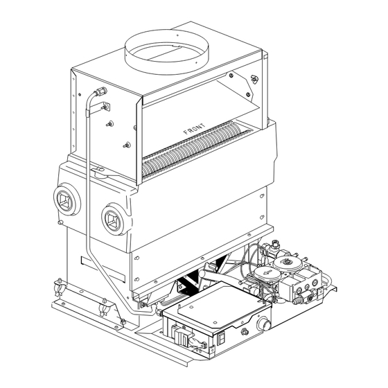
- Page 4 GAS CONNECTION RC ( in BSPT) FRONT ELEVATION SIDE ELEVATION DIMENSION 50 / BBU OVERALL DIMENSIONS (RIGHT HAND WATER CONNECTION SHOWN) Diagram 1.1 TABLE 1 INSET BBU 50 RANGE RATING 350mm 405mm MIN 500mm MAX PREPARED BASE Diagram 1.2 221723B...
- Page 5 1 General 1.5 Contents of Packaging Minimum flat area and fixture or surround protection clearance The boiler is delivered in one pack which contains all the parts required for installation. 1.6 Site Requirements For all types of installation a standard 16inch builder’s opening is required, see diagram 1.2.
-
Page 6: Types Of Installation
2 Types of Installation 2.1 Hearth PREPARED In ALL cases there MUST be a non-combustible hearth under the fire front. BOILER BASE For minimum dimensions of a hearth see diagram 2.1. Carpet or similar floor covering must not be placed on the hearth. - Page 7 3 Flue and Ventilation If a specially built compartment is constructed for the back 3.1 General boiler, it must conform to the requirements of the current issue The general recommendations of the current issue of BS5440 of BS5440 Part 1 and BS5871. Part 1 should be followed.
- Page 8 3 Flue and Ventilation 3.4 Precast Flue The ventilation openings may be direct to the outside air or with an internal room or space (such as a hall) which itself has a The appliance is suitable for fitting to a properly constructed permanent air vent of the same effective area.
- Page 9 4 Installation If the heat exchanger connections are opposite hand to that 22mm COPPER PIPE required, turn in the same manner as described in Section 4.3 SUPPLIED WITH APPLIANCE paragraph 5. (Do not cut) UNEQUAL 4.5 Heat Shield Assembly TEE PIECE If the boiler electrical supply cable has to be routed down the left hand side of the combustion chamber you must fit the heat INJECTOR...
- Page 10 4 Installation FITTING THE SECTION A-A 22mm CENTRAL 22mm COPPER PIPE INJECTOR HEATING RETURN SUPPLIED WITH APPLIANCE (Do not cut) INJECTOR (Supplied) 22mm BRAZED JOINT RETURN PIPE ASSEMBLY 28mm 28mm DOMESTIC FIXED HOT WATER DIMENSION FLOW UNEQUAL TEE 22mm COPPER (supplied) PIPE SUPPLIED 22mm...
- Page 11 4 Installation Reposition the back boiler unit into the builder’s opening. BAFFLES (centre in flueway) Connect the system pipework to the back boiler unit/pre- plumbed pipework. Connect gas supply to gas service cock. Leave gas service cock and gas fire front cock in the “OFF” position, see diagram 4.11 and 6.2.
- Page 12 4 Installation REAR Fully fit No. 8 3 / 8 in. DRAUGHT SENSING No. 8 3 / 8 in. DIVERTER screw into rear of TUBE socket. Centralise SECURING SCREWS flexible flue liner SCREW using the two No. 8 1 / 2 in. SOCKET screws provided.
-
Page 13: Electrical Wiring
5 Electrical Wiring 5.1 General Froststat Pipestat WARNING. This boiler must be earthed. Double ISOLATE THE ELECTRICAL SUPPLY BEFORE DOING ANY Pole Programmer Roomstat WIRING Switchspur All of the electrical installation must be correctly earthed and be in accordance with the current issue of BS7671 and be carried Pump 3 Way out by a competent person. - Page 14 5 Electrical Wiring 5.2 Thermostat Phial CONTROL THERMOSTAT Unwind the capillary avoid kinking. Route the capillary well clear OVERHEAT of any part of the back boiler which becomes hot. Use the PHIAL CUT-OFF capillary clips, supplied. Secure the capillary and push the phial DEVICE into the pocket, see diagram 5.4.
- Page 15 5 Electrical Wiring FLUE BLOCKAGE SAFETY DEVICE br - brown VALVE bk - black b - blue or - orange y - yellow g/y - green/yellow p - purple wh - white - red SWITCHED CONTROLLED SUPPLY 230V~50Hz TC-GND TC-SGN 3 PIN FUSE MAINS...
- Page 16 6 Commissioning 6.1 Commissioning the Back Boiler Turn gas service cock “C” to the “On” position making sure that the fire front service cock “D” is in the “Off” position, see diagram Before commissioning the back boiler, the whole of the system 6.2.
- Page 17 6 Commissioning Turn control thermostat knob “A” clockwise until “MAX” is 6.3 Clearance of Products against the pointer positioned on the control box front cover “F”. A clearance of products (spillage) test must be carried out after The main burner will light. installation of the back boiler and it's fire.
- Page 18 6 Commissioning 6.4 Commissioning the System Set all controls to operate the heating system. Adjust circulating pump and balance the system to give a temperature drop across the boiler of 11 C (20 F). At the appropriate flow rate, the resistance of the back boiler can be found by reference to diagram 6.4.
- Page 19 8 Servicing 8.3 Controls Assembly and Burner. FILTER SENSING TUBE Disconnect the union at the gas service cock, see diagram 8.2. FITTING Remove the thermostat phial and overheat cut-off device phial RETAINING NUT if fitted (sealed systems only), from the phial pockets, unclip the SECURING TUBING capillary tubes, see diagram 5.4.
- Page 20 8 Servicing 8.6 Main Burner - Injector Inspect the main burner injector for damage or blockage, clean or replace as necessary. If replacing ensure the new copper washer is fitted, see diagram 8.5. COPPER Do not use a wire or sharp instrument to clean the injector hole. WASHER EXTENDED MANIFOLD...
- Page 21 8 Servicing 8.7 Flue Blockage Safety Device Assembly DRAUGHT SECURING Gain access as relevant part of Section 8.3. Remove any dust DIVERTER SCREWS (4) and lint, inspect the pilot for damage. Remove the sensing tube adapter, to clean, blow through, do not use a wire or sharp instrument.
-
Page 22: Fault Finding
9 Fault Finding 9.1 Electrical Carry out the preliminary electrical system checks as contained On completion of the fault finding task which has required the in a multimeter instruction book. breaking and remaking of electrical connections, the checks for earth continuity, short circuit, polarity and resistance to earth Refer to electrical fault finding chart, diagram 9.1 and functional must be repeated. - Page 23 9 Fault Finding 9.4 Flue Blockage Safety Device and Ignition 9.2 Thermocouple Fault Finding To test the thermocouple, a meter with a range of 0 - 30mV is required together with a thermocouple interrupter To check the safety device and ignition, refer to fault finding test unit.
-
Page 24: Replacement Of Parts
10 Replacement of Parts Notes. 10.3 Electrode a) Replacement of parts must be carried out by a Proceed as in Section 10.2. competent person. b) Unless stated otherwise all parts are replaced in the 10.4 Ignition Lead reverse order to that of removal. Remove the control box lid. - Page 25 10 Replacement of Parts 10.6 Gas Valve Refer to the relevant parts of Section 8.3 to remove the controls ELECTRICAL assembly. PLUG Refer to diagram 10.2. Disconnect electrical plug. Disconnect the thermocouple nut at the gas valve and ease out. Disconnect interrupter electrical connections.
- Page 26 10 Replacement of Parts Take care to make sure that the hook at the back of the lid hooks CAPILLARY onto the control box before fitting the securing screw. SPLIT OVER HEAT The capillary tube must not touch any part of the back boiler that GROMMET CUTOFF DEVICE becomes hot, re-clip the capillary tube and push the phial into...
- Page 27 10 Replacement of Parts 10.13 Interrupter THERMOCOUPLE NUT Refer to diagram 10.10. ELECTRICAL Carefully disconnect the thermocouple nut. INTERRUPTER CONNECTIONS Remove the electrical connections. Remove the interrupter. 10.14 Insulation Follow the relevant instructions in Section 8.3 to remove the controls assembly and burner. Remove the three burner securing screws to remove the combustion chamber front cover from the controls assembly and burner, see diagram 8.2.
-
Page 28: Spare Parts
When spare parts are required apply to your local supplier. Please quote the name of the appliance, Glow-worm Inset BBU 50, with a Dovedale or Chatsworth BBU Fire Front, also the serial number of the boiler, to be found on the data label on the appliance.
Need help?
Do you have a question about the INSET BBU 50 and is the answer not in the manual?
Questions and answers