
Related Manuals for C-Nav 2050M


Summary of Contents for C-Nav 2050M
-
Page 1: User Guide
C-Nav2050 User Guide C-Nav World DGPS ® 730 East Kaliste Saloom Rd. Lafayette, La. 70508 USA Tel: +1 337 210 0000 Fax: +1 337 261 0192 E-mail: cnav.support@cnavgps.com... - Page 2 Contact the C-Nav® office or dealer nearest you: C-Nav Regional Office and Regional Distributor Contacts: North America: Lafayette (Head Office): +1 337 210 0000 Houston: +1 713 468 1536 South America: Rio de Janeiro: +55 21 2172 4000 Africa: South Africa:...
-
Page 3: Quick Start Guide
C-Nav2050 User Guide Quick Start Guide Hardware Connect 1. Connect the supplied LEMO 7-pin connector of the serial cable to COM2 of the C-Nav2050. Connect the DB9S end to the PC (or other controller device). 2. Connect the supplied LEMO 7-pin connector of the dual data cable to COM1 of the C-Nav2050. - Page 4 GPS antenna. Connect the other end to the TNC connector, labeled GPS ANT on the receiver. 5. C-Nav2050R Only: To track C-Nav Correction Service signals at high latitudes, mount the L- band antenna to a mast as described in Chapter 3.
-
Page 5: Software Setup
C-Nav2050 User Guide Software Setup C-Monitor/C-Setup After installation, double-click on the C-Monitor or C- Setup icon. Use the menu to select: File Open Port Choose communication settings: 19200 baud, parity none, 8 data bits, 1 stop bit Press “Ok” This software will allow you to view the positioning data in real-time and control the C-Nav2050. - Page 6 C-Nav2050 User Guide C-Nav2050G/M Front Panel C-Nav2050R* Front Panel *Notice additional TNC connector for L-band antenna...
-
Page 7: How To Enter A C-Nav Service Activation Code
C-Nav2050 User Guide How to Enter a C-Nav Service Activation Code C-Setup or C-Monitor While communicating with the receiver via the Control port (default COM2), select Device License Auth & Cancel. Select Browse then navigate to and select the attached license file, obtained from C-Nav Support. -
Page 8: Subscription Activation Notes
C-Nav2050 User Guide Subscription Activation Notes Entering a new authorization code when the unit already has an active authorization will cancel the current authorization. This may not be a problem if the new code overlaps the old code, however, if your new subscription does not start for some time after the old subscription, you should not enter the new code until the old subscription has expired. -
Page 9: How To Deactivate The C-Nav Service
Send the generated cancel code to C-Nav Support for cancellation verification. Alternate Method If you do not have the latest C-Nav software, you can deactivate service by doing the following: C-Setup or C-Monitor While communicating with the receiver via the... -
Page 10: C-Navigator
Code found in the attached file then select Apply. An 8-digit Cancel Verify Code will appear if the cancellation code was entered correctly. Return the Cancel Verify Code to C-Nav Support to stop signal charges. Subscription Deactivation Notes: With the latest C-Nav software versions, entering a cancel code will stop your subscription immediately. -
Page 11: Table Of Contents
Hardware Connect ................i Software Setup................. iii C-Monitor/C-Setup ................iii C-NaviGator ..................iii How to Enter a C-Nav Service Activation Code ........v C-Setup or C-Monitor ................v C-NaviGator ..................v Subscription Activation Notes ............vi How to Deactivate the C-Nav Service ..........vii C-Setup or C-Monitor .............. - Page 12 0183 Data ................1-6 Antennae .....................1-7 Standard ..................1-7 Airborne (option) ................1-8 L-band (option – C-Nav2050R only) ..........1-8 Controller.....................1-9 Unique Features..................1-9 C-Nav Correction Service ..............1-9 Positioning Flexibility..............1-9 RTK Extend™ ................1-10 Data Sampling ................1-10 GPS Performance................1-11 Rugged Design ................1-11 Accuracy ..................1-11 Chapter 2 Interfacing ..........2-1...
- Page 13 Standard Antenna Radiation Pattern ..........B-3 L-band Antenna Specifications ............. B-4 L-band Antenna Radiation Pattern..........B-6 Airborne Antenna Dimensions ............B-7 Appendix C C-Nav DGPS Correction Service ..... C-1 Description ..................C-1 Infrastructure .................C-2 Reliability..................C-3 How to Access the C-Nav Correction Service.......C-4 Appendix D NMEA Data Output Messages....
- Page 14 Certificate of Registration ..............E-1 Certificate of Type Approval ............... E-3 Ministry of Transportation of the Russian Federation Certificate of Type Approval ..................... E-6 Appendix F C-Nav L-band Correction Signal....F-1 Appendix G Glossary ............ G-1 Abbreviations..................G-1 Definitions...................G-5 Appendix H Index............H-1...
-
Page 15: List Of Figures
Figure 6: DC Power Cable Pin Assignments ........ 2-3 Figure 7: Isolation Mount Adaptors..........2-4 Figure 8: C-Nav 2050 Front View ..........2-5 Figure 9A: C-Nav Serial Cable Pin Assignment ......2-6 Figure 9B: C-Nav Serial Cable Pin Assignment ......2-7 Figure 10: C-Nav2050M Back View ..........2-9 Figure 11: Event Cable Wiring Diagram ........ - Page 16 C-Nav2050 User Guide List of Tables Table 1: Supplied Equipment ............1-3 Table 2: Serial Cable Pin-Outs............2-6 Table 3: Acceptable RS-232 Cable Lengths .........2-7 Table 4: Event Wiring Connections ..........2-10 Table 5: Link LED Indication (Default).........2-12 Table 6: Base Station Indication..........2-13 Table 7: GPS Light Indication............2-13 Table 8: Acceptable Coaxial Cable Lengths........3-11 Table 9: Dual Data Interface Cable I/O ........3-17...
-
Page 17: Notices
Translation in any language is prohibited without the expressed written consent of the copyright holders. Trademarks C-Nav is a registered product of C&C Technologies, ® Inc. (C-Nav GPS Division). All other products and brand names are trademarks or registered trademarks of their respective holders. -
Page 18: Fcc Notice
C-Nav2050 User Guide FCC Notice This device complies with Part 15 Subpart B Class B of the FCC Rules. Operation is subject to the following two conditions: 1. This device may not cause harmful interference, 2. This device must accept any interference received, including interference that may cause undesired operation. -
Page 19: C-Nav Correction Service Licensing
This limited warranty period is one (1) year from date of purchase. C-Nav Correction Service Licensing The C-Nav signal requires a subscription that must be purchased to gain access to the service. Licenses are non-transferable, and are subject to the terms of the C- Nav Correction Service License Agreement. -
Page 20: Usg Far
C-Nav2050 User Guide For further details on the C-Nav Correction Service Signal Network, subscriptions, deactivations, terms, conditions and its capabilities, refer to Appendix C of this manual or send an email inquiry to cnav.support@cnavgps.com USG FAR Technical Data Declaration (Jan 1997) The Contractor, C&C Technologies, Inc... -
Page 21: Cocom Limits
C-Nav2050 User Guide COCOM Limits The U.S. Department of Commerce requires that all exportable GPS products contain performance limitations so that they cannot be used in a manner that could threaten the security of the United States. The following limitations are implemented on the C-Nav2050 GPS Receiver. -
Page 22: Revision History
C-Nav2050 User Guide Revision History Rev A (Dec 2002) Initial release Inserted missing block bracket Rev B (Feb 2003) (open) in Table 2 Cell A2 Replaced Redondo Beach Rev C (Nov 2003) contact information with Torrance. Added appendix detailing specifications for Event input; wiring diagram, Event HI/LO wiring table, and message Rev D (Mar 2005) - Page 23 Add UltraRTK™ specs Add NMEA message GBS/GRS ITRF2000 update to ITRF2005 Rev G (Jul 2008) (Apr 08) as reference for C- Nav position outputs Update text and graphics pertaining to C-Nav Correction Service -- new satellite uplink sites Add Airborne Antenna Drawing...
-
Page 24: Use Of This Document
C-Nav2050 User Guide Use of this Document This User Guide is intended to be used by someone familiar with the concepts of GPS and satellite surveying equipment. Note indicates additional information to make better use of the product. This symbol means Reader Be Careful. Indicates a caution, care, and/or safety situation. -
Page 25: Related Documents
Describes the control and output data message formats utilized by this instrument (for customer programming purposes; contact cnav.support@cnavgps.com obtain a digital copy). C-Nav Online Resources Includes the latest software/firmware updates, users manuals, FAQs, Satellite Calculator and help files for all C-Nav products: www.cnavgps.com/support... -
Page 26: Related Standards
C-Nav2050 User Guide Related Standards ICD-GPS-200 NAVSTAR GPS Space Segment / Navigation User Interfaces Standard. ARINC Research Corporation; 2250 E. Imperial Highway; El Segundo, California 90245 RTCM-SC-104 Recommended Standards For Differential GNSS Service. Radio Technical Commission For Maritime Services; 1800 N. Kent St, Suite 1060; Arlington, Virginia 22209 CMR, CMR+ Compact Measurement Record;... -
Page 27: Publicly Operated Sbas Signals
C-Nav2050 User Guide Publicly Operated SBAS Signals RTCA/DO-229D The Radio Technical Commission for Aeronautics (RTCA) develops consensus-based recommendations regarding communications, navigation, surveillance, and air traffic management (CNS/ATM) system issues. RTCA. 1828 L Street, NW, Suite 805, Washington, DC 20036. These organizations implement the RTCA/DO-229D standard set by the RTCA: WAAS (Wide Area Augmentation System) -
Page 28: Contact Information
C-Nav2050 User Guide Contact Information If you have a problem and cannot find the information you need during the installation or operation of a C-Nav GPS product, contact: C-Nav Support Phone: +1 337 210 0000 (24/7 support) Fax: +1 337 261 0192 Phones are answered 24 hours, 7 days a week, with on-call technical support engineers available. - Page 29 C-Nav GPS Support to obtain a Return Material Authorization (RMA) number before returning any items or products. A fault or failure description will be required before C-Nav will issue an RMA number that must be used to identify and track all returned equipment. xxvii...
- Page 30 C-Nav2050 User Guide xxviii...
-
Page 31: Chapter 1 Introduction
GPS Receiver System The C-Nav2050 GPS receiver delivers unmatched accuracy to the precise positioning community. This unique receiver is designed to use the C-Nav Correction Service Network, which is a worldwide Satellite Based Augmentation System (SBAS) for decimeter-level position accuracy (post- convergence period). -
Page 32: Supplied Equipment
C-Nav2050 User Guide Supplied Equipment Figure 1: C-Nav2050 Supplied Equipment Figure 2: L-band Antenna (C-Nav2050R Only) -
Page 33: Table 1: Supplied Equipment
Antenna Mounting Poles, 1 ft (x2) (P/N: WES534610) Antenna Mounting Pole Adaptor 5/8” BSW 1”-14 UNS-2B (P/N: 3250005-0) (P/N: 4250005-10) is an optional 10ft (3m) unterminated power cable fitted with a LEMO plug type with red strain relief. Contact C-Nav Support for more information. -
Page 34: Models
C-Nav2050 User Guide Models C-Nav2050G This model is designed for: Geographic Information System Data Acquisition Aerial/LiDAR Surveying Hydrographic Surveying Post-processed Dual-frequency Surveys Real-time Positioning Applications The receiver is packaged for mobility and can be carried in a backpack with the antenna either pole-mounted from the backpack or on a survey pole. -
Page 35: C-Nav2050R
8250001-0) and C-Nav Corrections Service Signals (P/N: 825R003-0). The purpose of the separate antenna systems is to provide better low-elevation satellite detection to C-Nav Correction Service signals in high- latitude locations. The GPS antenna port provides 4.3VDC and the C-Nav antenna port provides 5.0VDC. -
Page 36: Nct Binary Proprietary Data
C-Nav2050 User Guide NCT Binary Proprietary Data The receiver can output proprietary raw data containing information including (but not limited to): Satellite Ephemeris (0x81) Satellite Almanac (0x44) Raw Pseudorange Measurements (0xB0) Position, Height, & Time (0xB1) Velocity & Heading (0xB1) Signal to Noise (0x86) Channel Status (0x86) Correction Data (mirror data;... -
Page 37: Antennae
C-Nav2050 User Guide Standard: ALM – GPS Almanac Data GBS – GNSS Satellite Fault Detection GGA – GPS Fix Data GLL – Geographic Position – Lat / Lon GRS – RAIM Monitoring Data GSA – GNSS DOP & Active Satellites GST –... -
Page 38: Airborne (Option)
(P/N: 8250002- 0) tracks all GPS, W AAS, EGNOS, MSAS, GAGAN and C-Nav Correction Service signals. Our compact GPS antenna has excellent tracking performan ce and a stable phase center for GPS L1 and L2. This antenna is listed in the NOAA GPS Antenna Calibration tables as NAVAN2008T. -
Page 39: Controller
This may be accomplished using a PC, Tablet PC or Personal Digital Assistant (PDA) and a software program which implements the rich control language defined for C-Nav GPS products. Refer to the users guide of the controller solution for further information. Refer to Chapter 4 for descriptions of C-Nav... -
Page 40: Rtk Extend
RTK Extend™ RTK Extend™ enables continuous real-RTK/RTK level positioning accuracy during radio communication outages by utilizing C-Nav’s global Correction Service network corrections. Traditionally, when an RTK rover loses communication with the base station, it is unable to continue to provide... -
Page 41: Gps Performance
The system provides instant <0.5cm position accuracy when UltraRTK™ correction signals are used (base- line, <40km, 0.5cm +1ppm). Contact C-Nav Support for UltraRTK™ information and subscriptions. UltraRTK™ requires firmware version 4.2 or higher. The system provides instant <1cm position accuracy when RTK correction signals are used. - Page 42 C-Nav2050 User Guide 1-12...
-
Page 43: Chapter 2 Interfacing
C-Nav2050 User Guide Chapter 2 Interfacing This chapter details the C-Nav2050 GPS receiver connectors, LED display, appropriate sources of electrical power, and how to interface the communication ports Electrical Power A front panel 4-pin LEMO female connector provides electrical power to the C-Nav2050. Pin assignments are given below in Figure 3;... -
Page 44: Figure 4: Universal Power Adapter
C-Nav2050 User Guide The C-Nav2050 is supplied with a universal AC/DC, 12V, 2A power adapter (P/N: 3250012-0). See Figure 4. See Figure 6 for power cable pin assignments. Figure 4: Universal Power Adapter Replacement AC power cords are available through small appliance retailers (Radio Shack, Walmart, Best Buy, etc.) Figure 5: AC Power Cord... -
Page 45: Figure 6: Dc Power Cable Pin Assignments
C-Nav2050 User Guide (P/N: 4250005-10) is an optional 10ft (3m) unterminated power cable fitted with a LEMO plug type with red strain relief. The wiring color code and pin assignments are labeled on the cable assembly and provided below. Figure 6: DC Power Cable Pin Assignments The GPS receiver is protected from reverse polarity with an inline diode It will operate on any DC voltage... -
Page 46: Isolation Mount Adaptor
Isolation Mount Adaptor The C-Nav2050 chassis/ground is internally connected to the power ground, thus the Isolation Mount Adaptor (P/N: PRE2025) may be needed when using vessel- supplied DC power. Contact C-Nav Support for available isolation solutions. Figure 7: Isolation Mount Adaptors... -
Page 47: Communication Ports
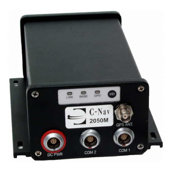
The C-Nav2050 is configured as a DCE device. Laptop and desktop computers are configured as DTE devices, therefore a straight-through cable provides proper connectivity (PC TXD pin 2 connects to C-Nav2050 RXD pin 2). Figure 8: C-Nav 2050 Front View... -
Page 48: Figure 9A: C-Nav Serial Cable Pin Assignment
CTS - Clear To Send 5VDC to Bluetooth Wireless Receiver RD - Receive Data TD - Transmit Data DTR - Data Terminal Ready RTN - Return [Ground] DSR - Data Set Ready RTS - Request To Send Figure 9A: C-Nav Serial Cable Pin Assignment... -
Page 49: Figure 9B: C-Nav Serial Cable Pin Assignment
C-Nav2050 User Guide Figure 9B: C-Nav Serial Cable Pin Assignment Connect pin 5 to shield of cable at both ends. Refer to Table 3 for acceptable RS-232 Cable Lengths. Table 3: Acceptable RS-232 Cable Lengths Maximum Data Rate (bps) Maximum Length 2,400 (2.4K) -
Page 50: Can Bus/Event (C-Nav2050M Only)
CAN Bus specifications are diverse. Drivers for the existing hardware must be tailored to the specific manufacturer’s equipment being interfaced. For further information, contact C-Nav Support. Event The C-Nav2050M accepts an event input pulse to synchronize external incidents requiring precise GPS time tagging, such as aerial photography. -
Page 51: Pps
Pulse delay, default 0mS, range 0 – 999mS Rising or Falling Edge Synchronization A BNC female connector provides the 1PPS output pulse. A 3ft (0.9m) long, BNC male to BNC male cable (P/N: 4250006-3) is available by contacting C-Nav Support. Figure 10: C-Nav2050M Back View... -
Page 52: Event Input Configuration
C-Nav2050 User Guide Event Input Configuration Figure 11 details the wiring of the Event/Can cable assembly (P/N: 4250007-3). Table 4 details the wiring configuration required for Event-Hi, and Event-Lo pulse sensing. Figure 11: Event Cable Wiring Diagram Table 4: Event Wiring Connections Pin # Signal Name Color... -
Page 53: Figure 12: 1Pps & Event Latch Configuration
C-Nav2050 User Guide The Event Input can be triggered on the Rising or Falling edge of the input pulse. Configuration is possible through the StarUtil program, available on the C-Nav website at www.cnavgps.com/support Figure 12 is a screen capture of the program’s 1PPS &... -
Page 54: Indicator Panel
Indicator Panel Figure 14: C-Nav2050 Indicator Panel The indicator panel provides a quick status view of the C-Nav Correction Service signal strength, base station correction type, GPS navigation/operating mode, and the On/Off (I/O) switch, respectively. Each set of indicators has three LEDs. The GPS LEDs blink at the PVT positioning rate (1, 5, 10, or 25Hz). -
Page 55: Base Leds
Base LEDs Table 6: Base Station Indication BASE Status The BASE LEDs are not utilized in C-Nav Correction Service operating mode The following LEDs reflect the type of RTK corrections when the C-Nav2050 is operated as a Base Station RTK/UltraRTK™... - Page 56 C-Nav2050 User Guide 2-14...
-
Page 57: Chapter 3 Installation
C-Nav2050 User Guide Chapter 3 Installation This chapter provides guidance on hardware installation for optimum performance Prior to commencing any installation, discuss proposed mounting locations/methods and cable routes with the vessel chief engineer or master to ensure that all parties are aware of the work to be done and the risks involved. -
Page 58: Antenna Location
C-Nav2050 User Guide Figure 15: Standard GPS/L-band Antenna Antenna Location When choosing an antenna location, consider the following: Locate the antenna as high on the mast as possible, where it has a clear view of the sky, to an elevation angle of 7º if possible. Obstructions below 15º... - Page 59 Use satellite prediction software with a recent satellite almanac to assess the impact on satellite visibility at your location. An L-band Communication Satellite Locator tool is available on C-Nav’s website to aid in determining potential obstructions to the C-Nav Correction...
-
Page 60: Antenna Mounting Pole
A clear line of sight between the antenna and the local INMARSAT satellite is required to track the C-Nav Correction Service signal. INMARSAT satellites are geo-synchronized 35,786kms above the Equator, currently at Longitudes: 142°... -
Page 61: Antenna Mounting Pole Adaptor
The antenna mounting pole adaptor converts: From: 5/8” BSW (depth of 14mm [0.55”]) To: 1”-14UNS-2B (depth of 32mm [1 ¼”]) C-Nav recommends that the supplied mounting adaptor hardware (P/N: 3250005-0) be used in conjunction with the supplied antenna mounting pole (P/N: WES534610) as the primary means of mounting. -
Page 62: Antenna Installation
C-Nav2050 User Guide Antenna Installation 1. Once the antenna location has been determined based on the previously mentioned criteria, mount the antenna onto an antenna mounting pipe This should be done on deck prior to climbing the mast as mounting the antenna aloft poses potential risks to personnel and equipment due to possible dropped object hazards. -
Page 63: L-Band Antenna (C-Nav2050R Only)
C-Nav2050 User Guide L-band Antenna (C-Nav2050R Only) The separate L-band antenna (P/N: 825R003-0) for the C-Nav2050R is used in high latitude applications and most frequently on marine vessels. This is an active antenna, meaning it has a built-in LNA Therefore, this antenna should have good isolation from other near- frequency antennae. -
Page 64: Coaxial Cable
C-Nav2050 User Guide Coaxial Cable Proper installation of coaxial cables is important to ensure successful communication between the antenna and the GPS rece iver. The system is supplied with 12ft (3.6m) of RG58/U cable (P/N 4250001-12). The cable is fitted with a right angle male TNC connec tor and a straight male TNC connector respectively. -
Page 65: Coaxial Cable Installation
(see Appendix B). In-line amplifiers may also over- saturate the receiver front-end if improperl used. Contact C-Nav Support for more information on available in-line amplifiers. Coaxia l Cable Installation... - Page 66 C-Nav2050 User Guide With the cable connected to the antenna, run t cable down the mast, securing with zip tie every 2 or 3 feet. 4. Carefully lay the cable along the chosen route to further detect any potential kinks, bends or spots where the cable may become damaged.
-
Page 67: Lightning Protection
Install protective devices in compliance with local regulatory codes and practices. Protective devices must pass DC power from the receiver to the antenna. Conta C-Nav Support for more information on av ailable lightning protection solutions. GPS R eceiver The C-Nav2050 GPS receiver is best installed using the integrated mounting brackets. -
Page 68: Gps Receiver Location
C-Nav2050 User Guide GPS Receiver Location When choosing a location for GPS Receiver installation, consider the following: Avoid placing the receiver in direct sunlight, places with inadequ ate ventilation, or where it might be subject to excessive dust. Ensure the rece iver is mounted securely to a flat surface in an area with little vibration. -
Page 69: Block Diagrams
C-Nav2050 User Guide 50mA max power the GPS antenna preamplifier The L-band connector (C-Nav2050R only) pr ovides: 5.0 VDC and, 50mA max power to the C-Nav Correction Service-only antenna preamplifier. not disconnect the antenna when the GPS unit is ered on. -
Page 70: Figure 21: Radio Port Configuration In Starutil
C-Nav2050 User Guide These user configurable physical ports are COM1, COM2, and Radio/Diagnostic. The COM ports are described in the next section. The Radio/Diagnostic port connects to an internal UHF radio and is not used, nor should it be assigned as a logical port in any of the C- Nav2050 products. -
Page 71: Communication Port Connectivity
DCE device. COM2 is the C-Nav2050 logical control port by default. COM1 can be configured as the control port by using the appropriate C-Nav controller software. However, there ar e caveats to Logical / Physical port... -
Page 72: Dual Data Interface Cable
C-Nav2050 User Guide Figure 23: Communication Port Connections Dual Data Interface Cable Use of the dual-data interface cable (P/N: 4250004-0) to COM1 via the LEMO 7-pin connector allows simultaneous input of external Radio/IALA correction data messages and position data messages to your controlling device. -
Page 73: Figure 25: Dual Data Cable Pin Assignment Diagram
C-Nav2050 User Guide Refer to Table 9 and Figure 25 for Dual Data Cable interface with C-Nav2050 (COM1, blue and red cable in Figure 26). Table 9: Dual Data Interface Cable I/O Figure 25: Dual Data Cable Pin Assignment Diagram 3-17... -
Page 74: Figure 26: Optional Com Port Setup With Dual Data Cable
C-Nav2050 User Guide External 3 Party connection i nput (RTCM Controller Solution (C-Monitor, C-Setup, Connect to Nav or StarUtil or DP System for C-NaviGator) NMEA Data Message Output Figure 26: Optional Com Port Setup with Dual Data Cable 3-18... -
Page 75: Chapter 4 Configuration
(potentially in conjunction with other devices or utilities). To facilitate this effort, C-Nav has two additional tools available: the Integrators Tool Kit (ITK) and the Technical Reference Manual (TRM). Information on these tools is available from the C-Nav web site and by contact C-Nav support. -
Page 76: Factory Default Settings
C-Nav2050 User Guide Factory Default Settings COM1 Factory Default Configuration - Data port Rate – 19.2Kbps Output of NMEA messages GGA & VTG set @ 1Hz* COM1 is the factory default data port and manages the non-NCT binary proprietary messages that are input and/or output to/from the receiver. -
Page 77: Com2
C-Nav2050 User Guide igure 28: StarUtil Rover Navigation Setup This po rt is typically used to output data to othe devices or machines that can make immediate use of the pre cise positi oning data available from the C- Nav2050. COM1 also serves as the DGPS correction inpu t/output port when NCT RTK/UltraRTK™, CMR, o RTCM... -
Page 78: Factory Default Output Messages
C-Nav2050 User Guide This port is normally used to input and output proprietary messages used for navigation and receiver setup. T able 10 describes the default messages needed to best initiate surveying with minimal effort. The user has full contr ol over the utilized messa types and their associated rates via the controller soft... - Page 79 C-Nav2050 User Guide 44 Packed Almanac: Data corresponding to each satellite in the GPS constellation, including: GPS Week number of collected almanac, GPS Time of week [in seconds] of collected almanac, almanac reference week, almanac reference time, almanac source, almanac health, pages 1-25, and sub-frames 4 and 5.
-
Page 80: Logging Raw/Binary Data Using Starutil
C-Nav2050 User Guide Logging Raw/Binary Data Using StarUtil C-Nav RAW GPS 'binary' data can easily be recorded using the StarUtil application on the PC that is connected to the control port of the C-Nav2050 unit. Logged data files can help C-Nav Support to better... -
Page 81: Figure 30: Nct Binary Message Output Configuration
C-Nav2050 User Guide 2. Ensure that the follo wing NCT 'binary' messages (minimum) are enabled for output from the Control Port (On Change): 0x44 - Almanac 0x81 - Ephemeris 0x86 - Channel Status 0xA0 - Alerts 0xB0 - Raw Measurements 0xB1 - Solution 0xB2 - Satellite Se lection... -
Page 82: Figure 31: Starutil Data Logging Utility
5. If desired, unwanted data files can be purged to save disk space. The RAW 'binary' data will be recorded in 24 hour data files that can be saved to a CD-ROM, or compressed using WinZip, and uploaded to the C-Nav FTP site for analysis. -
Page 83: Logging Raw/Binary Data Using C-Setup/C-Monitor
Raw GPS 'b inary' data files can be sent to C-Nav Support to help resolve GPS-related queries or cer s. Sending data files to C-Nav Support can be acco p m lished by e-mail attachment, upload to the C- Nav FT... - Page 84 These compressed files can then be attached to an e-mail to C-Nav Support (2MB max). For unavoidably large data files (2MB or more), another method is to use the C-Nav FTP site. This can be accomplished as follows: Access the C-Nav FTP site at ftp.cctechnol.com...
-
Page 85: Rtk Rover/Base Station Setup
C-Nav2050 User Guide RTK Rover/Base Station Setup For more information on the setup of the C-Nav2050 a rover, contact C-Nav Support Party Controller Configuration Se ttings ase refer to the third party controller solution nual/users guide if the C-Nav2050 GPS receiv er is t of an integrated solution. - Page 86 C-Nav2050 User Guide 4-12...
-
Page 87: Chapter 5 Safety Instructions
GPS equipment, the limitations thereof, and these safety instructions prior to use of this equipment. Transport lways carry C-Nav equipment in either the original acking material or packaging which provides protection to the receiver and antenna against shock and vibration. -
Page 88: Safety First
Other manufacturer’s equipment must be used in accordance with the safety instructions issued by that manufacturer. This includes other manufacturer’s equipment that may be attached to C-Nav manufactured equipment. Always use the equipment in accordance with local regulatory practices for safety and health at work. -
Page 89: Appendix A Gps Receiver Specifications
C-Nav2050 User Guide Appendix A GPS Receiver Specifications The technical specifications of this unit are detailed below. C-Nav is constantly improving, and updating our technology. For the latest technical specifications for all products go to: www.cnavgps.com These GPS receivers are fitted with an internal Lithium... -
Page 90: Time-To-First-Fix (Cold Start
C-Nav2050 User Guide Superior interference suppression Patented multipath rejection Output of NMEA 0183 v3.1 messages Self-survey mode (position averaging) CAN bus interface, 1PPS Output, Event Marker (C-Nav20 50M Only) Time-To-First-Fix (Cold Start) Satellite < 60 Seconds (typical; with Almanac) Acquisition <... -
Page 91: Measurement Performance
C-Nav2050 User Guide Measurement Performance C-Nav Correction Service Accuracy Position (H): <10 cm Position (V): <15 cm Velocity: 0.01 m/s Real-time RTCA/DO-229D Standard SBAS Accuracy (WAAS/EGNOS/MSAS/GAGAN) Position (H): <0.5 m Position (V): <0.7 m Velocity: 0.01 m/s Code Differential GPS <200km (RMS) Position (H): <12 cm +2ppm... -
Page 92: User Programmable Output Rates
C-Nav2050 User Guide User programmable output rates C-Nav2050G 1, 2, 5Hz Standard 10 & 25Hz Optional Raw data 1, 2, 5Hz Standard 10, 25, & 50Hz Optional C-Nav2050M 1, 2, 5, 10Hz Standard 25Hz Optional Raw data 1, 2, 5, 10, 25Hz Standard 50Hz Optional Data Latency <... -
Page 93: Connector Assignments
1 or 9 WAAS /EGNOS/M SAS/GAGAN NCT Pr oprietary RTK Correction C-Nav Correction Servi ce (RTG a (I/O) Dual) RTCM 18,19 or 20, 21 CMR+/CMR (Msg. 0, 1, 2) RTK data only ava ilab le in C-Nav receivers optioned for RTK eration. -
Page 94: Led Display Functions (Default
C-Nav2050 User Guide LED Display Functions (Default) C-Nav Correction Service Signal Link Strength (Default; U Programmable) N/A in Standard C-Nav2050 Base Station Configuration (User Programmable) Position Quality Satellite Based Augmentation System Signals WAAS/EGNOS/MSAS/GAGAN C-Nav Correction Service Physical and Environmental Size (L x W x H): <... -
Page 95: Figure A1: C-Nav2050 Front Dimensions
C-Nav2050 User Guide Figure A1: C -Nav2050 Front Dimen sions Figure A2: C-Nav2050 Base Plate Dimensions... - Page 96 C-Nav2050 User Guide...
-
Page 97: Appendix B Antenna Specifications
Appendix B Antenna Specifications Standard Antenna Specifications Part Standard Antenna Part Number 8250001-0* Frequency 1525-1585 MHz GPS L1 plus INMARSAT C-Nav Correction Service 1217-1237 MHz GPS L2 L1 Phase Centre 58.7mm Polarization Right Hand Circular (RHCP) Pre–Amplifier 39dB gain (+/-2dB) Noise Figure <2.5dB... -
Page 98: Figure B1: P/N: 8250001-0 Antenna Dimensions
C-Nav2050 User Guide Figure B1: P/N: 8250001-0 Antenna Dimensions To achieve the greatest level of accuracy, the absolute phase center values must be incorporated into your processing. Phase center information on this antenna is found on the antenna bottom, and in Figure B2. -
Page 99: Standard Antenna Radiation Pattern
C-Nav2050 User Guide Figure B2: C-Nav2 050 Antenna Phase Center Dime nsions Standard Antenn a Ra diation P attern 6.5dB @ 90º 32º 24º -4dB @ 5º -4.5dB @ 5º 07-00008-A Figure B3 : AN-2004T Radiation Pattern Optimal antenna p erform ance is realized at elevations... -
Page 100: L-Band Antenna Specifications
C-Nav2050 User Guide L-band Antenna Specifications Part L-band C-Nav2050R Antenna Part Number 825R003-0 Frequency 1525-1585 MHz INMARSAT C-Nav Correction Service Polarization Right Hand Circular (RHCP) Pre–Amplifier 25dB gain min. (to coax end) Noise Figure 1.0dB typical Impedance 50 Ohms Input Voltage 3.0 to 5.5 VDC... -
Page 101: Figure B4: C-Nav2050R Antenna Dimensions
C-Nav2050 User Guide Figure B4: C-Nav2050R Antenna Dimensions Figure B5: C-Nav2050R Antenna Mounts... -
Page 102: L-Band Antenna Radiation Pattern
C-Nav2050 User Guide L-band Antenna Radiation Pattern Figure B6: C-Nav2 05 0R Antenna Rad iation Pattern Optimal antenna performance is realized at e levations between 10º and 50º. There is an 8dB riation be tween 40º and 90º ele vation (factor 6.3x); therefore, her elevation satellites are always more difficult to track. -
Page 103: Airborne Antenna Dimensions
C-Nav2050 User Guide C-Nav2050 User Guide Airborne Antenna Dimensions ure B7: P/N: 8250002-0 Antenna Dimensio... - Page 104 C-Nav2050 User Guide...
-
Page 105: Appendix C C-Nav Dgps Correction Service
C-Nav2050 User Guide Appendix C C-Nav DGPS Correction Service Description The C-Nav Correction Service Network is a global system for the distribution of SBAS corrections giving the user the ability to measure their position anywhere in the world with exceptional reliability and unprecedented accuracy of better than 10cm (4 inches). -
Page 106: Infrastructure
To provide this unique service, C-Nav has built a global network of dual-frequency reference stations, which constantly receive signals from the GPS satellites as they orbit the earth. Data from these reference stations... -
Page 107: Reliability
Each L-band satellite covers more than a third of the earth. Users equipped with a C-Nav precision GPS receiver actually have two receivers a single package, a GPS... -
Page 108: How To Access The C-Nav Correction Service
The user pays a subscription, which licenses th e use of the service for a predetermined period of time. Subscriptions can be purchased for any predetermined period of time and are available via a C-Nav authorized representative, or by contacting C-Nav at: authcode@cnavgps.com... - Page 109 Typically the initial license is preinstalled at the factory, an d the user will install subsequent licenses. When contacting C-Nav regarding subscr iption or deactivation of service, please provide the following information: Vessel Info and brief project description (Name/Number, Location) Customer Info (Company Name, PO/Ref.
-
Page 110: Figure C1: C-Nav Correction Service Network
Africa: +27 21 702 1870 Asia: +65 9675 9033 C-Nav offers a variety of receivers configured for different applications. Details of all the C-Nav receivers are available from a C-Nav authorized local representative or on the C-Nav website at: www.cnavgps.com... -
Page 111: Appendix D Nmea Data Output Messages
C-Nav2050 User Guide Appendix D NMEA Data Output Message $GPALM This output message reports orbital data (almanac) for the specified GPS satellite, and is in compliance with NMEA-0183 Standards version 3.0. Table D1: ALM Output Format Examp ALM,32,1,01,1423,00,35BF,7B,1F38,FD5B,A10D8B,78C23F,B7E3C6, 379706,080, 001*36... -
Page 112: Gpgbs
C-Nav2050 User Guide $GPGBS This output message is used to support Receiver Autonomous Integrity Monitoring (RAIM), and is in compliance with NMEA-0183 Standards version 3.0 Table D2: GBS Output Format Example: $GPGBS,233618.00,-0.2063,-0.0220,-0.4760,14,0.0001,-2.4018,8.5704*65... -
Page 113: Gpgga
NMEA- 0183 Standards version 3.0, unless Field 14 is set to NCT Station ID. NCT Station ID is a C-Nav proprie format. Table D3: GGA Output Format S ee exceptions to Field 14 on next page... - Page 114 Field 14 when NCT Station ID is chosen a 3 digit integer value as denoted below as XYY, where X is the C-Nav Correction Service satellite beam use and YY is the GPS correction signal type in use. NCT Format Field 14 (Beam Selection ID...
- Page 115 C-Nav2050 User Guide NCT Format Field 14 (Navigation Mode)
-
Page 116: Gpgll
C-Nav2050 User Guide $GPGLL This output message reports geographic position (latitude and longitude) information and is in compliance with NMEA-0183 Standards version 3.0. Table D4: GLL Output Format Example: $GPGLL,3713.870070,N,12148.058706,W,032618.00,A,D*7C... -
Page 117: Gpgrs
C-Nav2050 User Guide $GPGRS This output message is used to support Receiver Autonomous Integrity Monitoring (RAIM), and is in compliance with NMEA-0183 Standards version 3.0. Table D5: GRS Output Format Example: $GPGRS,021733.00,0,0.4,1.8,-0.2,-0.3,-0.8,0.2,0.3,0.3,0.9,-0.7,1.1,-0.2 *4C If the range residual exceeds ±99.9 meters, then the decimal part is dropped, resulting in a integer (-103.7 becomes -103). -
Page 118: Gpgsa
C-Nav2050 User Guide $GPGSA This output message reports 2D/3D solution mode, DOP values and active satellite information, and is in compliance with NMEA-0183 Standards version 3.0. Table D6: GSA Output Format xample: PGSA,A,3,03,08,13,16,20,23,25,27,,,,,2.4,1.4,1.9*36... -
Page 119: Gpgst
C-Nav2050 User Guide $GPGST This output message reports pseudorange noise statistic information, and is in compliance with NMEA- 0183 Standards version 3.0. Table D7: GST Output Format Example: $GPGST,032746.00,22236.0738,0.0552,0.0355,019.4414,0.0543,0.0368,0.0 991*6A... -
Page 120: Gpgsv
C-Nav2050 User Guide $GPGSV This output message reports data associated with satellites in view, based on almanac data. Data includes PRN number, elevation azimuth and SNR values. Note at one GSV sentence can only provide data for up to 4 satellites, so several sentences may be r equired for full “satellite... -
Page 121: Gprmc
C-Nav2050 User Guide $GPRMC This output message reports minimum recommended GPS information, including position, velocity and time information, and is in compliance with NMEA-0183 tandards version 3.0. Table D9: RMC Output Format Example: PRMC,033341.00,A,3713.870096,N,12148.058706,W,0.03,0.0,180407,0. E,D*19 D-11... -
Page 122: Gpvtg
C-Nav2050 User Guide $GPVTG This output message reports velocity and course over ground information, and is in compliance with NMEA- 0183 Standards version 3.0. Table D10: VTG Output Format xample: $GPVTG,0.0,T,, M,0.03,N,0.06,K,D*0D D-12... -
Page 123: Gpzda
C-Nav2050 User Guide $GPZDA This output message reports date and time information, and is in compliance with NMEA-0183 Standards version 3.0. Table D11: ZDA Output Format Example: $GPZDA,035751.00,18,04,2007,00,00*6B D-13... -
Page 124: Pnctset
C-Nav2050 User Guide $PNCTSET This output message reports C-Nav proprietary SET (solid earth tides), PT (polar tides) and Ocean Loading values. It is a C-Nav propriet ary NMEA type message, nd it conforms to the header, checksum and electrical characterist... -
Page 125: Appendix E Certificates
C-Nav2050 User Guide Appendix E Certificates Certificate of Registration... - Page 126 C-Nav2050 User Guide...
-
Page 127: Certificate Of Type Approval
C-Nav2050 User Guide Certificate of Type Approval... - Page 128 C-Nav2050 User Guide...
- Page 129 C-Nav2050 User Guide...
-
Page 130: Ministry Of Transportation Of The Russian Federation Certificate Of Type Approval
C-Nav2050 User Guide Ministry of Transportation of the Russian Federation Certificate of Type Approval... -
Page 131: Appendix F C-Nav L-Band Correction Signal
C-Nav2050 User Guide Appendix F C-Nav L-band Correction Signal The C-Nav2050 GPS Receiver can obtain the C-Nav Correction Signal service from six separate and independent geo-stationary communication satellites. The Satellite Based Augmentation System (SBAS) signals obtained from geo-stationary communication satellites are selected by GPS L1 PRN ID. - Page 132 C-Nav2050 User Guide...
-
Page 133: Appendix G Glossary
C-Nav2050 User Guide Appendix G Glossary Abbreviations 1PPS - 1 Pulse Per Second 2dRMS – Twice the distance Root Mean Square /S – Antispoofing APC – Antenna Phase Center BER - Bit Error Rate bps – bits per second W – British Standard Whitworth C/A –... - Page 134 C-Nav2050 User Guide FCC – Federal Communications Commission (U.S.) DOP – Geometric Dilution of Precision IS – Geographic Information System MT – Greenwich Mean Time NSS – Global Navigation Satellite System PS – Global Positioning System DOP – Horizontal Dilution of Precision F –...
- Page 135 C-Nav2050 User Guide LES – Land Earth Station LF – Low Frequency Long – ngitude LORAN – Long Range Navigation System LNA - Low Noise Amplifier MSL – Mean Sea Level NAD27 – North American Datum 1927 NAD83 – North American Datum 1 NASA –...
- Page 136 C-Nav2050 User Guide RTG – Real-time Gypsy RTK – Real-tim e Kinematic S/A – Selective Availability SBAS – Satellite Based Augmentation Sy stem SEP – Spherical Error Probable SI – International System of Units SNR – Signal-to-Noise Ratio SPS – Standard Positioning Service SSR –...
-
Page 137: Definitions
C-Nav2050 User Guide Definitions 1 Pulse Per Second (1PPS) is a precision e lectronic pulse out put (at TTL levels) from the GPS receiver that marks exact second intervals. It is used for prec timing and to synchronize receivers and acquisition compute .yym file s see meteorological files (where yy = two digit... - Page 138 C-Nav2050 User Guide These electromagnetic waves are then converted into electrica l curre nts that are decoded by the receiver. Patch, or Microstrip antennas are mo st commonly used in GPS. Antenna Phase Center (APC) is the point in an antenna where the GPS signal from the s atellites is received.
- Page 139 Bad Packets refer to the number of bad C-Nav Correction Service packets received since the unit wa turned on. Bandwidth is a measure of the width of the frequency spectrum of a signal expressed in Hertz.
- Page 140 A 5/8” diameter BSW is the stand mount for survey instruments. (1” Mount included). C-Nav Correction Service is a set of real-time global orbit and clock corrections for GPS satellites. C-Nav equipped receivers are capable of real-time decimeter positioning (s ee Appendix C).
- Page 141 C-Nav2050 User Guide Chip a. The minimum transition time interval for individual bits of either a 0 or 1 in a binary pulse code usually transmitted in a pseudo-random sequen ce. b. A tiny square piece of thin semiconductor material on which an integrated circuit is formed or is to be formed.
- Page 142 Colorado Springs, C olorado. Convergence Period (C-Nav) is the time necessary for the received C-Nav signal corrections to be applied a the position filtered to optimal performance. The convergence period is typically 30 to 45 minutes to achieve decimeter accuracy.
-
Page 143: Figure G1: Dte To Dce Rs-232 Pin Assignments
C-Nav2050 User Guide Modem Straight-Through Cable RJ45 DB25 DB25 07-00041-A Figure G1: DTE to DCE RS-232 Pin Assignment Deflection of the Vertical is the angle between the perpendicular to the geoid (plumb line) and the perpendicular to the ellipsoid. DGPS see Differential GPS. Differencing is a techn ique used in baseline processing to resolve the integer cycle a... - Page 144 C-Nav2050 User Guide tracked. The coordinates of the unknown location ca be computed with sub-meter level precision by applyi these corrections to the satellite data received by rover. Dilution of Precision (DOP) is a class of measures of the magnitude of error in GPS position fixes due to the orientation of the GPS satellites with respect to the GPS receiver.
- Page 145 C-Nav2050 User Guide boat. Generally, each set of coordinates is computed from a single data sample. The GPS was originally conceived for dynamic positioning of a single receiver, however, it may be used in a differential mode to increase relative accuracy. Eccentricity is the ratio of the distance from the center of an ellipse to its focus on the semi-major axis.
- Page 146 C-Nav2050 User Guide positioning lies on or within the ellipse) or 2.1447 times the standard deviation (95% confidence) level. European Geostationary Navigation Overlay Servic (EGNO S) a European satellite system used to augment the two military satellite navigation systems now operating, the US GPS and Russian GLONASS systems.
- Page 147 C-Nav2050 User Guide Geographical Information System (GIS) is a computer system capable of assembling, storing, manipulating, updating, analyzing and displaying geographically referenced information, i.e. data identified according to their locations. GIS technology can be used for scientific investigations, resource management, and development planning. GIS software is used to display, edit, query and analyze all the graphical objects and their associated information.
- Page 148 C-Nav2050 User Guide Integer-cycle Ambiguity is the unknown number of whole carrier cycles between the satellite and the receiver. Ionosphere is the region of the earth’s atmosphere between the stratosphere and the exosphere approximately 50 to 250 miles above the earth’s surface Ionosphe ric Refraction Delay is a delay in the...
- Page 149 C-Nav2050 User Guide frequency is 1575.42MHz. It is modulated by C/ A code, P-code, or Y-code, and a 50-bit/second navigation message. The bandwidth of this signal is 1.023MH L2 carrier frequency is the secondary L-band carrier used by GPS satellites to transmit satellite data. The frequency is 1227.6MHz.
- Page 150 C-Nav2050 User Guide of rotation and the point of interest. Often abbreviated as Lon. Mean Sea Level (MSL) is a vertical surface that represents sea level. Meridian one of the lines joining the north and south poles at right angles to the equator, designated by degrees of longitude, from 0°...
- Page 151 C-Nav2050 User Guide Navigation (.YYn) files one of the three file types that make up the RINEX file format. Where YY indicates last two digits of the year the data was collected. A navigation file contains satellite position and time information.
- Page 152 C-Nav2050 User Guide above ground of the phase center must be measured accurately to ensure accurate GPS readings. The phase center height can be calculated by adding height to an easily measured point, such as the b ase of the antenna mount, to the known distance between this point and the phase center.
- Page 153 C-Nav2050 User Guide satellite tracking information. It is used in post- processing of collected GPS data. Precision is the degree of agreement or repeatabilit among a series of individual measurements, value s, or results. The precision o f a numerical value can refer to the number of significant digits used to express quantity or that an instrument can measure to.
- Page 154 C-Nav2050 User Guide corrections used to transmit corrections from a base station to rovers. RTCM allows both real-time kinematic (RTK) data collection and post-processed differential data collection. RTCM SC-104 (RTCM Special Committee 104) is the most commonly used version of RTCM message.
- Page 155 GPS receiver or by using GPS orbit and clo corrections from a SBAS such as C-Nav. Roving Receiver see rover Satellite Based Augmentation System (SBAS) this is a more general term, which encompasses WAAS, C- Nav and EGNOS type corrections.
- Page 156 C-Nav2050 User Guide both carriers (L1 and L2) of the satellite signal. The stream of data is designed to inform the user about the health and position of the satellite. The satellite message can be decoded by the receiver and u sed for positioning in real time.
- Page 157 C-Nav2050 User Guide mean. It is the square ro ot of the average squared iations of each of the va lues from the mean. e Tag is when a time value is appended to an actu al measurement. Triple Difference between receivers, between satellites, and betwe en epochs (time) is the difference between a double difference at one epoch and the...
- Page 158 C-Nav2050 User Guide Y-code is the name given to encrypted P-code when the U.S. Department of Defense uses selective availability. Z-count Word is the GPS satellite clock time at the leading edge of the data subframe of the transmitted GPS message. G-26...
-
Page 159: Appendix H Index
C-Monitor ............iii, v, vii, 4-1, 4-2, 4-9 CMR/CMR+ ................. 1-1, G-9 C-Nav .. ii, v, vii, viii, xv, xvii, xviii, xxiii, xxvi, xxvii, 1-1, 1-3, 1-5, 1-7, 1-8, 1-9, 1-10, 1-11, 2-4, 2-5, 2-6, 2-7, 2-8, 2-9, 2-11, 2-1... - Page 160 C-Nav2050 User Guide C-Nav2050R ii, iv, xx, 1-1, 1-2, 1-3, 1-5, 1-8, 3-7, 3-10, 3-12, 3-1 3-14, B-4, B-5, B-6 C-NaviGator..........iii, v, vii, viii, 4-1, 4-2, 4-9 Coaxial cable............1-8, 3-8, 3-9, 3-10 COCOM ..................xix COM1 ........i, 2-5, 3-14, 3-15, 3-16, 3-17, 4-2, COM2 ....
- Page 161 C-Nav2050 User Guide GAGAN....xxv, 1-1, 1-5, 1-7, 1-8, 1-9, 1-11, A-1, A-5, A-6 n .............. xvii, 3-4, B-1, B-4, G-6 S..ii, xv, xviii, xix, xxii, xxiv, xxv, xxvi, xxvii, 1-1, 1-3, 1-5, 1-7, 1-8, 1-9, 1-10, 1-11, 2-1, 2-3, 2-8, 2-12, 2-13, 3-2, 3-3, 3-7, 3-8, 3-9, 3-10, 3-11, 3-12, 3-13, 3-14, 4-5, 4-6, 4-9, 4-11, 5-1, 5-2, A- 1, A-6, B-1, D-1, D-11, F-1, G-2, G-5, G-6, G-7, G-8, G-9, G-1 , G-11, G-12, G-13, G-14, G-15, G-16, G-17, G-18, G-19, G-21,...
- Page 162 C-Nav2050 User Guide Measured Range................D-7 Mounting......1-4, 1-5, 1-7, 1-8, 3-1, 3-5, 3-6, 3-9, 3-11 MSAS..... xxv, 1-1, 1-5, 1-7, 1-8, 1-9, 1-11, A-5, A-6, F-1 Multipath..............1-11, 3-3, A-2 NAVAN2004T................1-7 NAVSTAR..............xxiv, G-15, G-19 T. xx, 1-6, 1-11, 2-11, 2-13, 3-15, 4 -2, 4-3, 4-4, 4-7, 4-9, A-5, D- 4, D-5 NMEA.
- Page 163 C-Nav2050 User Guide Raw Pseudorange Measurements ..........1-6 RF Power Handling ..............B-1 RINEX............1-6, G-3, G-18, G-19, G-22 Rover .......... 1-10, 4-11, G-9, G-11, G-12, G-23 RTCA ................... xxv, 1-9 RTCM......i, xxiv, 1-1, 2-13, 3-15, 4-3, A-5, G-3, G-21 K ..xx, 1-1, 1-10, 1-11, 2-13, 3-15, 4-3, 4-11, A-5, G-4, G-22 K Extend................
- Page 164 C-Nav2050 User Guide Velocity............1-5, 1-6, 1-10, 4-5, G-3 Voltage ..............2-8, A-6, B-1, B-4 VueStar..................1-8 WAAS. xxv, 1-1, 1-5, 1-7, 1-8, 1-9, 1-11, A-5, A-6, F-1, G-4, G-23, G-25 WinZip ..............xxvii, 4-8, 4-10...
- Page 165 NOTES...
Need help?
Do you have a question about the 2050M and is the answer not in the manual?
Questions and answers