Table of Contents
Advertisement
Quick Links
Ver: 1.0e August, 2004
C&C Technologies, Inc.,
GPS Services Group,
730 E. Kaliste Saloom Road,
Lafayette, LA 70508 U.S.A.
http://www.cctechnol.com
C
-
N
a
C
-
N
a
C -
N a v
G
P
G
P
G P S P ro d u c t
U
U
U s e r G u id e
®
®
®
v
2
v
2
2 0
S
P
r
o
d
u
S
P
r
o
d
u
s
e
r
G
u
i
d
s
e
r
G
u
i
d
0
5
0
0
5
0
5 0
c
t
c
t
e
e
Advertisement
Table of Contents

Related Manuals for C-Nav 2050


Summary of Contents for C-Nav 2050
- Page 1 ® ® ® N a v G P S P ro d u c t U s e r G u id e Ver: 1.0e August, 2004 C&C Technologies, Inc., GPS Services Group, 730 E. Kaliste Saloom Road, Lafayette, LA 70508 U.S.A. http://www.cctechnol.com...
-
Page 3: Table Of Contents
GSA NMEA Sentence ..................44 GST NMEA Sentence..................45 RMC NMEA Sentence..................47 VTG NMEA Sentence..................48 ZDA NMEA Sentence..................49 Appendix E: StarFire L-Band Correction Signal Selection Appendix F: How to Log RAW GPS ‘binary’ data from a C-Nav[2050] unit 53 Glossary... -
Page 4: Notices
2050 User Guide Notices 2050 GPS Products User Guide C&C P/N 5250001 Revision e August 2004 Serial Number: Date Delivered: Copyright 2004 by NavCom Technology, Inc. and C&C Technologies, Inc. All rights reserved. No part of this work or the computer programs described herein may be reproduced or stored or transmitted by any means, without the written permission of the copyright holders. - Page 5 See service agreement for specific warranty information. StarFire Licensing The StarFire signal requires a subscription that must be purchased in order to access the service. Licenses are non-transferable, and are subject to the terms of the C-Nav[2050] Signal Subscription / StarFire Signal License agreement.
-
Page 6: Cocom Limits
The U.S. Department of Commerce requires that all exportable GPS products contain performance limitations so that they cannot be used in a manner that could threaten the security of the United States. The following limitations are implemented on the C-Nav[2050] GPS Receiver. -
Page 7: Contact Information
- C-Nav Support/GPS Services Group Note – C-Nav Support's technical group ‘standard’ work hours are 7am to 5pm, Monday through Friday Central USA Standard Time for immediate contact in the USA. In addition, our regional offices can provide first line support for the C-Nav GPS System. -
Page 9: Chapter 1 Introduction
2050M also has a 1PPS output port and a combined Event/CAN Bus interface port. Both 2050 models can output proprietary raw data as fast as 50Hz (optional) and Position Velocity Time (PVT) data as fast as 25Hz (optional) through two 115kbps serial ports with less than 20ms latency. - Page 10 This may be accomplished using an IBM compatible PC, Tablet PC or Personal Digital Assistant (PDA) and a software program which implements the rich NCT control language defined for 2050 GPS products - see the User’s Guide of your Controller Solution for further information.
- Page 11 (C&C P/N 4250003-6) Dual Data Interface Cable [Not Shown] (C&C P/N 4250004-0) CD-Rom (C&C P/N 6250001-xx) containing User Guide, software utilities (STARUTIL) etc... 2050 User’s Guide - Hard Copy {Not Shown} (C&C P/N 5250001-xx) Ruggedized Travel Case {Not Shown} (C&C P/N 3250004-0)
-
Page 12: Applications
2050 User Guide Applications The 2050 GPS sensors meet the needs of a large number of applications including, but not limited to: Land Survey / GIS Asset Location Hydrographic Survey Photogrammetric Survey Machine Control Railway, Ship and Aircraft Precise Location... - Page 13 2050 User Guide GPS Performance The NCT-2000D GPS engine at the heart of the 2050 incorporates several patented innovations. The receiver provides more than 50% signal to noise ratio advantage over competing technologies. The benefit to the user is improved real time positioning.
- Page 14 2050 User Guide This Page Intentionally left blank...
-
Page 15: Chapter 2 Interfacing
Power Input 10 to 30 VDC Table 1: External Power Cable Pin-Out Note – Pins 1 and 2 are connected together inside the 2050 GPS sensor. Pins 3 and 4 are connected together inside the GPS sensor. C&C P/N 4250005-10 is a 3m (10ft) unterminated power cable fitted with a LEMO plug type (Mfr. -
Page 16: Communication Ports
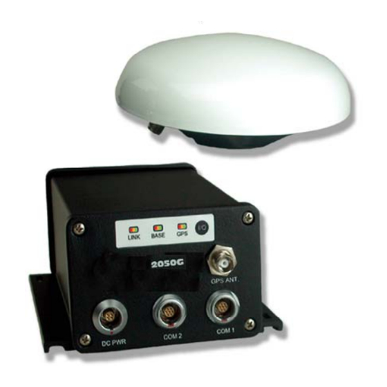
30VDC. Communication Ports The 2050 GPS sensor is fitted with two 7-pin female LEMO connector communication ports located at the bottom front of the GPS sensor as shown in Figure 2 labeled COM1 and COM2. - Page 17 2050 User Guide Figure 2: 2050 Front View Figure 3: 2050M Only Back View...
-
Page 18: Indicator Panel
The Indicator Panel provides the on/off (I/O) switch and a quick view of the status of the 2050 GPS sensor, corrections source & type, and StarFire signal strength. Each of the three indicators has three LEDs, which depict status as detailed in the following tables. - Page 19 2050 User Guide Link LEDs Note – The Link lights are software configurable via the appropriate NCT proprietary command. Because of the numerous scenarios available for the Link light, only the factory default configuration [Rover Mode] is discussed. LINK Status...
-
Page 20: Pps
2050 User Guide GPS LEDs Status Power is off Power is on. No satellites tracked Tracking satellites, position not available yet Non-differential positioning Code based differential positioning Dual frequency Phase positioning Table 5: GPS Light Indication Note – The GPS LEDs will blink at the PVT positioning rate selected (1, 2, 5, 10 and 25 Hz). -
Page 21: Can Bus/Event
2050 User Guide CAN Bus/Event The 2050M also employs CAN Bus technology. CAN bus is a balanced (differential) 2-wire interface, and is ISO11898 -24V compliant. The CAN interface uses an asynchronous transmission scheme. This interface employs a serial binary interchange and is widely used in the automotive industry. - Page 22 2050 User Guide This Page Intentionally left blank 2-14...
-
Page 23: Chapter 3 Installation
2050 User Guide Chapter 3 Installation This chapter provides guidance on how the hardware should be installed for optimum performance. Tri-Mode Antenna The antenna is fitted with a 5/8 inch BSW threaded mount with a depth of 16mm (0.63 inch). -
Page 24: Gps Sensor
2050 User Guide GPS Sensor The 2050 GPS sensor can be mounted to a flat surface using the four screw slots shown in Figure 7. In environments with high vibration, shock absorbers suitable for 1.8kg (4lbs) should be considered. Figure 7: SF-2050 Base Plate Dimensions The 2050 can be installed in a backpack for mobile surveying applications. -
Page 25: Communication Ports
Figure 8: Communication Port Connections Note – By factory default COM 2 is designated as the control port for the 2050. COM 1 can be designated as the control port by using the appropriate NCT proprietary commands. Although some output data types cannot output on the controlling port –... -
Page 26: Gps Antenna Connector
2050 User Guide GPS Antenna Connector The connector used on the 2050 is a TNC female, labeled “GPS ANT” on the front panel of the sensor as shown in Figure 2. Note – The center pin of the TNC connector carries a voltage of 4.4 VDC (nominally), which is used to power the preamplifier in the GPS antenna. -
Page 27: Chapter 4 Configuration
By factory default, COM 2 is designated as the Control Port. The Control Port manages the full functionality of the 2050. COM 1, by factory default, is designated as the Data Port. By factory default this port handles the non-NCT proprietary messages that are input and/or output to/from the receiver. -
Page 28: Advanced Configuration Settings
B1 PVT: Provides GPS Week number, satellites used, latitude, longitude, navigation mode, and DOP information. Note – The term “On Change” indicates that the 2050 will output the specified message only when the information in the message changes and can be dependant on the Navigation Solution Data Rate in use. -
Page 29: Chapter 5 Safety Instructions
All original packaging should be used when transporting via rail, ship or air. Maintenance The 2050 equipment can be cleaned using a new lint free cloth that may be moistened with pure alcohol. Connectors must be inspected and if necessary cleaned before use. Always use the provided connector protective caps to minimize moisture and dirt ingress. -
Page 30: Safety First
There are no user serviceable parts inside the 2050 GPS sensor. Accessing the inside of the equipment will void the equipment warranty. Care should be taken to ensure that the 2050 does not come into contact with electrical power installations, the unit is securely fastened and there is protection against electromagnetic discharge in accordance with local regulations. -
Page 31: Appendix A: Gps Sensor Technical Specifications
2050 User Guide Appendix A: GPS Sensor Technical Specifications The technical specifications of this unit are detailed below and is constantly improving, and updating by our technology improvement process and engineering effort. 2050G and 2050M These GPS sensors are fitted with an internal Lithium coin cell used to maintain GPS time when power is removed from the unit. - Page 32 2050 User Guide Measurement Performance • Real-time StarFire DGPS Accuracy: Position (H): <15 cm Position (V): <30 cm Velocity: 0.01 m/s • Pseudo-range Measurement Precision (RMS): Raw C/A code : 20cm @ 42 dB-Hz Raw carrier phase noise: L1: 0.95 mm @ 42 dB-Hz L2: 0.85 mm @ 42 dB-Hz...
-
Page 33: Led Display Functions (Default)
RTCM 1 or 9 Satellite Based Aumentation Systems StarFire LED Display Functions (Default) • Link StarFire Signal Strength (Default) • Base Station N/A in 2050 ROVER • GPS Position Quality Satellite Based Augmentation System Signals • WAAS/EGNOS/MSAS etc… • StarFire A-25... - Page 34 2050 User Guide This Page Intentionally left blank A-26...
-
Page 35: Appendix B:gps Antenna Technical Specifications
2050 User Guide Appendix B:GPS Antenna Technical Specifications The standard antenna supplied with the 2050 GPS sensor is capable of Tri-Frequency reception. L1+L, L2 GPS Antenna 1525-1585 MHz GPS L1 plus Inmarsat L Band 1217-1237 MHz GPS L2 Polarization Right Hand Circular (RHCP) - Page 36 2050 User Guide Designed to DO-160D Standard Figure 9: Tri-Mode Antenna Dimensions Note – In order to achieve the greatest level of accuracy, the absolute phase center values must be incorporated into your processing. B-28...
-
Page 37: Appendix C:global Corrected Gps (Gcgps)
2050 User Guide Appendix C:Global corrected GPS (GcGPS) Description The StarFire™ Network is a Global system for the distribution of GPS corrections giving the user the ability to measure his position anywhere in the world with exceptional reliability and unprecedented decimeter accuracy. Because the Wide Area Differential GPS corrections are broadcast via Inmarsat geo-stationary communication satellites, the user needs no local reference stations or post-processing to get this exceptional accuracy. - Page 38 Each L-Band satellite covers more than a third of the earth. Users equipped with a C-Nav precision GPS receiver actually have two receivers in a single package, a GPS receiver and an L-Band communications receiver, both designed by NavCom for this system.
- Page 39 The network is a fully automated self-monitoring system. To ensure overall system integrity, an independent integrity monitor receiver, similar to a standard C-Nav or StarFire user receiver, is installed at every reference station to monitor service quality. Data from these integrity monitors is sent to the two independent processing hubs in Torrance, California and Moline, Illinois.
-
Page 40: How To Access The C-Nav ® / Starfire Service
Number of the C-Nav or StarFire receiver L-Band Module (LBM) to be authorized. This is entered into the receiver using the provided Controller Solution. The only piece of equipment needed to use the system is a C-Nav or StarFire receiver. There are a variety of receivers configured for different applications. - Page 41 Print Name: Date: By requesting C-Nav GPS System Subscription Service activation, the user agrees to abide by the terms and conditions for the use and operation of the C-Nav GPS System and the GcGPS Subscription Service correction signals usage. C&C...
- Page 42 2050 User Guide This Page Intentionally left blank C-34...
- Page 43 2050 User Guide C-35...
- Page 44 2050 User Guide This Page Intentionally left blank C-36...
-
Page 45: Appendix D: Nmea Data Output Message Formats
This appendix only describes the NMEA 0183 sentences that are provided by the C- Nav[2050] GPS Receiver. For a complete guide to the NMEA standard and sentence formats, see the National Marine Electronics Association 0183 Standard for Interfacing Marine Electronics. - Page 46 2050 User Guide Address Field An address field is the first field in a sentence and follows the "$" delimiter, it serves to define the message. Characters within the address field are limited to digits and upper case letters. The address field may not be a null field. Only sentences with the following two types of address fields may be transmitted •...
- Page 47 Data fields contain data associated with the Sentence Identifier code. The format of the Data Field is determined by the Sentence Identifier code format value which for the C-Nav GPS Receiver and the CnC D.U. are as follows:- [Address Field]...
-
Page 48: Alm Nmea Sentence
2050 User Guide ALM NMEA Sentence GPS Almanac Data The ALM sentence provides GPS week number, satellite health and the complete almanac data for one satellite. Multiple messages may be transmitted for each satellite. Example: $GPALM,32,1,01,1273,00,2A53,7B,1845,FD59,A10C1B,75D0A3,BB4C39,0FAD97,16C,000*4B FIELD Description Total Number of messages Message Number Satellite PRN Number –... -
Page 49: Gga Nmea Sentence
8 = Simulator Mode Number of GPS Satellites (SVs) used in solution fix Horizontal Dilution of Precision – HDOP C-Nav GPS Receiver antenna altitude reference to Mean Sea Level (MSL) – see Field 11 below Altitude units – M indicates meters... - Page 50 2050 User Guide The GGA sentence, Field 14 is used as the C-Nav GPS Receiver Reference Identification correction source being used. The format is a four digit integer number i.e.: xxyy Where: xx is the Downlink L-Band Communication Satellite beam in use...
-
Page 51: D.3 Gll Nmea Sentence
2050 User Guide D.3 GLL NMEA Sentence GPS Latitude and Longitude Data The GLL sentence specifies the position fix, time of position fix, and status. Example: $GPGLL,2948.24612,N,09533.52868,W,134126.00,A*1C FIELD Description Latitude in DDMM.mmmmm format (5 decimal places) Direction of Latitude N = North S = South Longitude in DDMM.mmmmm format (5 decimal places) -
Page 52: D.4 Gsa Nmea Sentence
2050 User Guide D.4 GSA NMEA Sentence GPS Mode, Satellites used for navigation, and DOP Data The GSA sentence identifies the GPS position fix modes, the SV’s used for navigation, and the DOP values for the position fix. Example: $GPGSA,A,3,04,05,07,09,10,17,24,30,,,,,2.5,1.1,2.2*38... -
Page 53: Gst Nmea Sentence
Table D. 7 GST Sentence Fields The C-Nav[2050] GPS Receiver uses a conventional weighted least squares algorithm for its position solution. The results of the weighted least squares solution are reported directly to the external interfaces with no additional filtering or smoothing. - Page 54 The following diagram illustrates the Horizontal Error Ellipse values provided by the C-Nav[2050] GPS Receiver in the NMEA GST message. Note – This 1 sigma value can be approximated to an area of probability in which 95% of the horizontal position measurements will lie by multiplying by 2.447.
-
Page 55: Rmc Nmea Sentence
UTC time of position fix in HHMMSS.ss format Status A = Valid V = Warning (the ‘V’ character is output whenever the C-Nav GPS Receiver suspects something is in error or wrong) Latitude in DDMM.mmmmm format (5 decimal places) Direction of Latitude... -
Page 56: Vtg Nmea Sentence
2050 User Guide VTG NMEA Sentence GPS Velocity, Track made good and Ground speed Data The VTG sentence identifies the course over ground (COG) and the speed over ground (SOG). Example: $GPVTG,026.6,T,,M,0.01,N,0.02,K,D*61 FIELD Description Course over Ground (COG), in degrees from True North Letter ‘T”... -
Page 57: Zda Nmea Sentence
2050 User Guide ZDA NMEA Sentence GPS UTC Date & Time Data The ZDA sentence identifies the UTC time, the UTC date, the local time zone number, and the local time zone minutes. Example: $GPZDA,124215,02,06,2004,00,00*4B FIELD Description UTC time in HHMMSS.ss format... - Page 58 2050 User Guide This Page Intentionally left blank C-50...
-
Page 59: Appendix E: Starfire L-Band Correction Signal Selection
2050 User Guide Appendix E: StarFire L-Band Correction Signal Selection The C-Nav[2050] GPS Receiver can obtain the C-Nav Global corrected GPS (GcGPS) subscription service signals from three (3) separate and independent geo-stationary communication satellites. While the Satellite Based Augmentation System (S.B.A.S.) from geo-stationary communication satellites, and are selected by GPS L1 PRN ID. - Page 60 2050 User Guide This Page Intentionally left blank C-52...
-
Page 61: Appendix F: How To Log Raw Gps 'Binary' Data From A C-Nav[2050] Unit
C-Nav[2050] GPS system. Note: See the C-Nav FAQ for instructions on how to upload data to the C-Nav FTP site at http://www.cctechnol.com/cnav_faq.php How do I send recorded data files to C-Nav Support for help and analysis? - Page 62 2050 User Guide C-54...
- Page 63 2050 User Guide Enter a ‘filename’ using the actual C-Nav[2050] Serial Number with an extension of .dat C-55...
- Page 64 2050 User Guide C-56...
- Page 65 2050 User Guide C-57...
- Page 66 2050 User Guide This ‘correction age’ is setup for C-Nav RTG corrections. Set to a lower value if using ‘External’ RTCM correction input mode. C-58...
- Page 67 2050 User Guide Select the NMEA data output baud rate required for your Nav or DP system. This is the Com1 (auxillary) RS-232 connection on the front of the C-Nav[2050] unit. C-59...
- Page 68 2050 User Guide External Connect to MS-Windows Connect to Nav party computer running the or DP system correction STARUTIL application. for NMEA Data input option. ( Port B ) Messages. ( Port A ) C-60...
-
Page 69: Glossary
2050 User Guide Glossary .yym files see meteorological files (where yy = two digit year data was collected). .yyn files see navigation files (where yy = two digit year data was collected). .yyo files see observation files (where yy = two digit year data was collected). - Page 70 GPS receiver that uses both L1 and L2 signals from GPS satellites. A dual-frequency receiver can compute more precise position fixes over longer distances and under more adverse conditions because it compensates for ionospheric delays. The 2050 is a dual frequency receiver.
- Page 71 2050 User Guide ellipsoid a mathematical figure approximating the earth’s surface, generated by rotating an ellipse on its minor axis. GPS positions are computed relative to the WGS-84 ellipsoid. An ellipsoid has a smooth surface, which does not match the earth’s geoidal surface closely, so GPS altitude measurements can contain a large vertical error component.
- Page 72 2050 User Guide lat see latitude. latitude (lat) the north/south component of the coordinate of a point on the surface on the earth; expressed in angular measurement from the plane of the equator to a line from the center of the earth to the point of interest.
- Page 73 2050 User Guide PDOP mask the highest PDOP value at which a receiver computes positions. phase center the point in an antenna where the GPS signal from the satellites is received. The height above ground of the phase center must be measured accurately to ensure accurate GPS readings.
- Page 74 2050 User Guide RCP a NavCom Technology, Inc. proprietary processing technique in which carrier phase measurements, free of Ionospheric and Troposphere effects are used for navigation. Real-Time Kinematic (RTK) a GPS system that yields very accurate 3D position fixes immediately in real-time.
- Page 75 2050 User Guide StarFire a set of real-time global orbit and clock corrections for GPS satellites. StarFire equipped receivers are capable of real-time decimeter positioning (see Appendix B). Spread Spectrum Radio (SSR) a radio that uses wide band, noise like (pseudo-noise) signals that are hard to detect, intercept, jam, or demodulate making any data transmitted secure.
Need help?
Do you have a question about the 2050 and is the answer not in the manual?
Questions and answers