Sign In
Upload
Manuals
Brands
C-Nav Manuals
GPS
2050M
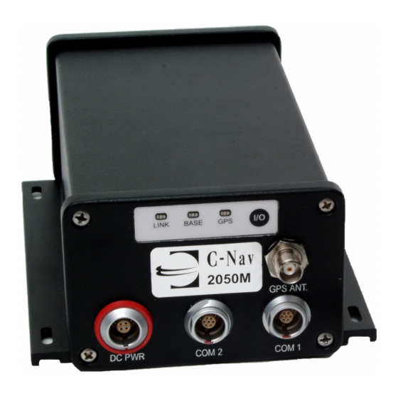
C-Nav 2050M GPS Receiver Manuals
Manuals and User Guides for C-Nav 2050M GPS Receiver. We have
1
C-Nav 2050M GPS Receiver manual available for free PDF download: User Manual
C-Nav 2050M User Manual (166 pages)
Brand:
C-Nav
| Category:
GPS
| Size: 16 MB
Table of Contents
User Guide
1
Quick Start Guide
3
C-Monitor/C-Setup
5
C-Navigator
5
Software Setup
5
How to Enter a C-Nav Service Activation Code
7
C-Setup or C-Monitor
7
C-Navigator
7
Subscription Activation Notes
8
How to Deactivate the C-Nav Service
9
C-Setup or C-Monitor
9
C-Navigator
9
Alternate Method
9
C-Navigator
10
Subscription Deactivation Notes
10
Table of Contents
11
List of Figures
15
Notices
17
Copyright
17
Trademarks
17
FCC Notice
18
User Notice
18
Limited Warranty
18
C-Nav Correction Service Licensing
19
Usg Far
20
Global Positioning System
20
COCOM Limits
21
Revision History
22
Use of this Document
24
Related Documents
25
C-Nav2050 Technical Reference Manual
25
C-Nav Online Resources
25
Related Standards
26
ICD-Gps-200
26
Cmr, Cmr
26
Publicly Operated SBAS Signals
27
Rtca/Do-229D
27
Waas
27
Egnos
27
Msas
27
Gagan
27
Contact Information
28
Chapter 1 Introduction
31
System Overview
31
GPS Receiver System
31
Figure 2: L-Band Antenna (C-Nav2050R Only)
32
Figure 1: C-Nav2050 Supplied Equipment
32
Supplied Equipment
32
Table 1: Supplied Equipment
33
Models
34
C-Nav2050G
34
C-Nav2050M
34
C-Nav2050R
35
Features that Apply to All Models
35
Output Data Rate
35
NCT Binary Proprietary Data
36
NMEA - 0183 Data
36
Antennae
37
Standard
37
Airborne (Option)
38
L-Band (Option - C-Nav2050R Only)
38
Controller
39
Unique Features
39
C-Nav Correction Service
39
Positioning Flexibility
39
RTK Extend
40
Data Sampling
40
GPS Performance
41
Rugged Design
41
Accuracy
41
Figure 3: Power Port Pin Assignment
43
Chapter 2 Interfacing
43
Electrical Power
43
Figure 5: AC Power Cord
44
Figure 6: DC Power Cable Pin Assignments
45
Figure 7: Isolation Mount Adaptors
46
Communication Ports
47
Figure 4: Universal Power Adapter
44
Isolation Mount Adaptor
46
Figure 8: C-Nav 2050 Front View
47
Table 2: Serial Cable Pin-Outs
48
Figure 9A: C-Nav Serial Cable Pin Assignment
48
Figure 9B: C-Nav Serial Cable Pin Assignment
49
Figure 10: C-Nav2050M Back View
51
Event Input Configuration
52
Figure 11: Event Cable Wiring Diagram
52
Table 4: Event Wiring Connections
52
Figure 12: 1PPS & Event Latch Configuration
53
Table 5: Link LED Indication (Default)
54
Base Leds
55
GPS Leds
55
Figure 13: Event Latch Output Rate Configuration
53
Indicator Panel
54
Link Leds
54
Table 3: Acceptable RS-232 Cable Lengths
49
CAN Bus/Event (C-Nav2050M Only)
50
Event
50
Pps
51
Figure 14: C-Nav2050 Indicator Panel
54
Table 6: Base Station Indication
55
Table 7: GPS Light Indication
55
Chapter 3 Installation
57
Standard Antenna
57
Antenna Location
58
Figure 15: Standard GPS/L-Band Antenna
58
Figure 16A: Antenna Mounting Poles
60
Figure 17: Antenna, Adaptor and Mounting Pole
61
Antenna Installation
62
Antenna Mounting Pole Adaptor
61
Antenna Mounting Pole
60
Figure 16B: Antenna Mounting Pole and Adaptor
61
Figure 18: C-Nav2050 Antenna Mast Installation
62
Figure 19: High Latitude L-Band Antenna
63
Cable Route
64
Coaxial Cable
64
Coaxial Cable Installation
65
GPS Receiver
67
Lightning Protection
67
Table 8: Acceptable Coaxial Cable Lengths
67
GPS Receiver Antenna Connector
68
GPS Receiver Location
68
Block Diagrams
69
Figure 20: C-Nav2050G/M Block Diagram
69
Figure 22: C-Nav2050R Block Diagram
70
Communication Port Connectivity
71
Dual Data Interface Cable
72
L-Band Antenna (C-Nav2050R Only)
63
Figure 21: Radio Port Configuration in Starutil
70
Figure 23: Communication Port Connections
72
Figure 24: Dual Data Cable
72
Table 9: Dual Data Interface Cable I/O
73
Figure 25: Dual Data Cable Pin Assignment Diagram
73
Figure 26: Optional Com Port Setup with Dual Data Cable
74
Chapter 4 Configuration
75
Factory Default Settings
76
Com1
76
Figure 27: Starutil NMEA Message List
76
Com2
77
Factory Default Output Messages
78
NCT Binary Messages
78
Message Descriptions
78
Logging Raw/Binary Data Using Starutil
80
Figure 29: Starutil PC Port Configuration
80
Figure 30: NCT Binary Message Output Configuration
81
Figure 31: Starutil Data Logging Utility
82
Logging Raw/Binary Data Using C-Navigator
83
Logging Raw/Binary Data Using C-Setup/C-Monitor
83
Sending Data to C-Nav Support
83
3Rd Party Controller Configuration Settings
85
RTK Rover/Base Station Setup
85
Chapter 5 Safety Instructions
87
Transport
87
Maintenance
87
External Power Source
87
Safety First
88
Appendix A GPS Receiver Specifications
89
Features
89
Time-To-First-Fix (Cold Start
90
Dynamics
90
Measurement Performance
91
User Programmable Output Rates
92
Data Latency
92
1Pps
92
Connector Assignments
93
LED Display Functions (Default
94
Satellite Based Augmentation System Signals
94
Physical and Environmental
94
Figure A1: C-Nav2050 Front Dimensions
95
Figure A2: C-Nav2050 Base Plate Dimensions
95
Appendix B Antenna Specifications
97
Standard Antenna Specifications
97
Figure B1: P/N: 8250001-0 Antenna Dimensions
98
Figure B3: AN-2004T Radiation Pattern
99
Figure B5: C-Nav2050R Antenna Mounts
101
Figure B6: C-Nav2050R Antenna Radiation Pattern
102
L-Band Antenna Radiation Pattern
102
Airborne Antenna Dimensions
103
L-Band Antenna Specifications
100
Standard Antenna Radiation Pattern
99
Figure B4: C-Nav2050R Antenna Dimensions
101
Appendix C C-Nav DGPS Correction Service
105
Description
105
Infrastructure
106
Reliability
107
How to Access the C-Nav Correction Service
108
Figure C1: C-Nav Correction Service Network
110
Appendix D NMEA Data Output Messages
111
Gpalm
111
Table D1: ALM Output Format
111
Gpgbs
112
Table D2: GBS Output Format
112
Gpgga
113
Table D3: GGA Output Format
113
Gpgll
116
Table D4: GLL Output Format
116
Gpgrs
117
Table D5: GRS Output Format
117
Gpgsa
118
Table D6: GSA Output Format
118
Gpgst
119
Table D7: GST Output Format
119
Gpgsv
120
Table D8: GSV Output Format
120
Gprmc
121
Table D9: RMC Output Format
121
Gpvtg
122
Table D10: VTG Output Format
122
Gpzda
123
Table D11: ZDA Output Format
123
Pnctset
124
Table D12: SET Output Format
124
Appendix E Certificates
125
Certificate of Registration
125
Certificate of Type Approval
127
Ministry of Transportation of the Russian Federation Certificate of Type Approval
130
Appendix F C-Nav L-Band Correction Signal
131
Table F1: L-Band Correction Identifiers and Modes
131
Appendix G Glossary
133
Abbreviations
133
Definitions
137
Figure G1: DTE to DCE RS-232 Pin Assignments
143
Appendix H Index
159
Advertisement
Advertisement
Related Products
C-Nav 2050
C-Nav C-NaviGator III
C-Nav iGator III
C-Nav Categories
Car Navigation system
GPS
Boating Equipment
Control Unit
More C-Nav Manuals
Login
Sign In
OR
Sign in with Facebook
Sign in with Google
Upload manual
Upload from disk
Upload from URL