
Related Manuals for Emerson EWD7003


Summary of Contents for Emerson EWD7003
-
Page 1: Dvd Player
SERVICE MANUAL This service manual supplement (EWD7003) contains only the difference from the original model. For all other data, see the original service manual for DVL700D. DVD PLAYER EWD7003... -
Page 2: Table Of Contents
IMPORTANT SAFETY NOTICE Proper service and repair is important to the safe, reliable operation of all Funai Equipment. The service procedures recommended by Funai and described in this service manual are effective methods of performing service operations. Some of these service special tools should be used when and as recommended. -
Page 3: Operating Controls And Functions
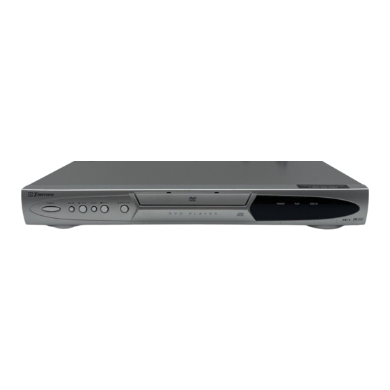
OPERATING CONTROLS AND FUNCTIONS FRONT PANEL REAR VIEW AUDIO OUT COMPONENT VIDEO OUT DIGITAL AUDIO OUT PCM/ BITSTREAM COAXIAL VIDEO S-VIDEO OUT 1. POWER 10. DISC IN Indicator to switch the player to ON or OFF light appears when a disc is in the DVD player. 2. -
Page 4: Block Diagrams
BLOCK DIAGRAMS System Control/Servo Block Diagram SLED SERVO SIGNAL SPINDLE SERVO SIGNAL FOCUS SERVO SIGNAL TRACKING SERVO SIGNAL IC101 (MICRO CONTROLLER) EXT CLOCK CLK33M BE CLOCK IC202 IC451 (OP AMP) (CLOCK GENERATOR) X451 POFLT MULTI X'TAL 36.864MHz PLL2 FSEL PCM-SCLK A-MUTE A-MUTE ADAC-MD... -
Page 5: Digital Signal Process Block Diagram
Digital Signal Process Block Diagram DATA(AUDIO) SIGNAL DATA(VIDEO/AUDIO) SIGNAL VIDEO SIGNAL FOCUS SERVO SIGNAL TRACKING SERVO SIGNAL IC102 (SDRAM) IC101 (MICRO CONTROLLER) SDRAM ADDRESS(0-10) SDRAM ADDRESS(0-10) DATA SDRAM EXTERNAL MEMORY DECODER INST. DECODER STREAM SDRAM DATA(0-31) SDRAM DATA(0-31) DATA PIXEL OPERATION INST. - Page 6 Video / Audio Block Diagram DATA(AUDIO) SIGNAL AUDIO SIGNAL VIDEO SIGNAL IC1402 (VIDEO DRIVER) DRIVER JK1401 S-VIDEO OUT DRIVER CN601 CN1601 DRIVER VIDEO-Y VIDEO-Y FROM DIGITAL VIDEO-C VIDEO-C JK1404 SIGNAL PROCESS VIDEO-Cb BLOCK DIAGRAM VIDEO-Cb DRIVER COMPOSITE VIDEO-Cr VIDEO-Cr VIDEO OUT DRIVER VIDEO-Y VIDEO-Cb...
-
Page 7: Power Supply Block Diagram
Power Supply Block Diagram CAUTION ! CAUTION Fixed voltage ( or Auto voltage selectable ) power supply circuit is used in this unit. FOR CONTINUED PROTECTION AGAINST FIRE HAZARD, NOTE : If Main Fuse (F1001) is blown, check to see that all components in the power supply REPLACE ONLY WITH THE SAME TYPE FUSE. -
Page 8: Schematic Diagrams / Cba's And Test Points
SCHEMATIC DIAGRAMS / CBA’S AND TEST POINTS Standard Notes WARNING Many electrical and mechanical parts in this chassis have special characteristics. These characteristics often pass unnoticed and the protection afforded by them cannot necessarily be obtained by using replace- ment components rated for higher voltage, wattage, etc. - Page 9 LIST OF CAUTION, NOTES, AND SYMBOLS USED IN THE SCHEMATIC DIAGRAMS ON THE FOLLOWING PAGES: 1. CAUTION: FOR CONTINUED PROTECTION AGAINST FIRE HAZARD, REPLACE ONLY WITH THE SAME TYPE FUSE. ATTENTION: POUR UNE PROTECTION CONTINUE LES RISQES D'INCELE N'UTILISER QUE DES FUSIBLE DE MÊME TYPE.
- Page 10 DVD Main 1/3 Schematic Diagram SPINDLE SERVO SIGNAL DATA(VIDEO+AUDIO) FOCUS SERVO SIGNAL TRACKING SERVO SIGNAL SLED SERVO SIGNAL DVD MAIN 1/3 Ref No. Position IC201 IC202 IC301 IC461 TRANSISTORS Q251 Q252 Q253 Q254 CONNECTORS CN201 CN301 CN401 1-3-3 1-3-4 E57T0SCD1...
- Page 11 DVD Main 2/3 Schematic Diagram DATA(VIDEO+AUDIO) FOCUS SERVO SIGNAL SPINDLE SERVO SIGNAL DATA (AUDIO) VIDEO SIGNAL TRACKING SERVO SIGNAL SLED SERVO SIGNAL DVD MAIN 2/3 Ref No. Position IC101 CONNECTORS CN204 1-3-5 1-3-6 E57T0SCD2...
- Page 12 IC101 VOLTAGE CHART PIN.NO PLAY STOP PIN.NO PLAY STOP PIN.NO PLAY STOP PIN.NO PLAY STOP PIN.NO PLAY STOP PIN.NO PLAY STOP PIN.NO PLAY STOP PIN.NO PLAY STOP ----- ----- ----- ----- ----- ----- ----- ----- ----- ----- ----- ----- ----- ----- ----- -----...
- Page 13 DVD Main 3/3 Schematic Diagram VIDEO SIGNAL DATA (AUDIO) AUDIO SIGNAL DVD MAIN 3/3 Ref No. Position IC102 IC103 IC104 IC105 IC451 IC601 CONNECTOR CN601 1-3-9 1-3-10 E57T0SCD3...
- Page 14 AV 1/3 Schematic Diagram CAUTION CAUTION ! NOTE : FOR CONTINUED PROTECTION AGAINST FIRE HAZARD, Fixed voltage ( or Auto voltage selectable ) power supply circuit is used in this unit. The voltage for parts in hot circuit is measured REPLACE ONLY WITH THE SAME TYPE FUSE.
- Page 15 AV 2/3 Schematic Diagram VIDEO SIGNAL DATA (AUDIO) AUDIO SIGNAL AV 2/3 Ref No. Position IC1201 IC1402 TRANSISTORS Q1201 Q1202 Q1203 Q1204 Q1351 Q1352 CONNECTOR CN1601 1-3-13 1-3-14 E57T0SCAV2...
- Page 16 AV 3/3 & Function Schematic Diagram AV 3/3 Ref No. Position IC2001 TRANSISTORS Q2001 Q2003 CONNECTORS JP2001 1-3-15 1-3-16 E57T0SCAV3...
- Page 17 AV CBA Top View CAUTION ! NOTE : Fixed voltage ( or Auto voltage selectable ) power supply circuit is used in this unit. The voltage for parts in hot circuit is measured If Main Fuse (F1001) is blown, check to see that all components in the power supply using hot GND as a common terminal.
- Page 18 AV CBA Bottom View CAUTION ! NOTE : Fixed voltage ( or Auto voltage selectable ) power supply circuit is used in this unit. The voltage for parts in hot circuit is measured If Main Fuse (F1001) is blown, check to see that all components in the power supply using hot GND as a common terminal.
- Page 19 FUNCTION CBA Top View FUNCTION CBA Bottom View 1-3-21 1-3-22 BE57S0F01013...
-
Page 20: Waveforms
WAVEFORMS Pin 5 of CN1601 Pin 13 of CN1601 NOTE: Input CD: 1kHz PLAY (WF4~WF6) DVD: POWER ON (STOP) MODE (WF1~WF3) VIDEO-Y 0.2V 20µsec AUDIO-R 0.5msec Pin 7 of CN1601 Pin 16 of CN1601 VIDEO-C 0.2V 20µsec SPDIF 0.1µsec Pin 21 of IC1402 VIDEO-CVBS 0.5V 20µsec... -
Page 21: Wiring Diagram
WIRING DIAGRAM VIDEO-Y VIDEO-Cb VIDEO-Cr VIDEO AUDIO-L AUDIO-R DIGITAL S-VIDEO AC CORD AUDIO OUT JP2001 JP2002 KEY-2 FUNCTION CBA AV CBA (BE57S0F01013) (BE57S0F01013) KEY-4 KEY-3 KEY-1 CN1001 CN1601 CN401 CN601 DVD MAIN CBA UNIT CN301 CN201 CN204 (NO CONNECTION) SLED MOTOR SENSOR SPINDLE... -
Page 22: Mechanical Parts List
MECHANICAL PARTS LIST PRODUCT SAFETY NOTE: Products marked with a # have special characteristics important to safety. Before replacing any of these components, read care- fully the product safety notice in this service manual. Don't degrade the safety of the product through improper servicing. -
Page 23: Electrical Parts List
ELECTRICAL PARTS LIST PRODUCT SAFETY NOTE: Products marked with a Ref. No. Description Part No. # have special characteristics important to safety. C1035 ELECTROLYTIC CAP . 470µF/16V M CE1CMASDL471 Before replacing any of these components, read care- C1036 CHIP CERAMIC CAP . B K 0.01µF/50V CHD1JK30B103 fully the product safety notice in this service manual. - Page 24 Ref. No. Description Part No. Ref. No. Description Part No. D1005 RECTIFIER DIODE 1N4005 NDQZ001N4005 L1043 BEAD CORE B16 RH 4X3X2 XL03003XM001 D1006 SCHOTTKY BARRIER DIODE SB140 or NDQZ000SB140 L1060 BEAD CORE B16 RH 3.5X3X1.3 XL03003XM002 SCHOTTKY BARRIER DIODE ERA81-004 QDPZERA81004 L1350 INDUCTOR 100µH-K-26T...
- Page 25 Ref. No. Description Part No. Ref. No. Description Part No. CHIP RES.(1608) 1/10W J 5.6k Ω CHIP RES.(1608) 1/10W J 220 Ω R1021 RRXAJR5Z0562 R1354 RRXAJR5Z0221 CHIP RES.(1608) 1/10W J 820 Ω CHIP RES.(1608) 1/10W J 75 Ω R1022 RRXAJR5Z0821 R1355 RRXAJR5Z0750 CHIP RES.(1608) 1/16W F 2.4k Ω...
- Page 26 Ref. No. Description Part No. W1001 22P FFC AV PCB TO MAIN WX1E57S0-002 W1601 16P FFC WX1E57S0-001 FUNCTION CBA Ref. No. Description Part No. FUNCTION CBA ---------- Consists of the followings RESISTORS CHIP RES.(1608) 1/10W 0 Ω R2011 RRXAZR5Z0000 CHIP RES.(1608) 1/10W 0 Ω R2012 RRXAZR5Z0000 CHIP RES.(1608) 1/10W 0 Ω...
- Page 27 Printed in Japan 2003-04-06 HO...
Need help?
Do you have a question about the EWD7003 and is the answer not in the manual?
Questions and answers