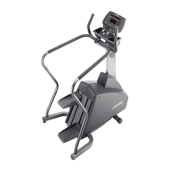
Life Fitness 95SE Assembling Instructions
Stairclimber
Hide thumbs
Also See for 95SE:
- Parts manual (16 pages) ,
- Service manual (126 pages) ,
- Specification (24 pages)
Advertisement
Advertisement
Table of Contents

Related Manuals for Life Fitness 95SE


Summary of Contents for Life Fitness 95SE
- Page 1 95Se Stairclimber A s s e m b l y I n s t r u c t i o n s...
- Page 2 Congratulations... and welcome to the world of The following Parts Identification Listing and the step by step assembly procedures have been assembled to make the set-up of the Stairclimber as quick and easy as possible. Please take special note of the following important points prior to choosing a location and beginning assembly of the Stairclimber.
- Page 3 Stairclimber outdoors, near swimming pools, or in areas of high humidity. ⇒ DO NOT operate your Stairclimber if it has been dropped, damaged, or even partially immersed in water. If this occurs, contact Life Fitness Customer Support Services at the number in the Operation Manual. ⇒ DO NOT locate the Stairclimber any closer than 30 inches ( 76 cm ) to a television set.
- Page 4 OOLS EQUIRED FOR Hex Head Bolt 3/8 – 16 x 3 Hex Head Bolt 5/16 – 18 x 1.500 Phillips Pan Head Screw #8 – 18 x .625 Phillips Pan Head Screw #8 – 18 x .75 Display Console Assembly Accessory Tray Left Bullhorn Handlebar Handlebar Assembly...
- Page 5 1. Before proceeding, familiarize yourself with the parts of the Stairclimber and make sure that you have received all the items described in the Parts List. 2. Locate the MONOCOLUMN (#10). Position the MONOCOLUMN SHROUD (#16) onto the MONOCOLUMN as shown. Position the MONOCOLUMN near the MONOCOLUMN MOUNTING BRACKET (A) as shown.
- Page 6 Locate the USER LEFT BULLHORN (#13) with a Lifepulse sensor. Connect the 2-PIN CONNECTOR (2P) leading from the USER LEFT BULLHORN to the 2-PIN CONNECTOR (2PL) now leading from the HANDLEBAR BRACKET TUBE (E). Carefully feed any excess HEART RATE CABLE (2PL) into the HANDLEBAR BRACKET TUBE and secure the USER LEFT BULLHORN to the HANDLEBAR BRACKET TUBE using three MOUNTING SCREWS (#6).
- Page 7 Using four MOUNTING SCREWS (#5), attach the ACCESSORY TRAY (#11) to the DISPLAY CONSOLE (#9) as shown. CAUTION: Do not over-tighten the SCREWS (#5). MISE EN GARDE : Ne serrez pas trop les VIS (Nº 5). Attach all CABLES (H, CX) leading from the DISPLAY CONSOLE MOUNTING BRACKET (C) ACCESS HOLE to the back of the DISPLAY CONSOLE (#9).
- Page 8 Manual, contact the nearest Life Fitness service center as listed in the Operation Manual. ©2003 Life Fitness, a division of Brunswick Corporation. All rights reserved. Life Fitness is trademark of Brunswick Corporation. Polar is a registered trademark of Polar Electro, Inc.
Need help?
Do you have a question about the 95SE and is the answer not in the manual?
Questions and answers