Sign In
Upload
Download
Add to my manuals
Delete from my manuals
Share
URL of this page:
HTML Link:
Bookmark this page
Add
Manual will be automatically added to "My Manuals"
Print this page
×
Bookmark added
×
Added to my manuals
Manuals
Brands
Panasonic Manuals
Network Hardware
K-NL304K/G
Quick start manual
Panasonic K-NL304K/G Quick Start Manual
Hide thumbs
1
2
3
4
5
6
7
8
9
10
11
12
13
14
15
16
17
18
19
20
page
of
20
Go
/
20
Bookmarks
Advertisement
Quick Links
Download this manual
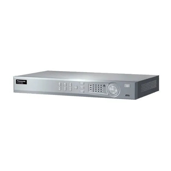
Network Video Recorder
Quick Start Guide
K-NL304K/G
Model No.
K-NL308K/G
Version 1.0.0
Previous
Page
Next
Page
1
2
3
4
5
Advertisement
Need help?
Do you have a question about the K-NL304K/G and is the answer not in the manual?
Ask a question
Questions and answers
Related Manuals for Panasonic K-NL304K/G
Network Hardware Panasonic K-NL308K/G Quick Start Manual
(20 pages)
Network Hardware Panasonic k-nl304g User Manual
(198 pages)
Network Hardware Panasonic WJNT304 - NETWORK INTERFACE UNIT Network Operating Instructions
Network interface unit (60 pages)
Network Hardware Panasonic WJ-NT104 Operating Instructions Manual
Network interface unit (84 pages)
Network Hardware Panasonic WJ-SX850 Instructions Manual
Matrix switcher card cage (8 pages)
Network Hardware Panasonic K-NL408KT/G Quick Start Manual
(32 pages)
Network Hardware Panasonic K-NL404K/G Quick Start Manual
(32 pages)
Network Hardware Panasonic GA-ML Series Manual
(198 pages)
Network Hardware Panasonic K-NL408KT/G User Manual
Network disk recorder (245 pages)
Network Hardware Panasonic BN-SW60ANL0 User Manual
Dtl wireless link wireless unit (9 pages)
Network Hardware Panasonic WJ-NT314 Network Operating Instructions
Network interface unit (71 pages)
Network Hardware Panasonic Network Adaptor Specification Sheet
Programmable controller (8 pages)
Network Hardware Panasonic RD-AA8190-01 Instruction Manual
Enhanced cell modem (22 pages)
Network Hardware Panasonic PN261693D Manual
(195 pages)
Network Hardware Panasonic E series Operation Manual
(12 pages)
This manual is also suitable for:
K-nl308k/g
Print
Rename the bookmark
Delete bookmark?
Delete from my manuals?
Login
Sign In
OR
Sign in with Facebook
Sign in with Google
Upload manual
Upload from disk
Upload from URL


Need help?
Do you have a question about the K-NL304K/G and is the answer not in the manual?
Questions and answers