Table of Contents
Advertisement
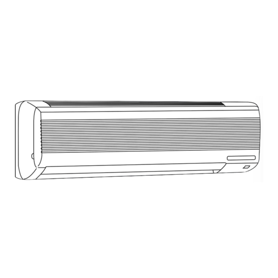
SPLIT-TYPE,HEAT PUMP AIR CONDITIONERS
SERVICE MANUAL
Wireless type
Models
MS-07NV -
MS-09NV -
MS-12NV -
MS-18NV -
MS-24NV -
MS-07NV -
MS-09NV -
MS-12NV -
MS-18NV -
MS-24NV -
MS-18NV -
MS-18NV -
E1
MS-24NV -
E1
MS-18NV -
E2
MS-24NV -
E2
MS-18NV -
E3
This Servise Manual OB206 deals with MS-07/09/12/18/24NV-E1,
MU-07/09/12/18/24NV-E1, MS-18NV-E2, and MU-18NV-E2 in
OB175 THIRD EDITION issued in June in 1997.
Therfore, please refer to OB206, not to OB175 THIRD EDITION,
for the above models.
· MU-07NV -
( WH )
E1
· MU-09NV -
( WH )
E1
· MU-12NV -
( WH )
E1
· MU-18NV -
( WH )
E1
· MU-24NV -
( WH )
E1
· MU-07NV -
( WH )
E2
· MU-09NV -
( WH )
E2
· MU-12NV -
( WH )
E2
· MU-18NV -
( WH )
E2
· MU-24NV -
( WH )
E2
· MU-18NV -
( WH )
E3
CONTENTS
1. TECHNICAL CHANGES ····································2
2. PART NAMES AND FUNCTIONS······················3
3. SPECIFICATION·················································6
4. OUTLINES AND DIMENSIONS ·························9
5. WIRING DIAGRAM ··········································12
6. REFRIGERANT SYSTEM DIAGRAM ··············20
7. PERFORMANCE CURVES ······························24
8. MICROPROCESSOR CONTROL ····················27
9. SERVICE FUNCTIONS ····································34
10. TROUBLESHOOTING······································37
11. DISASSEMBLY INSTRUCTIONS·····················45
12. PARTS LIST······················································53
13. OPTIONAL PARTS···········································61
No. OB206
E1
E1
E1
E1
E1
E2
E2
E2
E2
E2
E3
Advertisement
Table of Contents

Related Manuals for Mitsubishi Electric MS-07NV -E1 (WH)


Summary of Contents for Mitsubishi Electric MS-07NV -E1 (WH)
-
Page 1: Table Of Contents
This Servise Manual OB206 deals with MS-07/09/12/18/24NV-E1, MU-07/09/12/18/24NV-E1, MS-18NV-E2, and MU-18NV-E2 in OB175 THIRD EDITION issued in June in 1997. Therfore, please refer to OB206, not to OB175 THIRD EDITION, for the above models. SPLIT-TYPE,HEAT PUMP AIR CONDITIONERS No. OB206 SERVICE MANUAL Wireless type Models... -
Page 2: Technical Changes
TECHNICAL CHANGES MS-07NV - MS-07NV - 1. Indoor electronic control P.C. board has changed. However, it is compatible between models. 2. Auto restart function is added. MS-09NV - MS-09NV - 1. Indoor electronic control P.C. board has changed. However, it is compatible between models. -
Page 3: Part Names And Functions
PART NAMES AND FUNCTIONS INDOOR UNIT MS-07NV - MS-09NV - MS-12NV - MS-18NV - MS-07NV - MS-09NV - MS-12NV - MS-24NV - MS-18NV - MS-24NV - MS-18NV - (When the front panel is open) MS-07NV - MS-09NV - MS-12NV - MS-07NV - MS-09NV - MS-12NV -... - Page 4 MS-07NV - MS-09NV - MS-12NV - MS-18NV - MS-24NV - MS-18NV - REMOTE CONTROLLER...
- Page 5 MS-07NV - MS-09NV - (Product number 7000001T~) (Product number 7000001T~) MS-12NV - MS-24NV - (Product number 7000001T~) (Product number 7000001T~) MS-07NV - MS-09NV - MS-12NV - MS-18NV - (Product number 7000001T~) MS-24NV - MS-18NV -...
-
Page 6: Specification
SPECIFICATION Model MS-07NV - MS-09NV - Function Cooling Cooling Power supply Single phase,220-240V,50Hz Capacity Capacity Dehumidification K /h Air flow INDOOR 492 OUTDOOR 1620 Power outlet 3.15-3.05 3.60-3.45 Running current Power input 680-710 780-810 Auxiliary heater A(kW) — Electrical data 98-97 98-98 Power factor... - Page 7 MS-09NV - Model MS-12NV - Function Cooling Cooling Power supply Single phase,220-240V,50Hz Capacity Capacity Dehumidification INDOOR 492 OUTDOOR 1620 Air flow K /h INDOOR 558 OUTDOOR 2190-2304 Power outlet 3.60-3.45 Running current 6.20-6.35 780-810 Power input 1310-1390 Auxiliary heater A(kW) —...
- Page 8 Model MS-18NV - MS-24NV - Function Cooling Cooling Power supply Single phase,220-240V,50Hz Capacity Capacity Dehumidification INDOOR 816 OUTDOOR 2286 K /h INDOOR 756 OUTDOOR 2190 Air flow Power outlet 12.9-12.6 Running current 2,780-2,900 1,910-2,010 Power input — Auxiliary heater A(kW) 98-96 Electrical data 95-92...
-
Page 9: Outlines And Dimensions
OUTLINES AND DIMENSIONS MS-07NV - MS-09NV - Unit : mm MS-07NV - MS-09NV - INDOOR UNIT MU-07NV - MU-09NV - MU-07NV - MU-09NV - OUTDOOR UNIT... -
Page 10: Indoor Unit
MS-12NV - MS-12NV - Unit : mm INDOOR UNIT MU-12NV - MU-12NV - OUTDOOR UNIT If the right/left sides or back side is vacant,the front has only to be 50cm unobstructed. 12.7... - Page 11 Unit : mm MS-18NV - MS-24NV - 4holes 1 4holes 11 1 20 Indoor unit Indoor unit MS-18NV - MS-24NV - MS-18NV - INDOOR UNIT W W all hole all hole [ [ 75 Installation plate Installation plate 1015 1015 Installation plate Installation plate Liquid line...
-
Page 12: Wiring Diagram
WIRING DIAGRAM MS-07NV - MODELS WIRING DIAGRAM MS-09NV - INDOOR UNIT NAME SYMBOL SYMBOL NAME SYMBOL NAME INDOOR FAN CAPACITOR NR11 VARISTOR TERMINAL BLOCK FUSE(93:) ROOM TEMPERATURE THERMISTOR VANE MOTOR RT11 FUSE(3.15A) INDOOR COIL THERMISTOR SOLID STATE RELAY RT12 SR11 INDOOR FAN MOTOR HIC1 DC/DC CONVERTER... - Page 13 MS-12NV - MODEL WIRING DIAGRAM INDOOR UNIT NAME SYMBOL SYMBOL NAME SYMBOL NAME INDOOR FAN CAPACITOR VARISTOR TERMINAL BLOCK NR11 FUSE(93:) ROOM TEMPERATURE THERMISTOR VANE MOTOR RT11 FUSE(3.15A) INDOOR COIL THERMISTOR SOLID STATE RELAY RT12 SR11 INDOOR FAN MOTOR HIC1 DC/DC CONVERTER CONTACTOR NOTE:1.
- Page 14 MS-18NV - MODEL WIRING DIAGRAM INDOOR UNIT RT12 IC141 TO OUTDOOR CN201 UNIT CONNECTING CN211 RT11 ELECTRONIC CONTROL P.C BOARD POWER SUPPLY CORD RECEIVER DISPLAY 220-240V P.C.BOARD P.C.BOARD 50Hz GRN/YLW REMOTE CONTROLLER SYMBOL NAME SYMBOL NAME SYMBOL NAME INDOOR FAN CAPACITOR VARISTOR TERMINAL BLOCK NR11...
- Page 15 MS-24NV - MODEL WIRING DIAGRAM INDOOR UNIT 220-240V~ RT12 HIC1 IC141 220-240V~ TO OUTDOOR CN201 UNIT CN211 TRANS CONNECTING POWER SUPPLY ELECTRONIC CONTROL P.C BOARD RT11 CORD ~/N 220-240V 50Hz DISPLAY RECEIVER CIRCUIT BREAKER P.C.BOARD P.C.BOARD GRN/YLW REMOTE CONTROLLER SYMBOL NAME SYMBOL NAME...
- Page 16 MS-07NV - MS-09NV - MS-12NV - MODELS WIRING DIAGRAM INDOOR UNIT SR11 RT12 HIC1 TO OUTDOOR RT11 UNIT CONNECTING CN201 NR11 220-240V~ TRANS CN211 LD101 GUARD ELECTRONIC CONTROL P.C BOARD PLATE POWER SUPPLY CORD ~/N 220-240V POWER MONITOR, 50Hz RECEIVER P.C.BOARD CIRCUIT BREAKER REMOTE...
- Page 17 MS-18NV - MODEL WIRING DIAGRAM INDOOR UNIT SYMBOL NAME SYMBOL NAME SYMBOL NAME INDOOR FAN CAPACITOR NR11 VARISTOR TERMINAL BLOCK FUSE(93¡C) ROOM TEMPERATURE THERMISTOR SURGE ABSORBER RT11 DSAR FUSE(3.15A) INDOOR COIL THERMISTOR DC / DC CONVERTER RT12 HIC1 INDOOR FAN MOTOR HYBRID IC IC141 VANE MOTOR...
- Page 18 MS-24NV - MODEL WIRING DIAGRAM INDOOR UNIT RT12 220-240V~ HIC1 IC141 220-240V~ TO OUTDOOR CN201 UNIT CN211 TRANS CONNECTING POWER SUPPLY ELECTRONIC CONTROL P.C BOARD RT11 CORD ~/N 220-240V 50Hz DISPLAY RECEIVER CIRCUIT BREAKER P.C.BOARD P.C.BOARD GRN/YLW REMOTE CONTROLLER SYMBOL NAME SYMBOL NAME...
- Page 19 MS-18NV - MODEL WIRING DIAGRAM INDOOR UNIT RT12 T O OUTDOOR HIC1 IC141 UNIT CONNECTING 220-240V~ CN201 CN211 TRANS POWER SUPPLY RT11 ELECTRONIC CONTROL P.C BOARD CORD ~/N 220-240V 50Hz DISPLAY RECEIVER CIRCUITBREAKER P.C.BOARD P.C.BOARD GRN/YLW REMOTE CONTROLLER SYMBOL NAME SYMBOL NAME SYMBOL...
-
Page 20: Refrigerant System Diagram
REFRIGERANT SYSTEM DIAGRAM Unit:mm MS-07NV - MS-09NV - MU-07NV - MU-09NV - MS-07NV - MS-09NV - MU-07NV - MU-09NV - Refrigerant pipe [9.52 OUTDOOR UNIT INDOOR UNIT (Option) (with heat insulator) Stop valve (with service port) Indoor coil Indoor Outdoor thermistor heat heat... - Page 21 Unit:mm MS-18NV - MS-18NV - MU-18NV - MU-18NV - MS-18NV - MU-18NV - OUTDOOR UNIT INDOOR UNIT Refrigerant pipe [15.88 (Option) (with heat insulator) Accumulator Indoor coil Stop valve Indoor Outdoor thermistor (with service port) heat heat RT12 exchanger exchanger Strainer Distributor Flared...
- Page 22 MAX. REFRIGERANT PIPING LENGTH Refrigerant piping Piping size O.D : mm Length of connecting pipe : m Model Max. length : m Liquid Indoor unit Outdoor unit MS-07NV - MS-07NV - 9.52 MS-09NV - 6.35 MS-09NV - MS-12NV - 12.7 0.43 MS-12NV - MS-18NV -...
- Page 23 EVACUATION PROCEDURES(AIR PURGE) Connect the refrigerant pipes (both the liquid and gas pipes) between the indoor and the outdoor units. Remove the service port cap of the stop valve on the side of the outdoor unit gas pipe (The stop valve will not work in its initial state fresh out of the factory (totally closed with cap on)).
-
Page 24: Performance Curves
PERFORMANCE CURVES The standard data contained in these specifications apply only to the operation of the air conditioner under normal conditions. Since operating conditions vary according to the areas where these units are installed. The following information has been provided to clarify the operating characteristics of the air conditioner under the conditions indicated by the performance curve. (1) GUARANTEED VOLTAGE Rated voltage : ±10% (198 ~ 264V ),50Hz (2) AIR FLOW... - Page 25 OUTDOOR LOW PRESSURE AND OUTDOOR UNIT CURRENT COOL operation Both indoor and outdoor unit are under the same temperature/humidity condition. Dry-bulb temperature Relative humidity(%) Air flow should be set at MAX. MU-07NV - MU-09NV - (kgf/F•G)(MPa•G) (kgf/F•G)(MPa•G) 220/240V 220/240V Ambient temperature(˚C)Ambient humidity(%) Ambient temperature(˚C)Ambient humidity(%) MU-07NV - MU-09NV -...
- Page 26 MU-18NV - (kgf/F•G)(MPa•G) MU-12NV - (kgf/F•G)(MPa•G) 220/240V 220/240V Ambient temperature(˚C)Ambient humidity(%) Ambient temperature(˚C)Ambient humidity(%) MU-12NV - MU-18NV - 220V 220/240V 240V Ambient temperature(˚C)Ambient humidity(%) Ambient temperature(˚C)Ambient humidity(%) MU-24NV - (kgf/F•G)(MPa•G) 220/240V Ambient temperature(˚C)Ambient humidity(%) MU-24NV - 220V 240V Ambient temperature(˚C)Ambient humidity(%)
-
Page 27: Microprocessor Control
MICROPROCESSOR CONTROL Wireless remote controller MS-07NV - MS-09NV - MS-12NV - MS-18NV - MS-24NV - MS-07NV - MS-09NV - MS-12NV - MS-18NV - MS-24NV - MS-18NV - Once the controls are set, the same operation mode can be repeated by simply turning the OPERATE/STOP button ON. Indoor unit receives the signal with a beep tone. - Page 28 (4) The initial set temperature is decided by the initial room temperature. Model Initial room temperature Initial set temperature 26: or more COOL mode of "I FEEL CONTROL" Initial room temperature 26: or less minus 2: Initial room temperature DRY mode of 13: or 25: "I FEEL CONTROL"...
- Page 29 — COOL mode of “I FEEL CONTROL” — Compressor and outdoor fan motor Run continuously in cooling mode Indoor fan motor NOTE : Coil frost prevention during COOL mode of “I FEEL CONTROL” There are two types of controls in coil frost prevention. Temperature control <MS-/0709/12>...
- Page 30 Operation time chart Example 1st ON Thermostat Indoor fan Outdoor fan compressor 1 min. 3 min. 8 min. NOTE Coil frost prevention during DRY mode of “I FEEL CONTROL” The operation is same as coil frost prevention during COOL mode of “I FEEL CONTROL” excepting the indoor fan is OFF.
- Page 31 4.FAN( d )OPERATION (1)Press POWER ON/OFF button. (2)Select FAN mode with the OPERATION SELECT button. (3)Select the desired fan speed.When AUTO,it becomes Lo. Only indoor fan operates.Outdoor unit does not operate. 5. FAN MOTOR CONTROL (1) Rotational frequency feedback control The indoor fan motor is equipped with a rotational frequency sensor, and outputs signal to the microprocessor to feedback the rotational frequency.
- Page 32 (3) Positioning The vane is once pressed to the vane stopper below to confirm the standard position and then set to the desired angle. The positioning is decided as follows. (a) When the OPERATE/STOP button is pressed. (POWER ON/OFF) (b) When the vane control is changed from AUTO to MANUAL. (c) When the SWING is finished.
- Page 33 8. TIMER OPERATION 1. How to set the timer (1) Press OPERATE/STOP button to start the air conditioner. (2) Check that the current time is set correctly. NOTE : Timer operation will not work without setting the current time. Initially “AM0:00” blinks at the current time display of TIMER MONITOR so set the current time, correctly with CLOCK SET button.
-
Page 34: Service Functions
9. EMERGENCY-TEST OPERATION When the remote controller is missing, or has failed, or when the batteries run down, press the EMERGENCY OPERATION switch on the front of the indoor unit. The unit will start and the OPERATION INDICATOR lamp will light. The first 30 minutes of operation will be the test run operation. - Page 35 (2)<The reset button can be located on the front side.> MS-07NV - MS-09NV - (Product number 7000001T~) (Product number 7000001T~) MS-12NV - MS-24NV - (Product number 7000001T~) (Product number 7000001T~) MS-07NV - MS-09NV - MS-12NV - MS-18NV - (Product number 7000001T~) MS-24NV - MS-18NV - How to modify the remote controller P.C.
- Page 36 2. AUTO RESTART FUNCTION MS-07NV - MS-09NV - MS-12NV - MS-24NV - MS-18NV - When the indoor unit is controlled with the remote controller, the operation mode, set temperature, and the fan speed are memorized by the indoor electronic control P.C.board. The “AUTO RESTART FUNCTION” sets to work the moment power has restored after power failure.Then, the unit will restart automatically.
-
Page 37: Troubleshooting
TROUBLESHOOTING MS-07NV - MS-09NV - MS-12NV - MS-18NV - MS-24NV - MS-07NV - MS-09NV - MS-12NV - MS-18NV - MS-24NV - MS-18NV - 10-1 Cautions on troubleshooting 10-1-1 Before troubleshooting, check the followings: 1) Check the power supply voltage. 2) Check the indoor/outdoor connecting wire for mis-wiring. 10-1-2 Take care the followings during servicing. - Page 38 10-2 Instruction of troubleshooting Start Indoor unit Indoor unit doesn’t Indoor unit oper- OPERATION INDICATOR doesn’t receive receive the signal from ates. Outdoor unit lamp on the indoor unit is the signal from remote controller. doesn’t operate. flashing on and off. remote Also, OPERATION INDI- controller.
- Page 39 MS-07NV - MS-09NV - MS-12NV - MS-18NV - MS-24NV - MS-07NV - MS-09NV - MS-12NV - 10-2-2 Trouble criterion of main parts MS-18NV - MS-24NV - MS-18NV - Part name Check method and criterion Figure Room Measure the resistance with a tester. temperature (Part temperature 10°C ~ 30°C) thermistor...
-
Page 40: Check Of Indoor Fan Motor
Check of indoor fan motor Turn OFF power supply. Indoor fan does not operate. Check connector CN211 visually. Are lead wires connected? Is soldered point normal? Reconnect the lead Resolder it. wires. Disconnect lead wires from connector CN211 on indoor electronic control P.C. board. Measure resistance between lead wires No.1 and No.4 and then No.1 and No.2(MS-12/18/24) No.1 and No.3 and then No.2 and No.3(MS-07/09) - Page 41 Check of indoor electronic control P.C. board The unit doesn’t operate with the remote controller. Replace the fuse. Also, the OPERATION INDICA- Trouble of indoor electronic con- TOR lamp doesn’t light up by trol P.C. board. pressing the EMERGENCY OPERATION switch. Is fuse(F11)blown? 1.Pull out power supply Is there resistance?
- Page 42 TEST POINT DIAGRAM AND VOLTAGE MS-18NV - Indoor electronic control P.C. board Fan motor power supply Fuse AC250V 3.15A Power supply input AC220-240V C144 DC5V C144 Indoor coil thermistor (RT12) Room temperature thermistor (RT11) Time short mode point Emergency operation switch Room temperature thermistor (RT11) DC12V Indoor coil thermistor (RT12)
- Page 43 TEST POINT DIAGRAM AND VOLTAGE MS-07NV - MS-09NV - MS-12NV - MS-07NV - MS-09NV - MS-12NV - Indoor electronic control P.C. board Power supply input AC220-240V Varistor(NR11) CN201 No1 Fuse AC250V 3.15A Room temperature thermistor (RT11) Indoor coil thermistor (RT12) Timer short mode point Room temperature thermistor (RT11) Indoor coil thermistor (RT12)
- Page 44 TEST POINT DIAGRAM AND VOLTAGE MS-24NV - MS-18NV - MS-24NV - MS-18NV - Indoor electronic control P.C. board Fan motor power supply Fuse AC250V 3.15A Power supply input AC220-240V C144 DC5V C144 Room temperature thermistor(RT11) Indoor coil thermistor(RT12) Timer short mode point Emergency operation switch DC12V...
-
Page 45: Disassembly Instructions
DISASSEMBLY INSTRUCTIONS NOTE: on the wiring diagram shows the terminals with a lock mechanism, so it cannot be removed when you pull the lead wire Be sure to pull the wire by pushing the locking lever (projected part) of the terminal with a finger. Slide the sleeve. - Page 46 OPERATING PROCEDURE PHOTOS 3. Removing the electrical box (1) Remove the front panel. (Refer to 1) (2) Remove the electrical cover. (3) Disconnect the connector of the indoor coil thermistor. (4) Disconnect the motor connector (CN211 and CN121) and the vane motor connector (CN151) on the electronic con- trol P.C.
- Page 47 11-2 MS-18NV - MS-24NV - MS-18NV - MS-24NV - MS-18NV - INDOOR UNIT OPERATING PROCEDURE PHOTOS 1. Removing the front panel Photo 1 (1) Remove the screws caps at the down of the front panel. Remove the screws. Front panel (2) Pull the panel down to your side slightly and unhook the catches at the top.
- Page 48 OPERATING PROCEDURE PHOTOS 3. Removing the electrical box screw Photo 3 (1) Remove the front panel. (Refer to 1) (2) Remove the electrical cover. (3) Disconnect the connector of the indoor coil thermistor. (4) Disconnect the motor connector (CN211 and CN121) and the vane motor connector (CN151) on the electronic con- trol P.C.
- Page 49 11-3 MU-07NV - MU-09NV - MU-07NV - MU-09NV - OUTDOOR UNIT OPERATING PROCEDURE PHOTOS 1. Removing the cabinet Photo 1 (1) Remove screws securing the top panel. (2) Remove the screw securing the service panel. (3) Remove screws securing the cabinet. (4) Remove the service panel,and remove the screw from the insides.
- Page 50 OPERATING PROCEDURE PHOTOS 3. Removing the compressor Photo 4 (1) Remove the lead clamps. (2) Remove the screws fixing the relay panel. Discharge pipe (3) Remove the screw fixing the service port. Terminal cover (4) Remove the terminal cover. (5) Pull out the lead from the compressor terminal. (6) Remove the overcurrent relay.
- Page 51 11-4 MU-12NV - MU-18NV - MU-24NV - MU-12NV - MU-18NV - MU-24NV - MU-18NV - OUTDOOR UNIT OPERATING PROCEDURE PHOTOS 1. Removing the cabinet Photo 1 (1) Remove the screws of the cabinet. (2) Hold the bottom of the cabinet on the both side to remove the cabinet.
- Page 52 OPERATING PROCEDURE PHOTOS Hook 3. Removing the outdoor fan motor Photo 4 Connector (1) Remove the cabinet. (Refer to 1) (2) Disconnect the connector remove the hooked lead wire from the fan motor. (3) Remove the propeller nut and remove the propeller. (4) Remove screws securing the fan motor.
-
Page 53: Parts List
PARTS LIST INDOOR UNIT STRUCTURAL PARTS MS-07NV - (WH) MS-09NV - (WH) MS-12NV - (WH) MS-07NV - (WH) MS-09NV - (WH) MS-12NV - (WH) Optional part (See page 62.) Symbol Q'ty/unit in Wiring Part No. Part Name Remarks MS-07NV- MS-07NV- MS-09NV- MS-09NV- MS-12NV-... - Page 54 INDOOR UNIT ELECTRICAL PARTS MS-07NV - (WH) MS-09NV - (WH) MS-12NV - (WH) MS-07NV - (WH) MS-09NV - (WH) MS-12NV - (WH) Part number that are circled is not shown in the illustration. Symbol Q'ty/unit in Wiring Part No. Part Name MS-07NV- MS-09NV- MS-12NV-...
- Page 55 OUTDOOR UNIT STRUCTURAL PARTS MU-07NV - MU-09NV - MU-07NV - MU-09NV - Part number that are circled is not shown in the illustration. Symbol Q'ty/unit in Wiring Part No. Part Name Remarks MU-07NV MU-09NV MU-07NV MU-09NV Diagram CABINET E02 096 232 TOP PANEL E02 085 297 E02 199 521...
- Page 56 OUTDOOR UNIT FUNCTIONAL PARTS AND ELECTRICAL PARTS MU-07NV - MU-09NV - MU-07NV - MU-09NV - Symbol Q'ty/unit in Wiring Part No. Remarks Part Name MU-07NV- MU-09NV- Diagram E02 085 501 PROPELLER FAN E02 085 301 OUTDOOR FAN MOTOR RA6V23- E02 085 353 COMPRESSOR CAPACITOR 25+/440VAC E02 002 350...
- Page 57 OUTDOOR UNIT STRUCTURAL PARTS MU-12NV - MU-12NV - Part number that are circled is not shown in the illustration. Symbol Q'ty/unit in Wiring Part No. Part Name Remarks MU-12NV- MU-12NV- Diagram E02 141 521 GRILLE CABINET ASSEMBLY E02 141 232 BACK PANEL E02 140 233 SERVICE PANEL...
- Page 58 INDOOR UNIT STRUCTURAL PARTS MS-18NV - (WH) MS-24NV - (WH) MS-18NV - (WH) MS-24NV - (WH) MS-18NV - (WH) Optional parts (See page 62.) Part number that are circled is not shown in the illustration. Symbol Q'ty/unit in Wiring Part No. Part Name Remarks MS-18NV-...
- Page 59 INDOOR UNIT ELECTRICAL PARTS MS-18NV - (WH) MS-24NV - (WH) MS-18NV - (WH) MS-24NV - (WH) MS-18NV - (WH) Part number that are circled is not shown in the illustration. Symbol Q'ty/unit in Wiring Part No. Part Name Remarks MS-18NV MS-24NV MS-24NV MS-18NV...
- Page 60 OUTDOOR UNIT STRUCTURAL PARTS MU-18NV - MU-24NV - MU-18NV - MU-24NV - MU-18NV - Part number that are circled is not shown in the illustration. Symbol Q'ty/unit in Wiring Part No. Part Name Remarks MU-18NV MU-18NV MU-24NV MU-24NV Diagram E02 141 232 CABINET E02 141 521 GRILLE...
-
Page 61: Optional Parts
ACCESSORY AND REMOTE CONTROLLER PARTS MS-07NV - (WH) MS-09NV - (WH) MS-12NV - (WH) MS-18NV - (WH) MS-24NV - (WH) MS-07NV - (WH) MS-09NV - (WH) MS-12NV - (WH) MS-18NV - (WH) MS-24NV - (WH) MS-18NV - (WH) Symbol Q'ty/unit in Wiring Part No. -
Page 62: Deodorizing Filter
2. AIR CLEANING FILTER AIR CLEANING FILTER removes fine dust of 0.01 micron from air by means of static electricity. Normal life of AIR CLEANING FILTER is 3 months. However, when it becomes dirty, replace it as soon as possible. Clogged AIR CLEANING FILTER may reduce the air conditioner capacity or cause frost on the air outlet. - Page 64 HEAD OFFICE MITSUBISHI DENKI BLDG.MARUNOUCHI TOKYO100 TELEX J24532 CABLE MELCO TOKYO C C Copyright 1997 MITSUBISHI ELECTRIC ENGINIEERING CO.,LTD New publication, effective Sep. 1997 Issued in Sep. 1997. No.OB206 646 Specifications subject to change without notice. Printed in Japan...
Need help?
Do you have a question about the MS-07NV -E1 (WH) and is the answer not in the manual?
Questions and answers