Panasonic CS-E9GFEW Service Manual
Hide thumbs
Also See for CS-E9GFEW:
- Service manual (94 pages) ,
- Operating instructions manual (80 pages) ,
- User manual (8 pages)
Table of Contents
Advertisement
Quick Links
Please file and use this manual together with the Service Manual for Model No. CS-E9GFEW, CS-E12GFEW, CS-E18GFEW,
CS-E9GFEW-2, CS-E12GFEW-2, Order No. RAC0704001C2, MAC0802015C2, MAC0804027A2.
This service information is designed for experienced repair technicians only and is not designed for use by the general public.
It does not contain warnings or cautions to advise non-technical individuals of potential dangers in attempting to service a product.
Products powered by electricity should be serviced or repaired only by experienced professional technicians. Any attempt to service
or repair the products dealt with in this service information by anyone else could result in serious injury or death.
In order to avoid frostbite, be assured of no refrigerant leakage during the installation or repairing of refrigerant circuit.
WARNING
PRECAUTION OF LOW TEMPERATURE
Indoor Unit
CS-E9GFEW
CS-E12GFEW
CS-E18GFEW
CS-E9GFEW-2
CS-E12GFEW-2
Order No: PAPAMY1303055AE
Air Conditioner
Outdoor Unit
CU-E9PFE
CU-E12PFE
CU-E18PFE
CU-E9PFE
CU-E12PFE
Destination
Europe
© Panasonic Corporation 2013.
Advertisement
Table of Contents

Related Manuals for Panasonic CS-E9GFEW


Summary of Contents for Panasonic CS-E9GFEW
-
Page 1: Air Conditioner
CU-E12PFE Destination Europe Please file and use this manual together with the Service Manual for Model No. CS-E9GFEW, CS-E12GFEW, CS-E18GFEW, CS-E9GFEW-2, CS-E12GFEW-2, Order No. RAC0704001C2, MAC0802015C2, MAC0804027A2. WARNING This service information is designed for experienced repair technicians only and is not designed for use by the general public. -
Page 2: Table Of Contents
TABLE OF CONTENTS 1. Safety Precautions ..........3 2. Specifications ............. 5 3. Location of Controls and Components ..14 Indoor Unit ..........14 Outdoor Unit ..........14 Remote Control .......... 14 4. Dimensions ............15 Outdoor Unit ..........15 5. -
Page 3: Safety Precautions
1. Safety Precautions Read the following “SAFETY PRECAUTIONS” carefully before perform any servicing. Electrical work must be installed or serviced by a licensed electrician. Be sure to use the correct rating of the power plug and main circuit for the model installed. The caution items stated here must be followed because these important contents are related to safety. - Page 4 WARNING During pump down operation, stop the compressor before remove the refrigeration piping. (Removal of compressor while compressor is operating and valves are opened will cause suck-in of air, abnormal high pressure in refrigeration cycle and result in explosion, injury etc.) After completion of installation or service, confirm there is no leakage or refrigerant gas.
-
Page 5: Specifications
2. Specifications CS-E9GFEW Indoor CS-E9GFEW-2 Model Outdoor CU-E9PFE Performance Test Condition EUROVENT Phase, Hz Single, 50 Power Supply Min. Mid. Max. Min. Mid. Max. Min. Mid. Max. 0.85 2.50 3.00 0.85 2.50 3.00 0.85 2.50 3.00 Capacity BTU/h 2900 8530... - Page 6 CS-E9GFEW Indoor CS-E9GFEW-2 Model Outdoor CU-E9PFE Type Hermetic Motor (Rotary) Compressor Motor Type Brushless (6 poles) Output Power Type Turbo Fan Material Motor Type DC / Transistor (8-poles) Input Power – Output Power Cool Heat Cool Heat Cool Speed Heat...
- Page 7 CS-E9GFEW Indoor CS-E9GFEW-2 Model Outdoor CU-E9PFE Pipe Diameter (Liquid / Gas) mm (inch) 6.35 (1/4) / 9.52 (3/8) Standard length m (ft) 5.0 (16.4) Length range (min – max) m (ft) 3 (9.8) ~ 15 (49.2) I/D & O/D Height different m (ft) 5.0 (16.4)
- Page 8 CS-E12GFEW Indoor CS-E12GFEW-2 Model Outdoor CU-E12PFE Performance Test Condition EUROVENT Phase, Hz Single, 50 Power Supply Min. Mid. Max. Min. Mid. Max. Min. Mid. Max. 0.85 3.50 3.80 0.85 3.50 3.80 0.85 3.50 3.80 Capacity BTU/h 2900 11900 13000 2900 11900 13000 2900...
- Page 9 CS-E12GFEW Indoor CS-E12GFEW-2 Model Outdoor CU-E12PFE Type Hermetic Motor (Rotary) Compressor Motor Type Brushless (6 poles) Output Power Type Turbo Fan Material Motor Type DC / Transistor (8-poles) Input Power – Output Power Cool Heat Cool Heat Cool Speed Heat Cool Heat Cool...
- Page 10 CS-E12GFEW Indoor CS-E12GFEW-2 Model Outdoor CU-E12PFE Pipe Diameter (Liquid / Gas) mm (inch) 6.35 (1/4) / 9.52 (3/8) Standard length m (ft) 5.0 (16.4) Length range (min – max) m (ft) 3 (9.8) ~ 15 (49.2) I/D & O/D Height different m (ft) 5.0 (16.4) Additional Gas Amount...
- Page 11 Indoor CS-E18GFEW Model Outdoor CU-E18PFE Performance Test Condition EUROVENT Phase, Hz Single, 50 Power Supply Min. Mid. Max. Min. Mid. Max. Min. Mid. Max. 0.98 5.00 5.60 0.98 5.00 5.60 0.98 5.00 5.60 Capacity BTU/h 3340 17100 19100 3340 17100 19100 3340 17100...
- Page 12 Indoor CS-E18GFEW Model Outdoor CU-E18PFE Type Hermetic Motor (Rotary) Compressor Motor Type Brushless (4 poles) Output Power Type Turbo Fan Material Motor Type DC / Transistor (8-poles) Input Power – Output Power Cool Heat Cool Heat Cool Speed Heat Cool Heat Cool Heat...
- Page 13 Indoor CS-E18GFEW Model Outdoor CU-E18PFE Pipe Diameter (Liquid / Gas) mm (inch) 6.35 (1/4) / 12.70 (1/2) Standard length m (ft) 5.0 (16.4) Length range (min – max) m (ft) 3 (9.8) ~ 20 (65.6) I/D & O/D Height different m (ft) 15.0 (49.2) Additional Gas Amount...
-
Page 14: Location Of Controls And Components
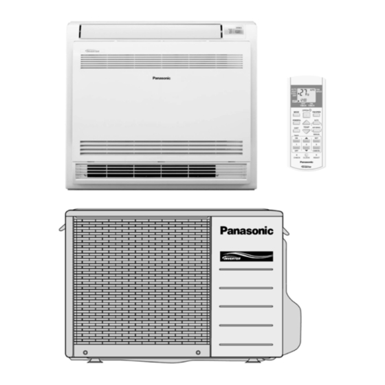
3. Location of Controls and Components Indoor Unit Outdoor Unit Remote Control... -
Page 15: Dimensions
4. Dimensions Outdoor Unit 4.1.1 CU-E9PFE 4.1.2 CU-E12PFE... - Page 16 4.1.3 CU-E18PFE...
-
Page 17: Refrigeration Cycle Diagram
5. Refrigeration Cycle Diagram CU-E9PFE CU-E12PFE... -
Page 18: Cu-E18Pfe
CU-E18PFE... -
Page 19: Block Diagram
6. Block Diagram CU-E9PFE CU-E12PFE... -
Page 20: Cu-E18Pfe
CU-E18PFE... -
Page 21: Wiring Connection Diagram
7. Wiring Connection Diagram Outdoor Unit 7.1.1 CU-E9PFE CU-E12PFE Resistance of Compressor Windings Resistance of Compressor Windings MODEL CU-E9PFE MODEL CU-E12PFE CONNECTION 5RS102XBC21 (Ω) CONNECTION 5RS102XNA21 (Ω) 0.858 1.211 0.858 1.211 0.858 1.211 Note: Resistance at 20°C of ambient temperature. Note: Resistance at 20°C of ambient temperature. - Page 22 7.1.2 CU-E18PFE Resistance of Compressor Windings MODEL CU-E18PFE CONNECTION 5RD132XBA21 (Ω) 1.897 1.907 1.882 Note: Resistance at 20°C of ambient temperature.
-
Page 23: Electronic Circuit Diagram
8. Electronic Circuit Diagram Outdoor Unit 8.1.1 CU-E9PFE CU-E12PFE... - Page 24 8.1.2 CU-E18PFE...
-
Page 25: Printed Circuit Board
9. Printed Circuit Board Outdoor Unit 9.1.1 CU-E9PFE... - Page 26 9.1.2 CU-E12PFE...
- Page 27 9.1.3 CU-E18PFE...
-
Page 28: Installation Instruction
10. Installation Instruction 10.1 Indoor Unit 10.1.1 Selecting the Installation Location Indoor Unit Location for securing the mounting panel. Before choosing the installation site, obtain user approval. Do not install the unit in excessive oil fume area such as kitchen, workshop and etc. There should not be any heat source or steam near the unit. -
Page 29: Installing The Indoor Unit
10.1.2 Selection of Pipe and Heat Insulation Materials When using commercial copper pipes and fittings, observe the following: Insulation material: Polyethylene foam Heat transfer rate: 0.041 to 0.052 W/mK (0.035 to 0.045kcal/mh°C) Refrigerant gas pipe’s surface temperature reaches 110°C max. Choose heat insulation materials that will withstand this temperature. -
Page 30: Drain Piping
10.1.3.1.3 Drain piping Use commercial rigid polyvinyl chloride pipe (general VP-20 pipe, outer diameter 26 mm, inner diameter 20 mm) for the drain pipe. The drain hose (outer diameter 18 mm at connecting end, 220 mm long) is supplied with the indoor unit. Prepare the drain pipe picture below position. - Page 31 Once refrigerant piping and drain piping connections are complete, fill in the gap of the through hole with putty. A gap can lead to condensation on the refrigerant pipe, and drain pipe, and the entry of insects into the pipes. Attach the front panel and front grille in their original positions once all connections are complete.
-
Page 32: Concealed Installation
10.1.3.2.4 Indoor unit installation Remove the front grille. Remove the 7 screws. Remove the upper casing (2 tabs). Remove the side casings (2 tabs on each side). Attach the indoor unit to the wall and secure using screws in 6 locations (M4 x 25L). Use drain pan edge for horizontal projection of the indoor unit. -
Page 33: Connecting The Drain Hose
10.1.3.3.3 Changing upward air flow limit dipswitch Change the upward air flow limit dipswitch (SW2-4) to ON to limit the upward air flow. Remove the front grille. Switch the dipswitch (SW2-4) on the PCB in the electrical equipment box to ON. How to set and use the switch Switch number SW2-4... - Page 34 10.1.5.1 Checking for gas leakage Check for leakage of gas after air purging. 10.1.5.2 Insulating the refrigerant piping Attach the pipe after checking for gas leakage, described above. Cut the insulated portion of the on-site piping, matching it up with the connecting portion. Secure the slit on the auxiliary pipe side with the butt joint on the connection pipe using the tape, making sure there are no gaps.
-
Page 36: Outdoor Unit
10.2 Outdoor Unit 10.2.1 Selecting the Installation Location Before choosing the installation site, obtain user approval. If an awning is built over the unit to prevent direct sunlight or rain, be careful that heat radiation from the condenser is not obstructed. There should not be any animal or plant which could be affected by hot air discharged. -
Page 37: Evacuation Of The Equipment
10.2.3 Connecting the Refrigerant Piping Decide piping length and then cut by using pipe cutter. Remove burrs from cut edge. Make flare after inserting the flare nut (locate at valve) onto the copper pipe. Align center of pipe to valve and then tighten with torque wrench to the specified torque as stated in the table. Do not overtighten, overtightening may cause gas leakage Piping size Torque... -
Page 38: Piping Insulation
Disconnect the charging hose from the vacuum pump and from the service port of the 3-way valve. Tighten the service port caps of the 3-way valve at a torque of 18 N•m with a torque wrench. Remove the valve caps of both of the 2-way valve and 3-way valve. Position both of the valves to “OPEN” using a hexagonal wrench (4 mm). - Page 39 10.2.8 Auto switch operation The following operations can be performed by pressing the “AUTO” switch. AUTO OPERATION MODE The Auto operation will be activated immediately once the Auto Switch is pressed. TEST RUN OPERATION (FOR PUMP DOWN/SERVICING PURPOSE) The Test Run operation will be activated if the Auto Switch is pressed continuously for more than 5 sec.
-
Page 40: Protection Control
11. Protection Control 11.1 Protection Control For All Operations 11.1.1 Restart Control (Time Delay Safety Control) The Compressor will not turn on within 3 minutes from the moment operation stops, although the unit is turned on again by pressing OFF/ON button at remote control within this period. This control is not applicable if the power supply is cut off and on again. - Page 41 11.1.4 Compressor Overheating Prevention Control Instructed frequency for compressor operation will be regulated by compressor discharge temperature. The changes of frequency are as below. If compressor discharge temperature exceeds 107°C, compressor will be stopped, occurs 4 times per 20 minutes, timer LED will be blinking.
-
Page 42: Protection Control For Cooling & Soft Dry Operation
11.2 Protection Control For Cooling & Soft Dry Operation 11.2.1 Outdoor Air Temperature Control The compressor operating frequency is regulated in accordance to the outdoor air temperature as shown in the diagram below. This control will begin 1 minute after the compressor starts. Compressor frequency will adjust base on outdoor air temperature. -
Page 43: Protection Control For Heating Operation
11.2.6 Odor Cut Control To reduce the odor released from the unit. Start Condition AUTO FAN Speed is selected during COOL or DRY operation. During freeze prevention control and timer preliminary operation, this control is not applicable. Control content Depends on compressor conditions: 1. -
Page 44: Disassembly And Assembly Instructions
12. Disassembly and Assembly Instructions WARNING High Voltage is generated in the electrical parts area by the capacitor. Ensure that the capacitor has discharged sufficiently before proceeding with repair work. Failure to heed this caution may result in electric shocks. 12.1 Outdoor Electronic Controller Removal Procedure 12.1.1 CU-E9PFE... - Page 45 12.1.2 CU-E12PFE Caution! When handling electronic controller, be careful of electrostatic discharge. Remove the 5 screws of the Top Panel. Remove the Control Board as follows: Fig. 1 Fig. 4 Remove the 8 screws of the Front Panel. Fig. 2 Fig.
- Page 46 12.1.3 CU-E18PFE Remove the 4 screws of the Top Panel. Remove the Control Board. Fig. 4 Remove the 8 screws of the Electronic Controller. Fig. 1 Remove the 10 screws of the Front Panel. Fig. 5 Fig. 2 Remove the Top Cover of the Electronic Caution! When handling electronic controller, be careful of Controller.
-
Page 47: Technical Data
13. Technical Data 13.1 Operation Characteristics 13.1.1 CS-E9GFEW CU-E9PFE CS-E9GFEW-2 CU-E9PFE Cooling Characteristic [Condition] Indoor temperature: 27/19°C Piping Length: 5m Remote condition: High fan speed, Cool 16°C Comp. Hz: F 16.400 15.900 15.400 14.900 14.400 13.900 Outdoor Air Temperature (°C) 3.000... - Page 48 Piping Length Characteristic [Condition] Indoor temperature: 27/19°C, 35/-°C Remote condition: High fan speed, Cool 16°C Comp. Hz: F 15.600 15.500 15.400 15.300 15.200 15.100 15.000 Piping Length (m) 2.550 2.500 2.450 2.400 2.350 Piping Length (m) 2.630 2.580 2.530 2.480 2.430 2.380 Piping Length (m)
- Page 49 Heating Characteristic [Condition] Indoor temperature: 20/-°C Piping Length: 5m Remote condition: High fan speed, Heat 30°C Comp. Hz: F 41.000 39.000 37.000 35.000 33.000 31.000 29.000 27.000 Outdoor Air Temperature (°C) 4.200 3.700 3.200 2.700 2.200 1.700 Outdoor Air Temperature (°C) 4.000 3.800 3.600...
- Page 50 Piping Length Characteristic [Condition] Indoor temperature: 20/-°C, 7/6°C Remote condition: High fan speed, Heat 30°C Comp. Hz: F 38.400 38.200 38.000 37.800 37.600 37.400 37.200 37.000 Piping Length (m) 3.500 3.400 3.300 3.200 3.100 Piping Length (m) 3.900 3.800 3.700 3.600 3.500 3.400...
- Page 51 13.1.2 CS-E12GFEW CU-E12PFE CS-E12GFEW-2 CU-E12PFE Cooling Characteristic [Condition] Indoor temperature: 27/19°C Piping Length: 5m Remote condition: High fan speed, Cool 16°C Comp. Hz: F 14.300 13.800 13.300 12.800 12.300 11.800 Outdoor Air Temperature (°C) 4.100 3.900 3.700 3.500 3.300 3.100 2.900 Outdoor Air Temperature (°C) 5.400...
- Page 52 Piping Length Characteristic [Condition] Indoor temperature: 27/19°C, 35/-°C Remote condition: High fan speed, Cool 16°C Comp. Hz: F 13.200 13.100 13.000 12.900 12.800 12.700 Piping Length (m) 3.550 3.500 3.450 3.400 3.350 3.300 Piping Length (m) 4.400 4.350 4.300 4.250 4.200 4.150 4.100...
- Page 53 Heating Characteristic [Condition] Indoor temperature: 20/-°C Piping Length: 5m Remote condition: High fan speed, Heat 30°C Comp. Hz: F 44.200 42.200 40.200 38.200 36.200 34.200 32.200 30.200 Outdoor Air Temperature (°C) 5.000 4.500 4.000 3.500 3.000 2.500 2.000 Outdoor Air Temperature (°C) 5.000 4.800 4.600...
- Page 54 Piping Length Characteristic [Condition] Indoor temperature: 20/-°C, 7/6°C Remote condition: High fan speed, Heat 30°C Comp. Hz: F 41.600 41.400 41.200 41.000 40.800 40.600 40.400 40.200 Piping Length (m) 4.100 4.000 3.900 3.800 3.700 3.600 Piping Length (m) 4.800 4.700 4.600 4.500 4.400...
- Page 55 13.1.3 CS-E18GFEW CU-E18PFE Cooling Characteristic [Condition] Indoor temperature: 27/19°C Piping Length: 5m Remote condition: High fan speed, Cool 16°C Comp. Hz: F 12.500 12.300 12.100 11.900 11.700 11.500 11.300 11.100 10.900 Outdoor Air Temperature (°C) 5.600 5.400 5.200 5.000 4.800 4.600 4.400 4.200...
- Page 56 Piping Length Characteristic [Condition] Indoor temperature: 27/19°C, 35/-°C Remote condition: High fan speed, Cool 16°C Comp. Hz: F 11.800 11.700 11.600 11.500 Piping Length (m) 5.100 5.000 4.900 4.800 Piping Length (m) 7.300 7.200 7.100 7.000 6.900 6.800 6.700 6.600 Piping Length (m) 0.840 0.830...
- Page 57 Heating Characteristic [Condition] Indoor temperature: 20/-°C Piping Length: 5m Remote condition: High fan speed, Heat 30°C Comp. Hz: F 46.000 44.000 42.000 40.000 38.000 36.000 34.000 Outdoor Air Temperature (°C) 6.500 6.000 5.500 5.000 4.500 4.000 3.500 Outdoor Air Temperature (°C) 8.200 7.700 7.200...
- Page 58 Piping Length Characteristic [Condition] Indoor temperature: 20/-°C, 7/6°C Remote condition: High fan speed, Heat 30°C Comp. Hz: F 42.800 42.700 42.600 42.500 42.400 Piping Length (m) 5.840 5.820 5.800 5.780 5.760 Piping Length (m) 7.600 7.500 7.400 7.300 7.200 7.100 7.000 6.900 6.800...
-
Page 59: Sensible Capacity Chart
13.2 Sensible Capacity Chart CU-E9PFE 220/230/240V Outdoor Temperature 30 °C 35 °C 40 °C 46 °C Indoor wet bulb 17.0 °C 2.48 1.88 0.51 2.32 1.80 0.55 2.16 1.73 0.58 1.96 1.65 0.63 19.0 °C 2.50 0.56 19.5 °C 2.72 1.97 0.52 2.55... -
Page 60: Exploded View And Replacement Parts List
14. Exploded View and Replacement Parts List 14.1 Outdoor Unit 14.1.1 CU-E9PFE Note The above exploded view is for the purpose of parts disassembly and replacement. The non-numbered parts are not kept as standard service parts. - Page 61 SAFETY REF. NO. PART NAME & DESCRIPTION QTY. CU-E9PFE REMARK CHASSIS COMPLETE CWD50K2073 SOUND PROOF MATERIAL CWG302314 FAN MOTOR BRACKET CWD541089 SCREW - FAN MOTOR BRACKET CWH551217 FAN MOTOR ARS6411AC SCREW - FAN MOTOR MOUNT CWH55252J PROPELLER FAN ASSY CWH03K1010 NUT - PROPELLER FAN CWH56053J COMPRESSOR...
- Page 62 SAFETY REF. NO. PART NAME & DESCRIPTION QTY. CU-E9PFE REMARK OPERATING INSTRUCTION CWF569015 INSTALLATION INSTRUCTION CWF615933 INSTALLATION INSTRUCTION CWF615934 INSTALLATION INSTRUCTION CWF615935 INSTALLATION INSTRUCTION CWF615936 INSTALLATION INSTRUCTION CWF615937 INSTALLATION INSTRUCTION CWF615938 INSTALLATION INSTRUCTION CWF615939 INSTALLATION INSTRUCTION CWF615940 INSTALLATION INSTRUCTION CWF615941 INSTALLATION INSTRUCTION CWF615942 INSTALLATION INSTRUCTION...
- Page 63 14.1.2 CU-E12PFE Note The above exploded view is for the purpose of parts disassembly and replacement. The non-numbered parts are not kept as standard service parts.
- Page 64 SAFETY REF. NO. PART NAME & DESCRIPTION QTY. CU-E12PFE REMARK CHASSIS COMPLETE CWD52K1277 SOUND PROOF MATERIAL CWG302719 FAN MOTOR BRACKET CWD541167 SCREW - FAN MOTOR BRACKET CWH551217 FAN MOTOR ARS6411AC SCREW - FAN MOTOR MOUNT CWH55252J PROPELLER FAN ASSY CWH03K1066 NUT - PROPELLER FAN CWH56053J COMPRESSOR...
- Page 65 SAFETY REF. NO. PART NAME & DESCRIPTION QTY. CU-E12PFE REMARK INSTALLATION INSTRUCTION CWF615933 INSTALLATION INSTRUCTION CWF615934 INSTALLATION INSTRUCTION CWF615935 INSTALLATION INSTRUCTION CWF615936 INSTALLATION INSTRUCTION CWF615937 INSTALLATION INSTRUCTION CWF615938 INSTALLATION INSTRUCTION CWF615939 INSTALLATION INSTRUCTION CWF615940 INSTALLATION INSTRUCTION CWF615941 INSTALLATION INSTRUCTION CWF615942 INSTALLATION INSTRUCTION CWF615943 INSTALLATION INSTRUCTION...
- Page 66 14.1.3 CU-E18PFE Note The above exploded view is for the purpose of parts disassembly and replacement. The non-numbered parts are not kept as standard service parts.
- Page 67 SAFETY REF. NO. PART NAME & DESCRIPTION QTY. CU-E18PFE REMARK CHASSIS COMPLETE CWD52K1261 ANTI - VIBRATION BUSHING CWH50077 COMPRESSOR 5RD132XBA21 NUT - COMPRESSOR MOUNT CWH56000J SOUND PROOF MATERIAL CWG302744 FAN MOTOR BRACKET CWD541153 FAN MOTOR ARW8401AC SCREW - FAN MOTOR BRACKET CWH551217 SCREW - FAN MOTOR MOUNT CWH551106J...
- Page 68 SAFETY REF. NO. PART NAME & DESCRIPTION QTY. CU-E18PFE REMARK INSTALLATION INSTRUCTION CWF615933 INSTALLATION INSTRUCTION CWF615934 INSTALLATION INSTRUCTION CWF615935 INSTALLATION INSTRUCTION CWF615936 INSTALLATION INSTRUCTION CWF615937 INSTALLATION INSTRUCTION CWF615938 INSTALLATION INSTRUCTION CWF615939 INSTALLATION INSTRUCTION CWF615940 INSTALLATION INSTRUCTION CWF615941 INSTALLATION INSTRUCTION CWF615942 INSTALLATION INSTRUCTION CWF615943 INSTALLATION INSTRUCTION...
Need help?
Do you have a question about the CS-E9GFEW and is the answer not in the manual?
Questions and answers