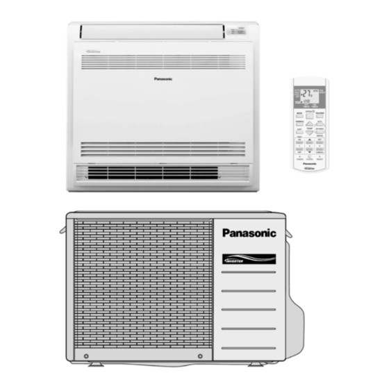
Panasonic CS-E9GFEW Service Manual
Hide thumbs
Also See for CS-E9GFEW:
- Operating instructions manual (80 pages) ,
- Service manual (68 pages) ,
- User manual (8 pages)
Table of Contents
Advertisement
Quick Links
Please file and use this manual together with the Service Manual for Model No. CU-2E15GBE, Order No. MAC0704001A2, Model
No. CU-3E18EBE, Order No. RAC0602011C2, Model No. CU-3E23CBPG, CU-4E27CBPG, Order No.RAC0209005C2.
CONTENTS
1 Safety Precautions----------------------------------------------- 2
2 Specifications ----------------------------------------------------- 4
2.1. Floor Type --------------------------------------------------- 4
2.2. Outdoor Unit: CU-2E15GBE ---------------------------10
2.3. Outdoor Unit: 3E18EBE--------------------------------- 11
4E27CBPG-------------------------------------------------12
3 Features ------------------------------------------------------------16
3.1. Remote Control -------------------------------------------17
3.2. Indoor Unit--------------------------------------------------18
CS-E9GFEW CU-E9GFE
CS-E12GFEW CU-E12GFE
CS-E18GFEW CU-E18GFE
PAGE
3.3. Outdoor Unit----------------------------------------------- 19
4 Location of Controls and Components------------------ 20
4.1. Indoor Unit ------------------------------------------------- 20
4.2. Outdoor Unit----------------------------------------------- 20
4.3. Remote Control------------------------------------------- 20
5 Dimensions ------------------------------------------------------- 21
5.1. Indoor Unit ------------------------------------------------- 21
5.2. Outdoor Unit----------------------------------------------- 22
6 Refrigeration Cycle Diagram -------------------------------- 24
© 2007 Panasonic HA Air-Conditioning (M) Sdn. Bhd.
(11969-T). All rights reserved. Unauthorized copying
and distribution is a violation of law.
Order No. RAC0704001C2
Air Conditioner
PAGE
Advertisement
Table of Contents

Related Manuals for Panasonic CS-E9GFEW


Summary of Contents for Panasonic CS-E9GFEW
-
Page 1: Table Of Contents
3 Features ------------------------------------------------------------16 5.2. Outdoor Unit----------------------------------------------- 22 3.1. Remote Control -------------------------------------------17 6 Refrigeration Cycle Diagram -------------------------------- 24 3.2. Indoor Unit--------------------------------------------------18 © 2007 Panasonic HA Air-Conditioning (M) Sdn. Bhd. (11969-T). All rights reserved. Unauthorized copying and distribution is a violation of law. -
Page 2: Safety Precautions
6.1. CS-E9GFEW CU-E9GFECS-E12GFEW CU- 9.12. Auto Operation Switch --------------------------------- 45 E12GFE ---------------------------------------------------- 24 9.13. Freeze Prevention Control ---------------------------- 45 6.2. CS-E18GFEW CU-E18GFE -------------------------- 25 9.14. Dew Prevention Control-------------------------------- 46 7 Wiring Connection Diagram --------------------------------- 26 9.15. Protection Control Features--------------------------- 46 7.1. - Page 3 For electrical work, follow the local national wiring standard, regulation and the installation instruction. An independent circuit and single outlet must be used. If electrical circuit capacity is not enough or defect found in electrical work, it will cause electrical shock or fire. Use the specified cable and connect tightly for indoor/outdoor connection.
-
Page 4: Specifications
2 Specifications 2.1. Floor Type 2.1.1. CS-E9GFEW CU-E9GFE ITEM UNIT CS-E9GFEW CU-E9GFE 2.50 (0.80 ~ 3.00) Cooling Capacity kCal/h 2,150 (690 ~ 2,580) BTU/h 8,500 (2,700 ~ 10,200) 3.60 (0.80 ~ 5.00) Heating Capacity kCal/h 3,100 (690 ~ 4,300) BTU/h... - Page 5 ITEM UNIT CS-E9GFEW CU-E9GFE Type — Compressor Motor Type — Brushless (4-poles) Rated Output — Type Turbo Fan Propeller Fan Material Motor Type Transistor (8-poles) Induction (6-poles) Input — — Air Circulation Rated Output Fan Speed Lo (Cool / Heat) 620 / 630 —...
- Page 6 2.1.2. CS-E12GFEW CU-E12GFE ITEM UNIT CS-E12GFEW CU-E12GFE 3.50 (0.80 ~ 3.80) Cooling Capacity kCal/h 3,010 (690 ~ 3,270) BTU/h 11,900 (2,700 ~ 13,000) 4.80 (0.80 ~ 6.10) Heating Capacity kCal/h 4,130 (690 ~ 5,240) BTU/h 16,400 (2,700 ~ 20,800) Moisture Removal pt/h (4.2) Phase...
- Page 7 ITEM UNIT CS-E12GFEW CU-E12GFE Type Turbo Fan Propeller Fan Material Motor Type Transistor (8-poles) Induction (6-poles) Input — — Air Circulation Rated Output Fan Speed Lo (Cool / Heat) 640 / 650 — Me (Cool / Heat) 530 / 530 —...
- Page 8 2.1.3. CS-E18GFEW CU-E18GFE ITEM UNIT CS-E18GFEW CU-E18GFE 5.00 (0.90 ~ 5.60) Cooling Capacity kCal/h 4,300 (780 ~ 4,820) BTU/h 17,100 (3,100 ~ 19,100) 5.80 (0.90 ~ 7.10) Heating Capacity kCal/h 4,990 (780 ~ 6,100) BTU/h 19,800 (3,100 ~ 24,200) Moisture Removal pt/h (5.9) Phase...
- Page 9 ITEM UNIT CS-E18GFEW CU-E18GFE Air Circulation Type Turbo Fan Propeller Fan Material Motor Type Transistor (8-poles) Transistor (8-poles) Input — — Rated Output Fan Speed Lo (Cool / Heat) 760 / 860 — Me (Cool / Heat) 660 / 720 —...
-
Page 10: Outdoor Unit: Cu-2E15Gbe
2.2. Outdoor Unit: CU-2E15GBE... -
Page 11: Outdoor Unit: 3E18Ebe
2.3. Outdoor Unit: 3E18EBE... -
Page 12: Outdoor Unit: Cu-3E23Cbpg Cu-4E27Cbpg
2.4. Outdoor Unit: CU-3E23CBPG CU-4E27CBPG... -
Page 16: Features
3 Features • Product - A single OUTDOOR unit enable air conditioning of up to two separate rooms for CU-2E15GBE. - A single OUTDOOR unit enable air conditioning of up to three separate rooms for CU-3E18EBE and CU-3E23CBPG. - A single OUTDOOR unit enable air conditioning of up to four separate rooms for CU-4E27CBPG. Remarks;... -
Page 17: Remote Control
3.1. Remote Control... -
Page 18: Indoor Unit
3.2. Indoor Unit... -
Page 19: Outdoor Unit
3.3. Outdoor Unit... -
Page 20: Location Of Controls And Components
4 Location of Controls and Components 4.1. Indoor Unit 4.2. Outdoor Unit 4.3. Remote Control... -
Page 21: Dimensions
5 Dimensions 5.1. Indoor Unit... -
Page 22: Outdoor Unit
5.2. Outdoor Unit 5.2.1. CU-E9GFE CU-E12GFE... - Page 23 5.2.2. CU-E18GFE...
-
Page 24: Refrigeration Cycle Diagram
6 Refrigeration Cycle Diagram 6.1. CS-E9GFEW CU-E9GFE CS-E12GFEW CU-E12GFE... -
Page 25: Cs-E18Gfew Cu-E18Gfe
6.2. CS-E18GFEW CU-E18GFE... -
Page 26: Wiring Connection Diagram
7 Wiring Connection Diagram 7.1. Indoor Unit... -
Page 27: Outdoor Unit
7.2. Outdoor Unit 7.2.1. CU-E9GFE CU-E12GFE... - Page 28 7.2.2. CU-E18GFE...
-
Page 29: Electronic Circuit Diagram
8 Electronic Circuit Diagram 8.1. Indoor Unit / Remote Controller... - Page 30 Control board (MAIN) Control board (DISPLAY & RECEIVE) Control board (DISPLAY)
-
Page 31: Outdoor Unit
8.2. Outdoor Unit 8.2.1. CU-E9GFE CU-E12GFE... - Page 32 8.2.2. CU-E18GFE...
- Page 33 Control board (OUTDOOR UNIT)
-
Page 34: Operation And Control
9 Operation and Control 9.1. Simultaneous Operation Control (Multi Type Only) 1. Operation modes which can be selected using the remote control unit: Automatic, Cooling, Dry, Heating, Fan operation mode. 2. Types of operations modes which can be performed simultaneously •... -
Page 35: Basic Function
9.2. Basic Function Inverter control, which equipped with a microcomputer in determining the most suitable operating mode as time passes, automatically adjusts output power for maximum comfort always. In order to achieve the suitable operating mode, the microcomputer maintains the set temperature by measuring the temperature of the environment and performing temperature shifting. -
Page 36: Room Temperature Control (Compressor Control)
Table (d): Indoor Air Temperature Shifting 1. Target room temperature shift value (dGetaDst) • To offset the absolute gap between detection temperature with actual room temperature. • The heat exchanger unit’s temperature is different based on operation mode, it becomes the action operation mode value. Actual operation mode Target room temperature offset value (dGetaDst) Cooling... -
Page 37: Automatic Operation
9.3.1. Cooling Operation • Compressor is OFF when Intake Air Temperature - Internal Setting Temperature < -1.5 C. • Compressor is ON after waiting for 3 minutes, if the Intake Air Temperature - Internal Setting Temperature > Compressor OFF point. 9.3.2. - Page 38 Values of T1, T2, and T3 depend on remote control setting temperature, as shown in below table. After the adjustment of T1, T2 and T3 values, the operation mode for that particular environment and remote control setting is judged and performed, based on the above operation mode chart, every *(A) minutes.
-
Page 39: Indoor Fan Motor Operation
• Required rotation speed for fan is set to respond to the remote control setting (10 rpm unit). [Cooling, Dry, Fan] During upper air outlet discharge Remote Control QUIET Tab (rpm) CS-E9GFEW CS-E12GFEW CS-E18GFEW [Cooling, Dry, Fan] During upper and lower air outlets discharge Remote Control... - Page 40 B. Indoor Fan Control i. Indoor fan control operation outline 1. Cooling / Dry Cooling Under different mode standby [Multi type] Stop Forced Operation — Automatic operation mode Min. control judgement Timer OFF shifting operation Automatic operation Powerful Setting +40rpm Manual Quiet Setting +60rpm...
-
Page 41: Airflow Direction Control
Model No. A No. B No. C Powerful Program CS-E9GFEW 1090 1110 1130 CS-E12GFEW 1090 1110 1130 CS-E18GFEW 1210 1230 1250 Normal Program CS-E9GFEW 1050 1070 1090 CS-E12GFEW 1050 1070 1090 CS-E18GFEW 1170 1190 1210 Quiet Program CS-E9GFEW 1030 1050... -
Page 42: Heating Operation
9.6.2. Cooling/Dry Operation AIR SWING; AUTO • When AIR SWING-AUTO of remote control button is pressed, the upper air outlet swings in the range of the upper limit and the lower limit. • When fan motor stop, vertical airflow direction louver does not swing. •... - Page 43 9.6.6. Quiet operation (Cooling Mode/Cooling area of Dry Mode) A. Purpose To provide quiet cooling operation compare to normal operation. B. Control condition a. Quiet operation start condition • When “quiet” button at remote control is pressed. Quiet LED illuminates. b.
-
Page 44: Powerful Mode Operation
9.7. Powerful Mode Operation When the powerful mode is selected, the internal setting temperature will shift to achieve the setting temperature quickly. Single Type: After the startup Powerful, Powerful lamp 20 minutes illumination. Multi Type: At the time of Powerful driving, Powerful lamp illumination. (a) Cooling Operation (b) Dry Operation (c) Heating Operation... -
Page 45: Auto Restart Control
9.10. Auto Restart Control 1. When the power supply is cut off during the operation of air conditioner, the compressor will re-operate within three to four minutes (there are 10 patterns between 2 minutes 58 seconds and 3 minutes 52 seconds to be selected randomly) after power supply resumes. -
Page 46: Dew Prevention Control
9.14. Dew Prevention Control a. Purpose To prevent dew. b. Control start conditions When indoor units are ceiling floor, duct and mini-cassette. c. Control contents Hz control is carried out according to the dew prevention status transmitted from indoor. Control contents Dew prevention status (transmitted indoor) Relative control domain... -
Page 47: Compressor Tank Temperature Rise Protection Control
9.15.1.4. IPM (Power transistor) Prevention Control A. Overheating Prevention Control 1. When the IPM temperature rises to 100 C, compressor operation will stop immediately. 2. Compressor operation restarts after three minutes the temperature decreases to 95 C. B. DC Peak Current Control 1. - Page 48 2. Outdoor total current I Air conditioning: 0.65<=I<1.65. Heating: 0.65<=I<1.65 It is not during deice operation 3. During cooling and dry operation: indoor suction-indoor piping temperature is below 4 C. During heating operation: Indoor piping temperature-indoor suction is under 5 C. Control contents: •...
- Page 49 9.15.2. Protection Control For Cooling & Dry Operation 9.15.2.1. Outdoor Air Temperature Control The compressor operating frequency is regulated in accordance to the outdoor air temperature as shown in the diagram below. This control will begin 1 minute after the compressor starts. 9.15.2.2.
-
Page 50: Protection Control For Heating Operation
3. Control contents - Change a current limit value in a protection location A. (Refer to the clause of total running current control value) 4. Condition resolutive It is canceled when it stops satisfying all of the above-mentioned. 9.15.2.3. Anti-Freezing Control 1. - Page 51 9.15.3.2. Outdoor Air Temperature Control The Max current value is regulated in accordance to the outdoor air temperature as shown in the below figures. 9.15.3.3. Overload Protection Control The compressor operating frequency is regulated in accordance to indoor heat exchanger temperature as shown in below figures.
-
Page 52: Deice Control
9.15.3.4. Deice Control A. Deice operation (Normal Deice Operation) 1. Detection methods Outdoor heat exchanger temperature sensor, timer. 2. Deice operation time chart Notes • During deice operation, as relationship for outdoor piping temperature and time T5, the priority given to the condition which is first fulfilled and shift to the next mode. -
Page 53: Self Diagnosis Display
10 Self Diagnosis Display 10.1. Self Diagnosis Function • Breakdown contents can be verified by Error Code indicated at indoor unit. The Error Code indicator is located inside suction grille. Could be see when suction grille is opened. • The Error Code could be recalled by pressing the 'CHECK' button at remote control with thin stick. -
Page 54: Error Codes Table
10.2. Error Codes Table Diagnosis Abnormality Emergency Note Abnormality / Protection control Primary location to verify display Judgement operation Indoor / outdoor abnormal > 1 min after starting Indoor fan • Internal / external cable communication operation operation only connections •... - Page 55 Diagnosis Abnormality Emergency Note Abnormality / Protection control Primary location to verify display Judgement operation Refrigeration cycle abnormality 2 times occurrence — • No refrigerant within 20 minutes (3-way valve is closed) Outdoor compressor abnormal revolution 4 times occurance — •...
-
Page 56: Installation Instruction
11 Installation Instruction 11.1. Auto switch operation The following operations can be performed by pressing the “AUTO” switch. 1. AUTO OPERATION MODE The Auto operation will be activated immediately once the Auto Switch is pressed. 2. TEST OPERATION (FOR PUMP DOWN/ SERVICING PURPOSE) The Test Run operation will be activated if the Auto... -
Page 57: Indoor Unit
11.3. Indoor Unit 11.3.1. Selecting the Installation Location • Indoor unit Before choosing the installation site, obtain user approval. - There should not be any heat source or steam near the unit. - There should not be any obstacles blocking the air circulation. - A place where air circulation in the room is good. -
Page 58: Installing The Indoor Unit
• Remote controller - Signals may not be transmitted and received correctly when the remote controller is operated while in the holder. Take the remote controller in your hand to operate the unit. - Mount the holder in a location that is not subject to the effects of heat (direct sunlight and stoves, etc.). 11.3.2. - Page 59 To drill a hole in the wall and install a sleeve of piping 1. Insert the piping sleeve to the hole. 2. Fix the bushing to the sleeve. 3. Cut the sleeve until it extrudes about 15 mm from the wall.
- Page 60 • Connecting the Drain Hose See 4. Connecting the Drain Hose Indoor unit installation • Secure using 6 screws for floor installations. (Do not forget to secure to the rear wall.) • For wall installations, secure the mounting plate using 5 screws and the indoor unit using 4 screws. •...
- Page 61 Installation of supplemental plate for attaching indoor unit • The rear of the unit can be fixed with screws at the points shown in the illustration as below. Be sure to install the supplemental plate in accordance with the depth of the inner wall. Caution •...
-
Page 62: Concealed Installation
11.3.3.3. Concealed installation • Only item peculiar to this installation method are given here. See Exposed installation for additional instructions. Preparation • Install the unit according to the instructions below. Failure to do so may cause lead to both cooling and heating failure and the condensation inside the house. -
Page 63: Connecting The Drain Hose
Caution Be sure to turn on the upward air flow limit dipswitch. Failure to do so may cause incomplete cooling/ heating and formation of condensation inside the house. 11.3.4. Connecting the Drain Hose • Insert the supplied drain hose into the socket of the drain pan. Fully insert the drain hose until it adheres to a seal of the socket. - Page 64 Insulating the refrigerant piping • Attach the pipe after checking for gas leakage, described above. 1. Cut the insulated portion of the on-site piping, matching it up with the connecting portion. 2. Secure the slit on the auxiliary pipe side with the butt joint on the connection pipe using the tape, making sure there are no gaps.
-
Page 65: Outdoor Unit
11.4. Outdoor Unit 11.4.1. Selecting the Installation Location Before choosing the installation site, obtain user approval. • If an awning is built over the unit to prevent direct sunlight or rain, be careful that heat radiation from the condenser is not obstructed. -
Page 66: Evacuation Of The Equipment
Flaring the pipe end 1. Please cut using pipe cutter and then remove the burrs. 2. Remove the burrs by using reamer. If burrs is not removed, gas leakage may be caused. Turn the piping end down to avoid the metal powder entering the pipe. 3. -
Page 67: Connecting The Cable
11.4.5. Connecting the Cable (FOR DETAIL REFER TO WIRING DIAGRAM AT UNIT) 1. Remove the control board cover from the unit by loosening the screw. 2. Connecting cable between indoor unit and outdoor unit shall be approved polychloroprene sheathed 4 x 1.5 mm flexible cord, type designation 245 IEC 57 or heavier cord. -
Page 68: Disassembly And Assembly Instructions
12 Disassembly and Assembly Instructions High voltages are generated in the electrical parts area by the capacitor. Ensure that the capacitor has discharged sufficiently before proceeding with repair work. Failure to heed this caution may result in electric shocks. 12.1. Indoor Unit 1. - Page 69 c. Raise up the resin case, remove the shield plate. Fig. 4 d. Remove the connectors which connected to PCB. (6 places) Remove the Pipe Temperature Sensor from the heat exchanger. Fig. 5 e. Remove the Shield plate in the Control Board Casing. Fig.
- Page 70 f. Remove the terminal cables from the PCB from the Terminal Block (black, white, red) Remove the green cable terminal that connected to the ground terminal. Fig. 7 g. Remove the screws (2 locations) at PCB and take out the PCB. Fig.
- Page 71 5. Removal of Evaporator Push the stoppers at left side of evaporator (2 locations) to loosen the evaporator. At the right side of evaporator, push the stoppers to loosen the evaporator and move the evaporator to right side. Fig. 10 6.
-
Page 72: Outdoor Unit
12.2. Outdoor Unit 12.2.1. CU-E9GFE CU-E12GFE 1. Remove the top panel and front panel • Be save to return the wiring to its original position • There are many high voltage components within the heat sink cover so never touch the interior during operation. Wait at least two minutes after power has been turned off. - Page 73 12.2.2. CU-E18GFE...
-
Page 74: Technical Data
13 Technical Data 13.1. Operation Characteristics CS-E9GFEW CU-E9GFE... - Page 78 CS-E12GFEW CU-E12GFE...
- Page 82 CS-E18GFEW CU-E18GFE...
-
Page 86: Sensible Capacity Chart
13.2. Sensible Capacity Chart CS-E9GFEW CU-E9GFE Outdoor Temp. ( C) 230V 30 C 35 C 40 C 46 C D.B. W.B. 17.0 2.48 2.13 0.52 2.32 2.05 0.56 2.16 1.97 0.60 1.96 1.88 0.65 19.0 2.50 0.57 19.5 2.72 2.23 0.53... -
Page 87: Exploded View And Replacement Parts List
14 Exploded View and Replacement Parts List 14.1. Indoor Unit... - Page 88 REF. NO. PART NAME AND DESCRIPTION QTY. CS-E9GFEW CS-E12GFEW CS-E18GFEW REMARKS EVAPORATOR ASS'Y CW1786554 CW1767368 B1-7 FLARE NUT CW1723546 FITTING SPRING / THERMISTOR CW380120 GROUNDING TIP (W/WASHER) CW113783J FLARE NUT CW119848J CW119849J TURBO FAN ASS'Y CW1767414 AIR GUIDE PLATE ASS'Y...
- Page 89 REF. NO. PART NAME AND DESCRIPTION QTY. CS-E9GFEW CS-E12GFEW CS-E18GFEW REMARKS FIXTURE, REF. PIPING CW1768082 REINFORCE PLATE ASS'Y CW1768099 THERMAL INSULATION ASS'Y CW1768107 REMOTE CONTROL CWA75C3096 INSTALLATION PLATE CW1768121 SCREW KIT CW1786965 DRAIN HOSE ASS'Y CW1768138 TAPE CW1786871 THERMISTOR (FOR AIR)
-
Page 90: Cu-E9Gfe Cu-E12Gfe
14.2. CU-E9GFE CU-E12GFE Note: The above exploded view is for the purpose of parts disassembly and replacement. The non-numbered parts are not kept as standard service parts. - Page 91 REF. NO. PART NAME AND DESCRIPTION QTY. CU-E9GFE CU-E12GFE CHASSY ASSY CWD50K2073 ANTI-VIBRATION BUSHING CWH50077 COMPRESSOR 5RS102XBC01 NUT-COMPRESSOR MOUNT CWH56000J SOUND PROOF MATERIAL CWG302293 SOUND PROOF MATERIAL CWG302292 FAN MOTOR BRACKET CWD541030 FAN MOTOR (AC 25W SINGLE) (AC 30W SINGLE) CWA951405J CWA951407J SCREW - FAN MOTOR BRACKET...
-
Page 92: Cu-E18Gfe
14.3. CU-E18GFE Note: The above exploded view is for the purpose of parts disassembly and replacement. The non-numbered parts are not kept as standard service parts. - Page 93 REF. NO. PART NAME AND DESCRIPTION QTY. CU-E18GFE CHASSY ASSY CWD50K2085 ANTI-VIBRATION BUSHING CWH50077 COMPRESSOR 5CS130XAD04 NUT-COMPRESSOR MOUNT CWH56000J SOUND PROOF MATERIAL CWG302302 FAN MOTOR BRACKET CWD541054 FAN MOTOR CWA981166J SCREW - FAN MOTOR BRACKET CWH551198 SCREW - FAN MOTOR MOUNT CWH551106J PROPELLER FAN ASSY CWH03K1016...
- Page 94 REF. NO. PART NAME AND DESCRIPTION QTY. CU-E18GFE SOUND PROOF MATERIAL CWG302300 (Note) • All parts are supplied from PHAAM, Malaysia (Vendor Code: 061). • "O" maked parts are recommended to be kept in stock. [PHAAM] Printed in Malaysia SFYF0703 - 00...
Need help?
Do you have a question about the CS-E9GFEW and is the answer not in the manual?
Questions and answers