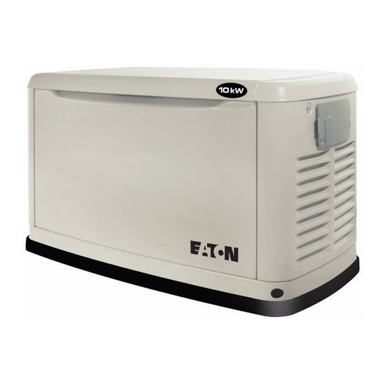
Eaton 8kW Owner's Manual

Eaton 8kW Owner's Manual

Automatic standby generator
Hide thumbs Also See for 8kW:

Advertisement

Owner's Manual
Automatic Standby Generator
n
NOT INTENDED FOR USE IN CRITICAL
LIFE SUPPORT APPLICATIONS.
n
ONLY QUALIFIED ELECTRICIANS OR
CONTRACTORS SHOULD ATTEMPT
INSTALLATION.
n
DEADLY EXHAUST FUMES! OUTDOOR
INSTALLATION ONLY!
This manual should remain with the unit.
Eaton Generator Support 1-800-975-8331
Home Standby Models:
8kW to 20kW
C
LISTED
US

Advertisement

Table of Contents
loading

Summary of Contents for Eaton 8kW

  • Page 1 Owner’s Manual Automatic Standby Generator Home Standby Models: 8kW to 20kW NOT INTENDED FOR USE IN CRITICAL LIFE SUPPORT APPLICATIONS. ONLY QUALIFIED ELECTRICIANS OR CONTRACTORS SHOULD ATTEMPT INSTALLATION. DEADLY EXHAUST FUMES! OUTDOOR LISTED INSTALLATION ONLY! This manual should remain with the unit.
  • Page 2 SERVICE DEALER, please call this number: 1-800-975-8331 or, visit the website at: generators.eaton.com WARNING! California Proposition 65 Engine exhaust and some of its constituents are known to the state of California to cause cancer, birth defects, and other reproductive harm.
  • Page 3: Table Of Contents

    Table of Contents Section 1 — Safety ................1 1.1 —...
  • Page 4 This page intentionally left blank.
  • Page 5: Section 1 - Safety

    Safety Section 1 INTRODUCTION: Thank you for purchasing this compact, high performance, air-cooled, engine-driven stationary automatic standby generator set. Every effort was made to make sure that the information and instructions in this manual were both accurate and current at the time the man- ual was written.
  • Page 6: General Safety

    1.1 — General Safety Study these safety rules carefully before operating or servicing this equipment. Become familiar with this Owner’s Manual and with the unit. The generator can operate safely, efficiently and reliably only if it is properly installed, operated and maintained. Many accidents are caused by failing to follow simple and fundamental rules or precautions.
  • Page 7: Exhaust Hazards

    1.3 — Exhaust Hazards • Generator engine exhaust contains DEADLY carbon monoxide, an odorless, colorless, poisonous gas. Breathing carbon monoxide can cause dizziness, throbbing temples, nausea, muscular twitching, headache, vomiting, weakness, sleepiness, inability to think clearly, fainting, unconsciousness or even death. If any carbon monoxide poisoning symptom is experienced, move into fresh air and immediately seek med- ical attention.
  • Page 8 If this generator is used to power electrical load circuits normally powered by a utility power source, it is required by code to install a transfer switch. The transfer switch must effectively isolate the electrical system from the utility distribution system when the generator is operating (NEC 702). Failure to isolate an electrical system by such means will result in damage to the generator and also may result in injury or death to utility power workers due to backfeed of electrical energy.
  • Page 9: Section 2 - General Information

    BREAKERS EXHAUST ENCLOSURE AIR FILTER FUEL INLET (BACK) FUEL REGULATOR COMPOSITE BASE BATTERY COMPARTMENT OIL FILL CAP OIL FILTER Figure 2-1: GH-410 Engine 8kW Unit CONTROL CONTROL PANEL PANEL DATA LABEL DATA LABEL (SEE SAMPLE) (SEE SAMPLE) CIRCUIT DIPSTICK DIPSTICK...
  • Page 10: Protection Systems

    CONTROL PANEL DATA LABEL (SEE SAMPLE) CIRCUIT DIPSTICK AIR FILTER BREAKERS EXHAUST ENCLOSURE FUEL INLET (BACK) FUEL REGULATOR COMPOSITE BASE BATTERY COMPARTMENT OIL FILTER OIL FILL CAP Figure 2-3: GT-990/GT-999 Engines, 14-20kW Unit 2.2 — Protection Systems The generator may have to run for long periods of time with no operator present to monitor the engine/generator conditions. Therefore, the gen- erator is equipped with a number of systems to automatically shut down the unit to protect it against potentially damaging conditions.
  • Page 11: Emission Information

    2.3 — Emission Information The U.S. Environmental Protection Agency (EPA) requires that this generator comply with exhaust emission standards. This generator is certified to meet the applicable EPA emission levels and is certified for use as a stationary engine for standby power generation. Any other use may be a violation of federal and/or local laws.
  • Page 12: Specifications

    2.4 — Specifications 2.4.1 — Generator Model 20kW 11kW 14kW 17kW Rated Voltage Rated Maximum Load Current 33.3 45.8 58.3 70.8 83.3 (Amps) at 240 Volts (LP)* Main Circuit Breaker 35 Amp 50 Amp 60 Amp 65 Amp 90 Amp Phase Rated AC Frequency 60 Hz...
  • Page 13: Accessories

    The specification sheet for your generator was included in the documentation provided with the unit at the time of purchase. For additional cop- ies, consult your local Authorized Service Dealer for your specific generator model. 2.4.3 — Fuel Requirements The engine has been fitted with a dual fuel carburetion system. The unit will run on natural gas or LP gas (vapor), but it has been factory set to run on natural gas.
  • Page 14 This page intentionally left blank. Automatic Standby Generator Owner’s Manual...
  • Page 15: Section 3 - Operation

    Operation Section 3 3.1 — Control Panel Interface The control panel on this unit is intended to only be operated by qualified service personnel. The Control panel interface is located under the lid of the enclosure. Before attempting to lift the lid of the enclosure, verify that both left and right side locks are unlocked.
  • Page 16: Using The Auto/Off/Manual Buttons

    Figure 3-2: Generator Control Panel 3.2 — Using the Auto/Off/Manual Buttons Button Description of Operation Auto Selecting this button activates fully automatic system operation. It also allows the unit to automatically star t and exercise the engine every seven days with the setting of the exercise timer (see the Setting the Exercise Timer section). This button shuts down the engine and also prevents automatic operation of the unit.
  • Page 17 Figure 3-3: Navigation Menu Automatic Standby Generator Owner’s Manual...
  • Page 18: Automatic Transfer Operation

    The system will control the cyclic cranking as follows: • 8kW unit - 5 cranking cycles as follows: 15 second crank, seven (7) second rest, followed by four (4) additional cycles of seven (7) second cranks followed by seven (7) second rests.
  • Page 19: Turning The Generator Off When Operating Under Load

    3.5 — Turning the Generator Off When Operating Under Load NOTE: Important! To turn the generator off during prolonged utility outages to perform maintenance or conserve fuel, follow these simple, but important steps: To turn the generator OFF (while running in AUTO and online): 1.
  • Page 20: Side Compartment

    3.6.2— Transfer Back to Utility Power Source When utility power has been restored, transfer back to utility source and shut down the generator. To manually transfer back to utility power and shut down the generator: 1. Set the Main Circuit Breaker (Generator Disconnect) to its OFF (OPEN) position. 2.
  • Page 21: Alarm Response Procedures

    3.7.3— 120V GFCI Outlet/15 Amp Breaker (17 & 20 kW Only) All units are equipped with an external 15 amp, 120 volt GFCI convenience outlet located in the top corner of the compartment. When the generator is running, in the absence of utility power, this outlet may also be used to power items outside the home such as lights or power tools.
  • Page 22 This page intentionally left blank. Automatic Standby Generator Owner’s Manual...
  • Page 23: Section 4 - Maintenance

    Maintenance Section 4 NOTE: Proper maintenance and proper and safe operation is crucial to the life of the generator. Genuine Generac parts MUST be used to ensure warranty coverage. NOTE: Since most maintenance alerts will occur at the same time (most have two year intervals), only one will appear on the Control Panel display at any one time.
  • Page 24: Checking Engine Oil Level

    4.2.1— Maintenance Log Battery inspection and charge check (recommended every 6 months for the life of the battery) Dates Performed: Oil, oil filter, air filter and spark plug replacement (recommended every 200 hours or 2 years, whichever occurs first) Dates Performed: Valve Adjustment (recommended after the first 6 months after installation or 500 hours of operation, whichever occurs first, and every 500 hours thereafter) Dates Performed:...
  • Page 25 4.3.1— Engine Oil Recommendations To maintain the warranty, genuine Generac replacement parts MUST be used, including Generac oil kits (which include an oil and air filter). Gen- erac oil kits can be obtained through an Authorized Dealer or purchased on-line. To purchase on-line, access the maintenance kits page through www.generac.com or directly at shop.generac.com.
  • Page 26: Changing The Engine Air Cleaner

    With the generator shut down, lift the lid and remove the front panel. Remove the cover clips and air cleaner cover (11-20kW), or disengage the wire clip and open the air cleaner access door (8kW). Pull out the old air filter and discard.
  • Page 27: Valve Lash Adjustment

    4.6 — Valve Lash Adjustment After the first six (6) months or 500 hours of operation, check the valve clearance. Adjust if necessary. Important: Please contact the Dealer for service assistance. This is a very important step to ensure longest life for the engine. To check valve clearance: •...
  • Page 28: Battery Maintenance

    Rocker Pivot Ball Stud Jam Nut Valve Stem Figure 4-4: Valve Clearance Adjustment 4.7 — Battery Maintenance The battery should be regularly inspected per the Service Schedule: With the generator shut down, lift the lid and remove the front panel. Inspect the battery posts and cables for tightness and corrosion.
  • Page 29: Attention After Submersion

    Do not open or mutilate the battery. Released electrolyte has been known to be harmful to the skin and eyes, and to be toxic. The electrolyte is a dilute sulfuric acid that is harmful to the skin and eyes. It is electrically conduc- tive and corrosive.
  • Page 30 11. Remove the battery and store it in a cool, dry room on a wooden board. Never store the battery on any concrete or earthen floor. 12. Clean and wipe down the entire generator. 4.10.2— Return to Service To return the unit to service after storage: Verify that utility power is turned off.
  • Page 31: Section 5 - Troubleshooting

    Troubleshooting Section 5 Problem Cause Correction The engine will not crank. Fuse blown. Correct short circuit condition by replacing 7.5 Amp fuse in generator control panel. Loose, corroded or defective Tighten, clean or replace battery cables. as necessary.* Defective starter contact. *See #2.
  • Page 32 This page intentionally left blank. Automatic Standby Generator Owner’s Manual...
  • Page 33: Section 6 - Quick Reference Guide

    Quick Reference Guide Section 6 Things to Problem Solution Active Alarm Check Unit running in AUTO but no power Check MLCB. Contact servicing dealer if GREEN Check MLCB. NONE in house. MLCB is in the ON position. Check the Check ventilation around the intake, HIGH Unit shuts down during operation.
  • Page 34 Things to Problem Solution Active Alarm Check Check the Unit will not start in AUTO with utility STEPPER LEDs/Screen Contact servicing dealer. loss. OVERCURRENT for alarms. Check the Unit will not start in AUTO with utility LEDs/Screen MISWIRE Contact servicing dealer. loss.
  • Page 36 Part No. 0J9943Y10 Rev. D 08/13/2013 Printed in USA Generac Power Systems, Inc. © Generac Power Systems, Inc. All rights reserved S45 W29290 Hwy. 59 Specifications are subject to change without notice. Waukesha, WI 53189 No reproduction allowed in any form without prior written 1-888-GENERAC (1-888-436-3722) consent from Generac Power Systems, Inc.

This manual is also suitable for:

11kw20kw14kw17kw

Table of Contents