
Related Manuals for Eaton RPM-3U


Summary of Contents for Eaton RPM-3U
- Page 1 Eaton Rack Power Module 24–96A: 208Y/120V, 400Y/230V User's Guide p/n: 164201675 Revision 02...
- Page 2 Eaton reserves the right to change specifications without prior notice. . All other trademarks are property of their respective companies. ©Copyright 2007-2022 Eaton, Raleigh, NC, USA. All rights reserved. No part of this document may be reproduced in any way without the...
- Page 3 Eaton, Powerware, and BladeUPS are registered trademarks of Eaton Corporation or its subsidiaries and affiliates. Phillips and Pozidriv are registered trademarks of Phillips Screw Company. ECopyright 2008–2010 Eaton Corporation, Raleigh, NC, USA. All rights reserved. No part of this document may be reproduced in any way without the express written approval of Eaton Corporation.
-
Page 5: Table Of Contents
6 6 W W a a r r r r a a n n t t y y ............................................................2 2 7 7 Eaton Rack Power Module... - Page 6 Table of Contents Eaton Rack Power Module 164201675—Rev 02...
-
Page 7: 1 I I N N T T R R O O D D U U C C T T I I O O N
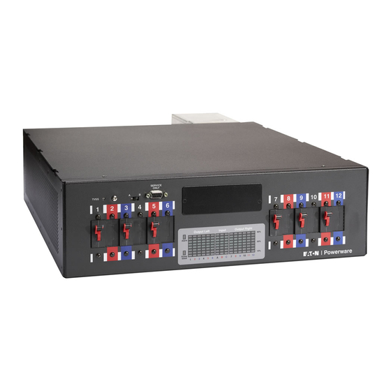
The RPM-3U/3Ui also improves load balancing, reducing nuisance overload alarms from the UPS. • Indicator LEDs that show when incoming power is available to the RPM-3U/3Ui and when an alarm is present. • Columns of LEDs labeled to match the output breaker poles and the input lines. Each column displays a reading of load status. - Page 8 Consignes de sécurité • To reduce the risk of fire or electric shock, install this RPM-3U/3Ui in a temperature and humidity controlled, indoor environment, free of conductive contaminants. Ambient temperature must not exceed 30°C (86°F). Do not operate near water or excessive humidity (95% maximum).
- Page 9 GUARDE ESTAS INSTRUCCIONES Este manual contiene instrucciones importantes que debe seguir durante la instalacion y el funcionamiento de la RPM-3U/3Ui. Por favor, lea todas las instrucciones antes de poner en funcionamiento el equipo y guarde este manual para referencia en el futuro.
- Page 10 30°C. No trabaje cerca del agua o con humedad excesiva (95% maximo). • Para cumplir con los estandares internacionales y las normas de instalacion, la totalidad de los equipos conectados a la salida de este RPM-3U/3Ui no debe tener una intensidad de perdida a tierra superior a los 3,5 miliamperios. •...
-
Page 11: 2 I I N N S S T T A A L L L L A A T T I I O O N
C C h h e e c c k k i i n n g g t t h h e e A A c c c c e e s s s s o o r r y y K K i i t t Verify that the following items are included with the RPM-3U/3Ui. -
Page 12: Cable Tray Installation (Optional)
Follow these instructions only if you are installing an optional cable tray on an RPM-3U/ 3Ui that will be installed in a rack. If you are mounting the RPM-3U/3Ui on a wall, install the cable tray as part of the wallmount installation. See the following section, “... -
Page 13: Wallmount Installation
Install two customer-supplied mounting fasteners for the top keyhole slots into the wall (do not tighten). Place the RPM-3U/3Ui on the wall, and adjust the placement so that the fasteners mounted on the wall move into the small ends of the keyhole slots. -
Page 14: Rack Installation
Access to the front, rear, and both sides of the rack is required to install the RPM-3U/3Ui in the rack. To install the RPM-3U/3Ui in a rack: Align the front mounting brackets with the screw holes on the sides of the RPM-3U/3Ui as shown in Figure Secure the brackets with the supplied four M4 flat-head screws. -
Page 15: 4 S S P P E E C C I I F F I I C C A A T T I I O O N N S
RPM-3U/3Ui as shown in Figure Verify that the brackets are seated firmly, then tighten the wing nuts. The RPM-3U/3Ui is now secured in the rack. Figure 5. Attaching the RPM-3U/3Ui to the Rack (Hardwired Unit Shown) -
Page 16: Plug-Receptacle Installation
“Table 25 ”. Make provision for any required cord retention or strain relief. For each receptacle to be monitored, turn its circuit breaker on the RPM-3U/3Ui front panel to the ON ( | ) position. NOTE If power to the RPM-3U/3Ui is interrupted, check each circuit breaker and reset if necessary. -
Page 17: Hardwired Installation
Verify that the RPM-3U/3Ui is properly installed in the rack or wallmount brackets and that each circuit breaker on the RPM-3U/3Ui front panel is in the OFF (O) position. The Power indicator should be off. If your rack has conductors for grounding or bonding of ungrounded metal parts, connect the ground cable (not included) to the ground bonding screw on the RPM-3U/3Ui rear panel. - Page 18 The RPM-3U/3Ui receptacles are protected separately by each circuit breaker on the front panel. NOTE 2 Confirm that the equipment connected to the RPM-3U/3Ui does not exceed the RPM- 3U/3Ui's capacity. See “Specifications” for the maximum rating for each receptacle. Eaton Rack Power Module...
-
Page 19: Advanced Metering Installation (Optional)
“Table 25”. 12. Make provision for any required cord retention or strain relief. 13. For each receptacle to be monitored, turn its circuit breaker on the RPM-3U/3Ui front panel to the ON ( | ) position. NOTE If power to the RPM-3U/3Ui is interrupted, check each circuit breaker and reset if necessary. - Page 20 Advanced Metering Installation (Optional) Eaton Rack Power Module 164201675—Rev 02...
-
Page 21: Introduction
RPM-3U/3Ui. Each output plate contains a set of distribution receptacles. The two output plates may be of the same receptacle type or different types. -
Page 22: Service Only Port And Switches
The Output Left LEDs display the load capacity of breaker poles 1–6; the Output Right LEDs display breaker poles 7–12. The Input LEDs display the input current (phases A, B, C for RPM-3U units, or L1, L2, L3 for RPM- 3Ui units). - Page 23 LEDs to indicate load status. Breaker metering is normalized: the RPM-3U/3Ui scales the display readings based on the type of breaker (15A, 20A, 30A) used on the output and the ratings on the input. If a mix of breaker amperages are connected, then all are normalized to the highest rating.
- Page 24 LED Display Eaton Rack Power Module 164201675—Rev 02...
- Page 25 S S p p e e c c i i f f i i c c a a t t i i o o n n s s This section provides the following specifications for the Rack Power Module (RPM-3U/3Ui): •...
- Page 26 400Y/230V only: CE Mark, CB Report, IEC/EN 60950-1, GOST Seismic Uniform Building Code (UBC) for Zone 4 Earthquake Table 8. Electrical Input Nominal Voltage (Range) RPM-3U: 208V (176–260V) RPM-3Ui: 400V (300–460V) Nominal Frequency (Range) 50/60 Hz (45–65 Hz) Input Conductor Configuration 3 wire + N + Gnd...
- Page 27 Table 16. Output Plate Receptacle Type L14-30R Receptacle Voltage Number of Receptacles Receptacle Phases Power Connection 208 Vac Phase to Neutral Receptacles per Breaker Breaker Rating Number of Breakers 3 two-pole breakers 30A / 5,000 AIC Eaton Rack Power Module 164201675—Rev 02...
- Page 28 Table 22. Output Plate Receptacle Type IEC 320-C13 (400Y/230V) Receptacle Voltage Number of Receptacles Receptacle Phases Power Connection 230 Vac Phase to Neutral Receptacles per Breaker Breaker Rating Number of Breakers 6 single-pole breakers 10A / 5,000 AIC Eaton Rack Power Module 164201675—Rev 02...
- Page 29 Table 24. Output Plate Receptacle Type IEC 320-C19 (400Y/230V) Receptacle Voltage Number of Receptacles Receptacle Phases Power Connection 230 Vac Phase to Neutral Receptacles per Breaker Breaker Rating Number of Breakers 6 single-pole breakers 16A / 5,000 AIC Eaton Rack Power Module 164201675—Rev 02...
- Page 30 Specifications Figure 13. Output Receptacle Types 5-15R L14-20R IEC 320-C13 (208Y/120V) 5-20R L14-30R IEC 320-C13 (400Y/230V) L6-15R L15-20R IEC 320-C19 (208Y/120V) L6-20R L15-30R IEC 320-C19 (400Y/230V) L6-30R Eaton Rack Power Module 164201675—Rev 02...
-
Page 31: Typical Alarms And Conditions
S S e e r r v v i i c c e e a a n n d d S S u u p p p p o o r r t t If you have any questions or problems with the RPM-3U/3Ui, call your Local Distributor or the Help Desk at... -
Page 32: Service And Support
Service and Support Eaton Rack Power Module 164201675—Rev 02... - Page 33 C C h h a a p p t t e e r r 6 6 W W a a r r r r a a n n t t y y 6 6 . . 1 1 W W a a r r r r a a n n t t y y Limited Factory Warranty Eaton Rack Power Module 164201675—Rev 02...
- Page 34 16420167502 164201675 02...
Need help?
Do you have a question about the RPM-3U and is the answer not in the manual?
Questions and answers