Table of Contents

Related Manuals for Eaton DV2-A10B


Summary of Contents for Eaton DV2-A10B
- Page 1 Data-Voice-Video 3G Power Solutions Installation and Operation Guide (UL-Listed Models) Issue: IPN 997-00012-82B Issue Date: May 2011 Eaton Corporation Telecommunications Power Solutions www.eaton.com/telecompower DCinfo@eaton.com...
- Page 2 The information contained in this literature is subject to change without notice. Subject to the right to use its equipment, Eaton Corporation does not convey any right, title or interest in its intellectual property, including, without limitation, its patents, copyrights and know-how.
-
Page 3: About This Guide
For details refer to the system controller operation handbook listed under Related Information on page i. Installation and configuration of Eaton SiteSure and CellSure modules. For details, refer to the relevant guide listed under Related Information on page i. -
Page 4: For Further Information And Technical Assistance
Data-Voice-Video 3G Power Solutions (UL-Listed Models) For Further Information and Technical Assistance For further information and technical assistance see Worldwide Support on page 85. Copyright © 2011 Eaton Corporation. All Rights Reserved. IPN 997-00012-82B May 2011... -
Page 5: Table Of Contents
Battery Types .......................... 28 Installing the Batteries ......................28 Install the Batteries ........................29 Battery Cable Links for Additional Battery Racks (if required) ..........31 Installation procedure ........................31 Copyright © 2011 Eaton Corporation. All Rights Reserved. IPN 997-00012-82B May 2011... - Page 6 System Controller Connector Pin-outs ................69 I/O Board (IOBGP-00, -01) Connector Pin-outs ..............71 Appendix D System Wiring Diagrams Appendix E Checklists Equipment Incident Report Worldwide Support Index Copyright © 2011 Eaton Corporation. All Rights Reserved. IPN 997-00012-82B May 2011...
-
Page 7: Overview
Chapter 1 General Description General Description Overview Topic Page DC Power Systems Rectifiers SC200 System Controller Input/Output Board Other Features Copyright © 2011 Eaton Corporation. All Rights Reserved. IPN 997-00012-82B May 2011... -
Page 8: Dc Power Systems
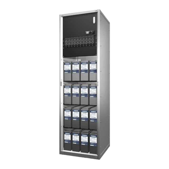
4U space for optional second DCM2000 20-way dc circuit Information on page i.) breaker distribution module. See details on page 7. 3U space for other equipment (DV2-A10B models only). A full-height security door (not shown) is supplied with all ... -
Page 9: Rectifiers
Ethernet interface, Web server, and SNMP agent. Alarm notifications may be by SNMP traps, SMS text messaging, dial-out to PowerManagerII remote monitoring software, or relay contact closures. Copyright © 2011 Eaton Corporation. All Rights Reserved. IPN 997-00012-82B May 2011... -
Page 10: Compatible Software
DCTools Configuration Software. Latest version is available free from www.powerquality.eaton.com/downloads. PowerManagerII Remote Control and Monitoring Software. Contact your Eaton dc product supplier for further information (see Worldwide Support on page 85). Recommended web browsers: Microsoft Internet Explorer 8 (IE6 is compatible but with ... - Page 11 Load Fuse Fail, Battery Fuse Fail, AC Distribution Fan Fail, AC Distribution MOV Fail) - YH3 See Troubleshooting on page for details of I/O board LED signals. Copyright © 2011 Eaton Corporation. All Rights Reserved. IPN 997-00012-82B May 2011...
-
Page 12: Connections
Connection to dc common bus connections Connection to dc live bus For connector pin-outs see details on page 71. For input and output specifications see details on page 65. Copyright © 2011 Eaton Corporation. All Rights Reserved. IPN 997-00012-82B May 2011... -
Page 13: Other Features
This dc distribution module can have either a single or dual feed from the DCM2000 in the dc power system cabinet. For details of how to fit the DCM2000 dc distribution module , see details on page 25. Copyright © 2011 Eaton Corporation. All Rights Reserved. IPN 997-00012-82B May 2011... -
Page 14: Battery Mid-Point Monitoring Description
A rear extension cabinet is available for bottom cable entry. See Parts List on page 62. For details of how to fit the rear extension cabinet, refer to Fit the Rear Extension Cabinet on page 15. Copyright © 2011 Eaton Corporation. All Rights Reserved. IPN 997-00012-82B May 2011... -
Page 15: Preparation
Chapter 2 Preparation Preparation Overview Topic Page Warnings Inspecting the Equipment and Reporting Damage Copyright © 2011 Eaton Corporation. All Rights Reserved. IPN 997-00012-82B May 2011... -
Page 16: Warnings
Do not exceed the maximum load currents stated in the Specifications on page 65. Battery Current The short circuit current capability of the battery circuit connected to the battery input terminals must not exceed 5,000A. Copyright © 2011 Eaton Corporation. All Rights Reserved. IPN 997-00012-82B May 2011... - Page 17 Eaton. This includes disassembly and/or servicing of any modules. For further information on Servicing contact your local Eaton dc product supplier, or refer to the contact details on page 85. Copyright © 2011 Eaton Corporation. All Rights Reserved.
-
Page 18: Inspecting The Equipment And Reporting Damage
EMC Compliance This Eaton product ("the equipment") has been tested and found to comply with the limits for a Class A digital device, pursuant to part 15 of the Federal Communications Commission (FCC) Rules. These limits are designed to provide reasonable protection against harmful interference when the equipment is operated in a commercial environment. -
Page 19: Positioning Cabinets
Chapter 3 Positioning Cabinets Positioning Cabinets Overview Topic Page Preparation Fixing Cabinets Fit the Rear Extension Cabinet (if required) Copyright © 2011 Eaton Corporation. All Rights Reserved. IPN 997-00012-82B May 2011... -
Page 20: Preparation
Mark fixing holes in base of cabinet with permanent marker. Remove cabinet. Drill all marked holes. De-burr all holes. Place cabinets back in position. Fix cabinet using appropriate floor anchors to secure the cabinets. Copyright © 2011 Eaton Corporation. All Rights Reserved. IPN 997-00012-82B May 2011... -
Page 21: Cabinet Footprint
Step 1 - Cut floor holes for cables Use the bottom panel from the rear extension Drill/cut holes for the cables. cabinet kit as a template to mark the floor. Copyright © 2011 Eaton Corporation. All Rights Reserved. IPN 997-00012-82B May 2011... - Page 22 Step 3 - Fit the rear extension cabinet Assemble the rear extension cabinet. Fit the rear panel when all cables are installed. Fit to the rear of the DV2-3G. Procedure complete Copyright © 2011 Eaton Corporation. All Rights Reserved. IPN 997-00012-82B May 2011...
-
Page 23: Overview
Topic Page DC Installation Practices Connecting the Telecom Earth Cable Fit or Remove Low Voltage Disconnects Load Cables and Circuit Breakers Fit DCM2000 in Battery Cabinet (if required) Copyright © 2011 Eaton Corporation. All Rights Reserved. IPN 997-00012-82B May 2011... -
Page 24: Dc Installation Practices
Use the size and type of cable and crimp lug indicated in the following table. Tighten both bolts to 18.7 - 21.9Nm (166 - 194 inch-pounds). DV2-3G cabinet. Telecom earth cable. Copyright © 2011 Eaton Corporation. All Rights Reserved. IPN 997-00012-82B May 2011... -
Page 25: Fit Or Remove Low Voltage Disconnects
Contactor bus retaining nuts (2 x M10). Contactor bus retaining bolts (2 x M10). Link bar (in place of contactor). Contactor mounting screws and isolators (4 x M4). Copyright © 2011 Eaton Corporation. All Rights Reserved. IPN 997-00012-82B May 2011... - Page 26 Fit the link bar and tighten the two M10 bolts and two M10 nuts to 18.7 - 21.9Nm (166 - 194 inch-pounds) Replace the access panel. Copyright © 2011 Eaton Corporation. All Rights Reserved. IPN 997-00012-82B May 2011...
- Page 27 Undo the two bolts and remove the contactor and bus work. Fit the link bar and tighten the two M10 bolts to 18.7 - 21.9Nm (166 - 194 inch- pounds). Replace the access panel. Copyright © 2011 Eaton Corporation. All Rights Reserved. IPN 997-00012-82B May 2011...
-
Page 28: Load Cables And Circuit Breakers
Step 1 - Access circuit breakers Open the hinged front cover. Switch off all circuit breakers. Undo and remove the circuit breaker cover. If necessary, remove cabinet side panels for rear/top access. Copyright © 2011 Eaton Corporation. All Rights Reserved. IPN 997-00012-82B May 2011... - Page 29 (Note 3) 5A, 10A, 15A YAV10-2TC14 Y8MRB-1 25A, 30A YA8CL-2TC14 YAV6CL-2TC14 60A, 70A Y1MRTC YAV4CL-2TC14 100A, 120A 150A YAV25L-2TC38 Y81KFT, Y81KFTMBH, 200A YAV28L-2NT38 PAT81KFTI8V 250A 250 kcmil YA31L-2TC38 M29-11 Copyright © 2011 Eaton Corporation. All Rights Reserved. IPN 997-00012-82B May 2011...
- Page 30 Fit blank covers over any unused circuit breaker positions. Leave the circuit breakers in the off position and close the hinged front cover until ready to start the dc power system. Procedure complete Copyright © 2011 Eaton Corporation. All Rights Reserved. IPN 997-00012-82B May 2011...
-
Page 31: Fit Dcm2000 In Battery Cabinet (If Required)
Use the M10 nuts and bolts provided. Tighten to 18.7 - 21.9Nm (166 - 194 inch- pounds). DCM2000 mounted in extension battery cabinet (top view). Rack common bar. Common link bar assemblies (two required). Copyright © 2011 Eaton Corporation. All Rights Reserved. IPN 997-00012-82B May 2011... - Page 32 Priority load feed terminated on priority load cabinet (rear view). bar. Distribution link bar. Non-priority load feed terminated on non-priority load bar. Single feed terminated on link bar. Procedure complete Copyright © 2011 Eaton Corporation. All Rights Reserved. IPN 997-00012-82B May 2011...
-
Page 33: Overview
Chapter 5 Battery Installation Battery Installation Overview Topic Page Battery Types Installing the Batteries Copyright © 2011 Eaton Corporation. All Rights Reserved. IPN 997-00012-82B May 2011... -
Page 34: Battery Types
Report any damage or other battery related problems immediately to the battery supplier. Do not remove the factory-fitted transit insulation covers from the batteries until access to the battery terminals is required. Copyright © 2011 Eaton Corporation. All Rights Reserved. IPN 997-00012-82B May 2011... -
Page 35: Install The Batteries
48V batteries use one shelf per battery string. 24V batteries use one shelf for two battery strings. Use suitable lifting equipment and follow all applicable health and safety regulations. Copyright © 2011 Eaton Corporation. All Rights Reserved. IPN 997-00012-82B May 2011... - Page 36 Otherwise, cover the unconnected live cable(s) with at least two layers of insulation tape to prevent accidental contact with the cabinet chassis. Step 7 - Secure batteries Secure the batteries with the clips and straps provided. Copyright © 2011 Eaton Corporation. All Rights Reserved. IPN 997-00012-82B May 2011...
-
Page 37: Battery Cable Links For Additional Battery Racks (If Required)
In multiple rack systems use cable links between adjacent racks to interconnect the busbars in the battery rack(s) and the rectifier rack. Use the Eaton cables listed in Spare Parts on page 62, or use the following cable and crimp lugs: Conductor:... - Page 38 Step 6 - Repeat for other battery rack(s) (if required) If required, repeat the process to connect the busbars of any other battery rack(s) to the adjacent battery rack. Procedure complete Copyright © 2011 Eaton Corporation. All Rights Reserved. IPN 997-00012-82B May 2011...
-
Page 39: Ac Cables
Chapter 6 AC Cables AC Cables Overview Topic Page Input Transient Protection Connecting to the AC Supply Connecting the Output to Earth Copyright © 2011 Eaton Corporation. All Rights Reserved. IPN 997-00012-82B May 2011... -
Page 40: Input Transient Protection
Data-Voice-Video 3G Power Solutions (UL-Listed Models) Input Transient Protection To prevent damage to Eaton Data-Voice-Video 3G Power Solutions from lightning and transient over-voltages, structural lightning protection and transient protection must be installed at each site. Transient protection will also protect against other sources of transients, such as: Circuit or grid switching by the power company ... - Page 41 2kA. Tertiary Transient Protection Eaton rectifiers are fitted with low-level transient protection. This is designed to protect the rectifiers from voltage spikes generated during operation of the upstream transient protection system. Do not install rectifiers without adequate upstream surge protection.
- Page 42 Spark gap (neutral-earth) Main switchboard AC sub-switchboard Switchboard earth/ground busbar Fuses Secondary transient protection Rectifiers Primary transient protection (refer to text for rating) Copyright © 2011 Eaton Corporation. All Rights Reserved. IPN 997-00012-82B May 2011...
-
Page 43: Connecting To The Ac Supply
Only use a three-phase () ac source that is referenced to earth, or has a protection system in place to prevent the phase-earth voltage exceeding the rating of the rectifier. Copyright © 2011 Eaton Corporation. All Rights Reserved. IPN 997-00012-82B... - Page 44 Tighten the terminals to 6Nm (53 lb.-in). Eaton recommends that you strip the insulation back approximately 7mm (¼ inch) and crimp a ferrule over the bare conductor ends. For each of the conductors, ensure that the ferrule fits over all the strands of wire.
- Page 45 Protective earth bonding connections to cabinet frame, dc common bar and rectifier magazine chassis. RM1: Rectifier Magazine 1 P1, P4: Rectifiers 1-3 RM2: Rectifier Magazine 2 P2, P5: Rectifiers 4-6 (DV2-A20B models only) P3, P6: Rectifiers 7-10 Copyright © 2011 Eaton Corporation. All Rights Reserved. IPN 997-00012-82B May 2011...
-
Page 46: Connecting The Output To Earth
Factory fitted ac-dc earth link If your installation uses a mesh earth, then Eaton recommends that this factory fitted ac-dc earth link is retained. No further action is then required (ignore Step 3). However, if your policy is not to bond the ac and communications earth, then go to Step 3. - Page 47 < 1.5pF Capacitance A larger transient earth clamp with a high kA rating must be used if the potential severity of a lightning strike is high. Procedure complete Copyright © 2011 Eaton Corporation. All Rights Reserved. IPN 997-00012-82B May 2011...
- Page 48 Data-Voice-Video 3G Power Solutions (UL-Listed Models) Copyright © 2011 Eaton Corporation. All Rights Reserved. IPN 997-00012-82B May 2011...
-
Page 49: Overview
Task 2 - Pre-Power-Up Checklist Task 3 - Applying AC Power Task 4 - Configure the dc power system Task 5 - Apply DC Power to Battery and Load Start-Up Completed Copyright © 2011 Eaton Corporation. All Rights Reserved. IPN 997-00012-82B May 2011... -
Page 50: Start-Up Tasks
Check the rectifier's rear connector is correctly aligned with the shelf connector, or damage may occur. Tighten the retaining screw to 1.5Nm (13.3 inch-pounds). This will locate the rectifier in its rear connector. Copyright © 2011 Eaton Corporation. All Rights Reserved. IPN 997-00012-82B May 2011... -
Page 51: Task 2 - Pre-Power-Up Checklist
The SC200 system controller will turn on (green Power On LED is on) when dc power is available from the rectifier(s). During start-up of the SC200 system controller, the yellow alarm LED on the rectifier(s) will flash until rectifier registration is completed. Copyright © 2011 Eaton Corporation. All Rights Reserved. IPN 997-00012-82B May 2011... -
Page 52: Task 4 - Configure The Dc Power System
If the configuration file is not fully customized for the site then check the following settings and change if necessary. It is important that these settings are correct before progressing further. Copyright © 2011 Eaton Corporation. All Rights Reserved. IPN 997-00012-82B... -
Page 53: Task 5 - Apply Dc Power To Battery And Load
Close the battery circuit breaker(s). Check the Battery Fuse Fail alarm clears. Check the battery current. The actual value depends on the state of charge of the batteries. Copyright © 2011 Eaton Corporation. All Rights Reserved. IPN 997-00012-82B May 2011... -
Page 54: Start-Up Completed
System Operation to customize the system configuration settings, and Communications to setup the remote communications options. For information on alarms, or operation problems see Maintenance on page 49. Copyright © 2011 Eaton Corporation. All Rights Reserved. IPN 997-00012-82B May 2011... -
Page 55: Maintenance
Eaton. This includes disassembly and/or servicing of any modules. For further information on Servicing contact your local Eaton dc product supplier, or refer to the contact details on page 85. Topic Page... -
Page 56: Troubleshooting
Check rectifier comms bus wiring. If second rectifier registers, then first rectifier is faulty and must be returned for service. Copyright © 2011 Eaton Corporation. All Rights Reserved. IPN 997-00012-82B May 2011... - Page 57 Install additional rectifiers. and rectifier yellow LEDs capacity. are on (rectifiers are in Battery is recharging after ac Check battery has recharged within current limit). supply failure. expected time. Copyright © 2011 Eaton Corporation. All Rights Reserved. IPN 997-00012-82B May 2011...
- Page 58 (Power LED is on). Check that the LVD control and power cables are connected. See Connections on page 6. Check the connections from the battery bus to the LVD. Copyright © 2011 Eaton Corporation. All Rights Reserved. IPN 997-00012-82B May 2011...
- Page 59 Contactor is disconnected. Check the control and dc power cables are connected. See details on page 6. All other SC200 problems. See Troubleshooting in the SC200 Operation Handbook. Copyright © 2011 Eaton Corporation. All Rights Reserved. IPN 997-00012-82B May 2011...
-
Page 60: Replacing Or Adding A Rectifier
Procedure complete Installing a Replacement Rectifier Step 1 - Remove rectifier blank panel (if fitted) Step 2 - Align the rectifier with the guides Copyright © 2011 Eaton Corporation. All Rights Reserved. IPN 997-00012-82B May 2011... -
Page 61: Replacing Or Adding A Circuit Breaker
contact your Eaton dc power system supplier to obtain a master configuration file to suit the dc power system. This file will have to be customized for the site. - Page 62 DCTools/Web to change the configuration settings to the correct values (provided the system controller is set for the correct nominal system voltage). Copyright © 2011 Eaton Corporation. All Rights Reserved. IPN 997-00012-82B May 2011...
- Page 63 Repeat for other LVD(s) if fitted. Remove the LVD bridge cable if fitted. Procedure Complete Return the faulty system controller with a completed Equipment Incident Report on page 83. Copyright © 2011 Eaton Corporation. All Rights Reserved. IPN 997-00012-82B May 2011...
-
Page 64: Replacing The Input/Output Board
Some alarms will clear. The Missing Hardware and LVD alarms (if LVDs are fitted) will still be present. A New Hardware alarm will appear because of the I/O board mapping change. Press any key to silence the alarm. Copyright © 2011 Eaton Corporation. All Rights Reserved. IPN 997-00012-82B May 2011... -
Page 65: Battery Mid-Point Monitoring (String Fail) Alarm
Press any button on the SC200 to silence the alarm. Connect to the SC200 using DCTools/Web. Go to Batteries > Mid-point Monitoring. Click + to expand the Mid-point Monitoring table to identify which battery string has failed. Copyright © 2011 Eaton Corporation. All Rights Reserved. IPN 997-00012-82B May 2011... -
Page 66: Battery Disposal And Recycling
Please remember that the owner is responsible and liable to ensure those EPA guidelines or equivalent local regulations are followed. For assistance contact your local hazardous waste center or Worldwide Support on page 85. Copyright © 2011 Eaton Corporation. All Rights Reserved. IPN 997-00012-82B May 2011... -
Page 67: Appendix A Equipment And Tools
USB port and USB A/B cable (RadioShack 55010997, Jaycar WC7700 or similar) DCTools software (download from www.powerquality.eaton.com/downloads). Test load (to suit maximum output of dc power system) Labeling tool and labels Clamp-on ammeter Copyright © 2011 Eaton Corporation. All Rights Reserved. IPN 997-00012-82B May 2011... -
Page 68: Spare Parts
Eaton CLBBU150-100 (2 required) (fitted). cables are 1m/39" long. Second dc distribution module (mounts in Eaton DCM2000-11X and Eaton BUSCOM-LINK1 optional extension battery cabinet) and common link bar kit Copyright © 2011 Eaton Corporation. All Rights Reserved. IPN 997-00012-82B May 2011... -
Page 69: Parts For Dcm2000 Circuit Breaker Distributions
Circuit breaker, 100A AM1R-B39-AJ-07-D-DU-52-100-251 307-910066-81A Circuit breaker, 200A AM1P-B39-LJ-07-D-AU-52-200-251 307-920086-81A The battery circuit breakers provide an alarm signal if the circuit breaker is electrically tripped or switched off. Copyright © 2011 Eaton Corporation. All Rights Reserved. IPN 997-00012-82B May 2011... -
Page 70: Purchasing Information
Torque is based on 60% of yield stress of the material. Yield for the purposes of this chart is 240MPa. Tolerance range is 60 - 70 % of yield. When a bolt and nut is torqued use a spanner to prevent rotation. Copyright © 2011 Eaton Corporation. All Rights Reserved. IPN 997-00012-82B May 2011... - Page 71 See circuit breaker details on page 63. Low Voltage Disconnects (LVD) Battery disconnect: 600A @ 48V Low-priority load disconnect: 300A @ 48V Battery Shelf circuit breakers 48V: 200A, 2-pole 24V: 100A, 1-pole Copyright © 2011 Eaton Corporation. All Rights Reserved. IPN 997-00012-82B May 2011...
- Page 72 DV2-A10B: 160kg [353 lb] typical DV2-A20B: 170kg [375 lb] typical DV2-EBC4 battery rack: 150kg [331 lb] typical Rear extension cabinet 24kg [53 lb] Rectifier module 1.7kg [3.7 lb] Copyright © 2011 Eaton Corporation. All Rights Reserved. IPN 997-00012-82B May 2011...
- Page 73 Number of Current Sense Inputs 3 (one used for internal battery current shunt) Range –50 to +50mV Resolution <50µV Accuracy ±0.5% at 25°C [77°F], ±1% over rated temperature range Connector RJ45 Copyright © 2011 Eaton Corporation. All Rights Reserved. IPN 997-00012-82B May 2011...
- Page 74 (IE6 is compatible but with reduced performance), Mozilla Firefox 3.0. External modem options Type: PSTN or GSM Operation: Dial in/Dial out on alarm* * Can operate as a backup for Ethernet communications. Copyright © 2011 Eaton Corporation. All Rights Reserved. IPN 997-00012-82B May 2011...
-
Page 75: Appendix C Connector Pin-Outs
RJ45 RXP System +24/48V (System bus voltage) Communications +24/48V (System bus voltage) RS485-A RS485-B USB B USB Serial Interface VCC (+5 V dc) Data - Data + Ground Copyright © 2011 Eaton Corporation. All Rights Reserved. IPN 997-00012-82B May 2011... - Page 76 Data-Voice-Video 3G Power Solutions (UL-Listed Models) RS232 D9M and RJ45 connector pin-outs RJ45 plug pin-outs Copyright © 2011 Eaton Corporation. All Rights Reserved. IPN 997-00012-82B May 2011...
-
Page 77: I/O Board (Iobgp-00, -01) Connector Pin-Outs
Controller reference (Live) Controller sense (Com) XH12A Battery Mid-point String 1 Mid-point Monitoring sense inputs String 2 Mid-point String 3 Mid-point String 4 Mid-point XH15A Digital inputs D1-D3 D1 input Copyright © 2011 Eaton Corporation. All Rights Reserved. IPN 997-00012-82B May 2011... - Page 78 DC power system digital Load Fuse Fail inputs Battery Fuse Fail +12V out AC Distribution Fan Fail AC Distribution MOV Fail 0V out (system live - protected) System common - protected Copyright © 2011 Eaton Corporation. All Rights Reserved. IPN 997-00012-82B May 2011...
- Page 79 * Digital Output 6 is also used as the Monitor Fail alarm relay. It will de-energize if the I/O board loses power or loses communication with the SC200. RJ45 connector pin-outs RJ45 plug pin-outs Copyright © 2011 Eaton Corporation. All Rights Reserved. IPN 997-00012-82B May 2011...
- Page 80 Data-Voice-Video 3G Power Solutions (UL-Listed Models) Copyright © 2011 Eaton Corporation. All Rights Reserved. IPN 997-00012-82B May 2011...
-
Page 81: Appendix D System Wiring Diagrams
Appendix D System Wiring Diagrams System Wiring Diagrams Drawing Number Issue Title 3709087 Battery Cabinet DV2-EBC4-00101 3709088 Wiring Diagram DV2-A20B-32121 48V (+ Earth) System Copyright © 2011 Eaton Corporation. All Rights Reserved. IPN 997-00012-82B May 2011... - Page 82 Data-Voice-Video 3G Power Solutions (UL-Listed Models) Copyright © 2011 Eaton Corporation. All Rights Reserved. IPN 997-00012-82B May 2011...
- Page 83 System Wiring Diagrams Copyright © 2011 Eaton Corporation. All Rights Reserved. IPN 997-00012-82B May 2011...
- Page 84 Data-Voice-Video 3G Power Solutions (UL-Listed Models) Copyright © 2011 Eaton Corporation. All Rights Reserved. IPN 997-00012-82B May 2011...
-
Page 85: Appendix E Checklists
Configuration Printout folder. If the supervisory module’s configuration is incorrect, you can download the correct configuration, which is available from your Eaton dc product representative or make any necessary changes via supervisory module front panel or DCTools. - Page 86 Check mounting of rack and battery stand is to plans and specifications Check clearances around the installed equipment are to plan Check earth (ground) and insulation visually and with meters Batteries (if supplied by your Eaton dc product representative) Battery capacity check Supervisory Module Configuration as in Configuration Printout (or as modified at customer’s request)
- Page 87 Operators and supervisors to obtain overview of documentation Decide location of documentation — logbook, Configuration Printout, and so on. Formal Acceptance Signed acceptance sent to your Eaton dc product representative Starting up records filed Note in logbook and/or Configuration Printout...
- Page 88 Data-Voice-Video 3G Power Solutions (UL-Listed Models) Copyright © 2011 Eaton Corporation. All Rights Reserved. IPN 997-00012-82B May 2011...
-
Page 89: Equipment Incident Report
Please enter as much information as you can. Send the completed form, together with the item for repair to your nearest authorized service agent. NOTE: Only one fault to be recorded per form. For further information contact your local Eaton dc product supplier or Eaton (see contact details on page 85). Or email: CustomerServiceNZ@eaton.com... - Page 90 ______________________________________________________________________________________ ______________________________________________________________________________________ ______________________________________________________________________________________ ______________________________________________________________________________________ ______________________________________________________________________________________ ______________________________________________________________________________________ ______________________________________________________________________________________ ______________________________________________________________________________________ ______________________________________________________________________________________ ______________________________________________________________________________________ ______________________________________________________________________________________ ______________________________________________________________________________________ ______________________________________________________________________________________ ______________________________________________________________________________________ ______________________________________________________________________________________ ______________________________________________________________________________________ ______________________________________________________________________________________ ______________________________________________________________________________________ ______________________________________________________________________________________ ______________________________________________________________________________________ ______________________________________________________________________________________ ______________________________________________________________________________________ ______________________________________________________________________________________ ______________________________________________________________________________________ ______________________________________________________________________________________ ______________________________________________________________________________________ SG/03 ISS06 Copyright © 2011 Eaton Corporation. All Rights Reserved. IPN 997-00012-82B May 2011...
-
Page 91: Worldwide Support
Worldwide Support For product information and a complete listing of worldwide sales offices, visit Eaton's website at: www.eaton.com/telecompower or email: DCinfo@eaton.com For technical support contact either your local Eaton dc product representative, the closest office from the following list, telephone (+64) 3 343-7448, or email CustomerServiceNZ@eaton.com... - Page 92 Data-Voice-Video 3G Power Solutions (UL-Listed Models) Copyright © 2011 Eaton Corporation. All Rights Reserved. IPN 997-00012-82B May 2011...
-
Page 93: Index
Communications Options • 7 Description • 4 Connector • 3, 6 Digital Inputs • 67 DCTools • 4, 7, 61 I/O Board Mapping • 55, 58 GSM Modem Communications • 7 Copyright © 2011 Eaton Corporation. All Rights Reserved. IPN 997-00012-82B May 2011... - Page 94 Reverse Polarity • 47 Software Versions • 4 PowerManagerII • 4 Specifications • 65 Problems • See Troubleshooting String Fail Alarm • 8, 53, 59 PSTN Modem Communications • 7 Copyright © 2011 Eaton Corporation. All Rights Reserved. IPN 997-00012-82B May 2011...
- Page 95 Problems • See Troubleshooting Voltage (Bus) • See Bus Voltage Sense Voltage Control Bus Voltage Sense • 4 Voltage Feed Module • 6 Browsers (recommended) • 4 Web Server • 7 Copyright © 2011 Eaton Corporation. All Rights Reserved. IPN 997-00012-82B May 2011...
Need help?
Do you have a question about the DV2-A10B and is the answer not in the manual?
Questions and answers