
Related Manuals for LevelOne GTL-2691


Summary of Contents for LevelOne GTL-2691
-
Page 1: Installation Guide
GTL-2691 20GE + 4GE Combo SFP+2 10GE XFP Module slot L3 SNMP Stackable Switch Installation Guide version 1.0... - Page 3 N S T A L L A T I O N U I D E GTL-2691 LAYER ANAGED TACKABLE WITCH Layer 3 Gigabit Ethernet Switch with 20 GE Ports, 4 GE Combo SFP Ports and 2 10G Slots Level 1 GTL-2691...
-
Page 5: Japan Vcci Class A
Compliances and Safety Warnings FCC - Class A This equipment has been tested and found to comply with the limits for a Class A digital device, pursuant to part 15 of the FCC Rules. These limits are designed to provide reasonable protection against harmful interference when the equipment is operated in a commercial environment. - Page 6 CE Mark Declaration of Conformance for EMI and Safety (EEC) This information technology equipment complies with the requirements of the Council Directive 89/336/EEC on the Approximation of the laws of the Member States relating to Electromagnetic Compatibility and 73/23/EEC for electrical equipment used within certain voltage limits and the Amendment Directive 93/68/EEC.
-
Page 7: Safety Compliance
Safety Compliance Warning: Fiber Optic Port Safety When using a fiber optic port, never look at the transmit laser while it is powered on. Also, never look directly at the fiber TX port and fiber cable CLASS I LASER DEVICE ends when they are powered on. - Page 8 Important! Before making connections, make sure you have the correct cord set. Check it (read the label on the cable) against the following: Power Cord Set U.S.A. and Canada The cord set must be UL-approved and CSA certified. The minimum specifications for the flexible cord are: - No.
- Page 9 France et Pérou uniquement: Ce groupe ne peut pas être alimenté par un dispositif à impédance à la terre. Si vos alimentations sont du type impédance à la terre, ce groupe doit être alimenté par une tension de 230 V (2 P+T) par le biais d’un transformateur d’isolement à rapport 1:1, avec un point secondaire de connexion portant l’appellation Neutre et avec raccordement direct à...
-
Page 10: Warnings And Cautionary Messages
Stromkabel . Dies muss von dem Land, in dem es benutzt wird geprüft werden: Schweiz Dieser Stromstecker muß die SEV/ASE 1011Bestimmungen ein- halten. Europe Das Netzkabel muß vom Typ HO3VVF3GO.75 (Mindestanforderung) sein und die Aufschrift <HAR> oder <BASEC> tragen. Der Netzstecker muß die Norm CEE 7/7 erfüllen (”SCHUKO”). Warnings and Cautionary Messages Warning: This product does not contain any serviceable user parts. - Page 11 Documentation All printed documentation for this product uses biodegradable paper that originates from sustained and managed forests. The inks used in the printing process are non-toxic.
-
Page 12: About This Guide
About This Guide Purpose This guide details the hardware features of this device, including the physical and performance-related characteristics, and how to install it. Audience The guide is intended for use by network administrators who are responsible for installing and setting up network equipment; consequently, it assumes a basic working knowledge of LANs (Local Area Networks). -
Page 13: Table Of Contents
Contents Chapter 1: Introduction Overview Switch Architecture Network Management Options Description of Hardware 10/100/1000BASE-T Ports SFP Slots 10 Gigabit Ethernet Module Slots Stacking Ports Port and System Status LEDs Optional Redundant Power Supply Power Supply Sockets Optional Media Extender Modules Extender Module LEDs Features and Benefits Connectivity... - Page 14 Contents Desktop or Shelf Mounting Installing an Optional Module into the Switch Installing an Optional SFP Transceiver Connecting Switches in a Stack Stacking Topologies Connecting to a Power Source Connecting to the Console Port Wiring Map for Serial Cable Chapter 4: Making Network Connections Connecting Network Devices Twisted-Pair Devices Cabling Guidelines...
- Page 15 Contents Cable Testing for Category 6 and 6a Cable Adjusting Existing Cabling for 1000BASE-T and 10GBASE-T Fiber Standards Appendix C: Specifications Physical Characteristics Switch Features Management Features Standards Compliances Extender Modules 10GBASE Extender Module (XFP) 10GBASE Extender Module (SFP+) Glossary Index...
- Page 16 Tables Table 1-1 Port Status LEDs Table 1-2 System Status LEDs Table 1-3 Supported XFP Transceivers Table 1-4 Supported SFP Transceivers Table 1-5 Module LEDs Table 3-1 Serial Cable Wiring Table 4-1 Maximum 10GBASE-T Gigabit Ethernet Cable Length Table 4-2 Maximum 10GBASE-SR 10 Gigabit Ethernet Cable Length Table 4-3 Maximum 10GBASE-LR 10 Gigabit Ethernet Cable Length...
- Page 17 Figures Figure 1-1 Front Panel Figure 1-2 Rear Panel Figure 1-3 Port LEDs Figure 1-4 System LEDs Figure 1-5 Power Supply Sockets Figure 1-6 Single-Port 10GBASE Module (XFP) Figure 1-7 Single-Port 10GBASE-T Module (SFP Plus) Figure 2-1 Collapsed Backbone Figure 2-2 Network Aggregation Plan Figure 2-3 Remote Connections with Fiber Cable...
- Page 18 Figures...
-
Page 19: Chapter 1: Introduction
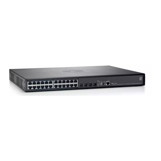
Link Select Module Diag Module Diag Stack Link Stack ID 10/100/1000 Mbps RJ-45 Ports SFP Slots Stack ID Figure 1-1 Front Panel If an SFP transceiver is plugged in, the corresponding RJ-45 port is disabled for ports 21-24 on GTL-2691. -
Page 20: Switch Architecture
(out-of-band), or you can manage the switch through a network connection (in-band) using Telnet, the on-board web agent, or SNMP-based network management software. For a detailed description of GTL-2691’s advanced features, refer to the Gigabit Ethernet Switch Management Guide. -
Page 21: Description Of Hardware
Description of Hardware Description of Hardware 10/100/1000BASE-T Ports The switch contains 20 RJ-45 ports plus four RJ-45 combo ports (shared with SFP slots) that operate at 10 Mbps or 100 Mbps, half or full duplex, or at 1000 Mbps, full duplex. -
Page 22: Table 1-1 Port Status Leds
Introduction Port Status LEDs Figure 1-3 Port LEDs Table 1-1 Port Status LEDs Condition Status Link/ On/Flashing Amber Port has a valid link at 10 or 100 Mbps. Flashing indicates activity. Activity/ On/Flashing Green Port has a valid link at 1000 Mbps. Flashing indicates activity. Speed The link is down. -
Page 23: Optional Redundant Power Supply
Description of Hardware Table 1-2 System Status LEDs (Continued) Condition Status Stack Master Green Switch is the Master unit of the stack. State may include topology discovery, IP assignment, or normal operations. Flashing Green Switch is the Master unit of the stack, system is initializing. Amber Switch is operating as a Slave unit in the stack. -
Page 24: Optional Media Extender Modules
Introduction Optional Media Extender Modules 10GBASE XFP Module MDU-0162 Figure 1-6 Single-Port 10GBASE Module (XFP) The module’s XFP slot supports standard 10 Gigabit Ethernet (10G) XFP transceivers. The 10GBASE transceivers operate at 10 Gbps full duplex with support for flow control. Table 1-3 Supported XFP Transceivers Media Standard Part Number Maximum Distance... -
Page 25: Extender Module Leds
Category 5e, 6, 6a or 7 twisted-pair cable. Performance • Transparent bridging. • Aggregate duplex bandwidth of up to 88 Gbps for the GTL-2691. • Switching table with a total of 16K MAC address entries and 2K IPv4 address entries or 1K IPv6 address entries... -
Page 26: Management
Introduction • Provides store-and-forward switching for intra-VLAN traffic, and IP routing for inter-VLAN traffic. • Supports wire-speed switching at layer 2, and wire-speed routing at layer 3. • Broadcast storm control. Management • “At-a-glance” LEDs for easy troubleshooting • Network management agent: - Manages switch (or entire stack) in-band or out-of-band - Supports console, Telnet, SSH, SNMP v1/v2c/v3, RMON (4 groups) and web-based interface... -
Page 27: Chapter 2: Network Planning
Chapter 2: Network Planning Introduction to Switching A network switch allows simultaneous transmission of multiple packets via non-crossbar switching. This means that it can partition a network more efficiently than bridges or routers. The switch have, therefore, been recognized as one of the most important building blocks for today’s networking technology. -
Page 28: Application Examples
Network Planning Application Examples The Gigabit Ethernet Switch is not only designed to segment your network, but also to provide a wide range of options in setting up network connections and linking VLANs or IP subnets. Some typical applications are described below. Collapsed Backbone The Gigabit Ethernet Switch is an excellent choice for mixed Ethernet, Fast Ethernet, and Gigabit Ethernet installations where significant growth is expected in... -
Page 29: Network Aggregation Plan
Application Examples Network Aggregation Plan With 24 parallel bridging ports (i.e., 24 distinct collision domains), a Gigabit switch stack can collapse a complex network down into a single efficient bridged node, increasing overall bandwidth and throughput. In the figure below, the 10/100/1000BASE-T ports in a stack of 24-port Gigabit Ethernet switches are providing 1000 Mbps connectivity through stackable switches. -
Page 30: Remote Connections With Fiber Cable
Network Planning Remote Connections with Fiber Cable Fiber optic technology allows for longer cabling than any other media type. A 1000BASE-SX (MMF) link can connect to a site up to 550 meters away, a 1000BASE-LX (SMF) link up to 5 km, and a 1000BASE-LH link up to 70 km. This allows a switch stack to serve as a collapsed backbone, providing direct connectivity for a widespread LAN. -
Page 31: Making Vlan Connections
Application Examples Making VLAN Connections The switch support VLANs which can be used to organize any group of network nodes into separate broadcast domains. VLANs confine broadcast traffic to the originating group, and can eliminate broadcast storms in large networks. This provides a more secure and cleaner network environment. -
Page 32: Using Layer 3 Routing
Network Planning Using Layer 3 Routing VLANs can significantly enhance network performance and security. However, if you use conventional routers to interconnect VLANs, you can lose most of your performance advantage. The Gigabit Ethernet Switch is routing switch that provide wire-speed routing, which allows you to eliminate your conventional IP routers, except for a router to handle non-IP protocols and a gateway router linked to the WAN. -
Page 33: Application Notes
Application Notes Application Notes Full-duplex operation only applies to point-to-point access (such as when a switch is attached to a workstation, server or another switch). When the switch is connected to a hub, both devices must operate in half-duplex mode. For network applications that require routing between dissimilar network types, you can attach these switches directly to a multi-protocol router. - Page 34 Network Planning...
-
Page 35: Chapter 3: Installing The Switch
Chapter 3: Installing the Switch Selecting a Site The switch can be mounted in a standard 19-inch equipment rack or on a flat surface. Be sure to follow the guidelines below when choosing a location. • The site should: - be at the center of all the devices you want to link and near a power outlet. - be able to maintain its temperature within 0 to 50 °C (32 to 122 °F) and its humidity within 5% to 95%, non-condensing - provide adequate space (approximately five centimeters or two inches) on all... -
Page 36: Equipment Checklist
Then, before beginning the installation, be sure you have all other necessary installation equipment. Package Contents • GTL-2691 • Four adhesive foot pads • Bracket Mounting Kit containing two brackets and eight screws for attaching the brackets to the switch •... -
Page 37: Mounting
Mounting Mounting A switch unit can be mounted in a standard 19-inch equipment rack or on a desktop or shelf. Mounting instructions for each type of site follow. Rack Mounting Before rack mounting the switch, pay particular attention to the following factors: •... -
Page 38: Desktop Or Shelf Mounting
Installing the Switch Mount the device in the rack, using four rack-mounting screws (not provided). Figure 3-3 Installing the Switch in a Rack If installing a single switch only, turn to "Connecting to a Power Source" at the end of this chapter. If installing multiple switches, mount them in the rack, one below the other, in any order. -
Page 39: Installing An Optional Module Into The Switch
Installing an Optional Module into the Switch are at least two inches of space on all sides for proper air flow. If installing a single switch only, go to "Connecting to a Power Source" at the end of this chapter. If installing multiple switches, attach four adhesive feet to each one. -
Page 40: Installing An Optional Sfp Transceiver
Installing the Switch Installing an Optional SFP Transceiver Figure 3-6 Inserting an SFP Transceiver into a Slot The switch supports 1000BASE-SX and 1000BASE-LX, and 1000BASE-LH SFP-compatible transceivers. To install an SFP transceiver, do the following: Consider network and cabling requirements to select an appropriate SFP transceiver type. -
Page 41: Connecting Switches In A Stack
Connecting Switches in a Stack Connecting Switches in a Stack Figure 3-7 shows how the stack cables are connected between switches in a stack. Each stacking connection is a 48 Gbps full-duplex high-speed serial link using proprietary stacking cables. The switch supports a line- and ring-topology stacking configuration, or can be used stand alone. -
Page 42: Stacking Topologies
Installing the Switch Select the Master unit in the stack by pressing the Master button in on only one of the switches. Only one switch in the stack can operate as the Master, all other units operate in slave mode. If more than one switch in the stack is selected as Master, or if no switches are selected, the system will select the unit with the lowest MAC address as the Master. -
Page 43: Connecting To The Console Port
Connecting to the Console Port Check the front-panel LEDs as the device is powered on to be sure the Power LED is on. If not, check that the power cable is correctly plugged in. If you have purchased a Redundant Power Supply, connect it to the switch and to an AC power source now, following the instructions included with the package. - Page 44 Installing the Switch 3-10...
-
Page 45: Chapter 4: Making Network Connections
Chapter 4: Making Network Connections Connecting Network Devices This switch is designed to interconnect multiple segments (or collision domains). It can be connected to network cards in PCs and servers, as well as to hubs, switches or routers. It may also be connected to devices using optional XFP or SFP transceivers. -
Page 46: Connecting To Pcs, Servers, Hubs And Switches
Making Network Connections Connecting to PCs, Servers, Hubs and Switches Attach one end of a twisted-pair cable segment to the device’s RJ-45 connector. Figure 4-1 Making Twisted-Pair Connections If the device is a PC card and the switch is in the wiring closet, attach the other end of the cable segment to a modular wall outlet that is connected to the wiring closet. -
Page 47: Fiber Optic Sfp Devices
Fiber Optic SFP Devices Equipment Rack (side view) Network Switch M o d u l e D i a g S t a c k I D w it c h 10 /10 0 M o d u l e D i a g 6 7 2 4 L 3 R P S... -
Page 48: 10 Gbps Fiber Optic Connections
Making Network Connections Connect one end of the cable to the LC port on the switch and the other end to the LC port on the other device. Since LC connectors are keyed, the cable can be attached in only one orientation. Figure 4-3 Making Connections to SFP Transceivers As a connection is made, check the Link LED on the switch corresponding to the port to be sure that the connection is valid. -
Page 49: Figure 4-4 Connecting To An Xfp Transceiver
10 Gbps Fiber Optic Connections Check that the fiber terminators are clean. You can clean the cable plugs by wiping them gently with a clean tissue or cotton ball moistened with a little ethanol. Dirty fiber terminators on fiber cables will impair the quality of the light transmitted through the cable and lead to degraded performance on the port. -
Page 50: Connectivity Rules
Making Network Connections Connectivity Rules When adding hubs (repeaters) to your network, please follow the connectivity rules listed in the manuals for these products. However, note that because switches break up the path for connected devices into separate collision domains, you should not include the switch or connected cabling in your calculations for cascade length involving other devices. -
Page 51: 10 Gbps Ethernet Collision Domain
Connectivity Rules 10 Gbps Ethernet Collision Domain Table 4-1 Maximum 10GBASE-T Gigabit Ethernet Cable Length Cable Type Maximum Cable Length Connector Category 5e 100-ohm UTP 45 m (147 ft) RJ-45 Category 6 100-ohm UTP 55 m (180 ft) RJ-45 Category 6a 100-ohm UTP 100 m (328 ft) RJ-45 Category 7 100-ohm STP... -
Page 52: 1000 Mbps Gigabit Ethernet Collision Domain
Making Network Connections 1000 Mbps Gigabit Ethernet Collision Domain Table 4-5 Maximum 1000BASE-T Gigabit Ethernet Cable Length Cable Type Maximum Cable Length Connector Category 5, 5e, 6 100-ohm UTP or STP 100 m (328 ft) RJ-45 Table 4-6 Maximum 1000BASE-SX Gigabit Ethernet Cable Length Fiber Size Fiber Bandwidth Maximum Cable Length... -
Page 53: Cable Labeling And Connection Records
Cable Labeling and Connection Records Cable Labeling and Connection Records When planning a network installation, it is essential to label the opposing ends of cables and to record where each cable is connected. Doing so will enable you to easily locate inter-connected devices, isolate faults and change your topology without need for unnecessary time consumption. - Page 54 Making Network Connections 4-10...
-
Page 55: Appendix A: Troubleshooting
Appendix A: Troubleshooting Diagnosing Switch Indicators Table A-1 Troubleshooting Chart Symptom Action Power LED is Off • Check connections between the switch, the power cord, and the wall outlet. • Contact your dealer for assistance. Power LED is Amber • Internal power supply has failed. Contact your local dealer for assistance. -
Page 56: Power And Cooling Problems
Troubleshooting Power and Cooling Problems If the power indicator does not turn on when the power cord is plugged in, you may have a problem with the power outlet, power cord, or internal power supply. However, if the unit powers off after running for a while, check for loose power connections, power losses or surges at the power outlet, and verify that the fans on the unit are unobstructed and running prior to shutdown. -
Page 57: Stack Troubleshooting
Stack Troubleshooting Stack Troubleshooting If a stack fails to initialize or function, first check the following items: • Check that all stacking cables are properly connected. • Check if any stacking cables appear damaged. • Check that only one Stack Master button is pressed in. •... - Page 58 Troubleshooting...
-
Page 59: Appendix B: Cables
Appendix B: Cables Twisted-Pair Cable and Pin Assignments For 10/100BASE-TX connections, the twisted-pair cable must have two pairs of wires. For 1000BASE-T and 10GBASE-T connections the twisted-pair cable must have four pairs of wires. Each wire pair is identified by two different colors. For example, one wire might be green and the other, green with white stripes. -
Page 60: Straight-Through Wiring
Cables Table B-1 10/100BASE-TX MDI and MDI-X Port Pinouts MDI Signal Name MDI-X Signal Name Transmit Data plus (TD+) Receive Data plus (RD+) Transmit Data minus (TD-) Receive Data minus (RD-) Receive Data plus (RD+) Transmit Data plus (TD+) Receive Data minus (RD-) Transmit Data minus (TD-) Not used Not used... -
Page 61: 1000Base-T Pin Assignments
Twisted-Pair Cable and Pin Assignments You must connect all four wire pairs as shown in the following diagram to support Gigabit Ethernet connections. EIA/TIA 568B RJ-45 Wiring Standard 10/100BASE-TX Crossover Cable White/Orange Stripe Orange White/Green Stripe End A End B Blue White/Blue Stripe Green... -
Page 62: Cable Testing For Existing Category 5 Cable
Cables Cable Testing for Existing Category 5 Cable Installed Category 5 cabling must pass tests for Attenuation, Near-End Crosstalk (NEXT), and Far-End Crosstalk (FEXT). This cable testing information is specified in the ANSI/TIA/EIA-TSB-67 standard. Additionally, cables must also pass test parameters for Return Loss and Equal-Level Far-End Crosstalk (ELFEXT). -
Page 63: Fiber Standards
Fiber Standards Reduce the number of connectors used in the link. Reconnect some of the connectors in the link. Fiber Standards The International Telecommunication Union (ITU-T) has standardized various fiber types for data networks. These are summarized in the following table. Table B-3 Fiber Standards ITU-T Description... - Page 64 Cables...
-
Page 65: Appendix C: Specifications
Appendix C: Specifications Physical Characteristics Ports GTL-2691: 20 10/100/1000BASE-T, with auto-negotiation 4 10/100/1000BASE-T shared with 4 SFP transceiver slots 2 10GBASE extender module slots Two slots for stacking transceivers Network Interface Ports 1-24: RJ-45 connector, auto MDI/MDI-X 10BASE-T: RJ-45 (100-ohm, UTP cable; Category 3 or better) 100BASE-TX: RJ-45 (100-ohm, UTP cable;... -
Page 66: Switch Features
GTL-2691: 66 Watts (without expansion modules) 80 Watts (with two expansion modules) Maximum Current GTL-2691: 1 A @ 110 VAC (without expansion modules) 1.1 A @ 110 VAC (with two expansion modules) 0.38 A @ 240 VAC (without expansion modules) 0.44 A @ 240 VAC (with two expansion modules) -
Page 67: Management Features
Management Features Management Features In-Band Management Web, Telnet, SSH, or SNMP manager Out-of-Band Management RS-232 RJ-45 console port Software Loading TFTP in-band, or XModem out-of-band Standards IEEE 802.3-2005 Ethernet, Fast Ethernet, Gigabit Ethernet Full-duplex flow control IEEE 802.3ae 10 Gigabit Ethernet IEEE 802.3an-2006 10 Gigabit Ethernet (10GBASE-T) IEEE 802.1D Spanning Tree Protocol IEEE 802.1w Rapid Spanning Tree Protocol... -
Page 68: Extender Modules
Specifications Extender Modules 10GBASE Extender Module (XFP) Ports 1 slot for 10GBASE XFP transceiver Communication Speed 10 Gbps Communication Mode Full duplex Network Interface XFP slot Standards IEEE 802.3ae 10 Gigabit Ethernet 10GBASE Extender Module (SFP+) Ports 1 slot for 10GBASE SFP+ transceiver Communication Speed 10 Gbps Communication Mode... -
Page 69: Glossary
Glossary 10BASE-T IEEE 802.3 specification for 10 Mbps Ethernet over two pairs of Category 3, 4, or 5 UTP cable. 100BASE-TX IEEE 802.3u specification for 100 Mbps Fast Ethernet over two pairs of Category 5 or better UTP cable. 1000BASE-LH Long-haul Gigabit Ethernet over two strands of 9/125 micron core fiber cable. - Page 70 Glossary 10 Gigabit Ethernet A 10 Gbps network communication system based on Ethernet. Auto-Negotiation Signalling method allowing each node to select its optimum operational mode (e.g., speed and duplex mode) based on the capabilities of the node to which it is connected.
- Page 71 Glossary Gigabit Ethernet A 1000 Mbps network communication system based on Ethernet and the CSMA/CD access method. IEEE Institute of Electrical and Electronic Engineers. IEEE 802.3 Defines carrier sense multiple access with collision detection (CSMA/CD) access method and physical layer specifications. IEEE 802.3ab Defines CSMA/CD access method and physical layer specifications for 1000BASE-T Gigabit Ethernet.
- Page 72 Glossary An acronym for Management Information Base. It is a set of database objects that contains information about the device. Modal Bandwidth Bandwidth for multimode fiber is referred to as modal bandwidth because it varies with the modal field (or core diameter) of the fiber. Modal bandwidth is specified in units of MHz per km, which indicates the amount of bandwidth supported by the fiber for a one km distance.
-
Page 73: Index
Index Ethernet cable compatibility 3-1 Numerics labeling and connection records 4-9 10 Gbps connectivity rules 4-7, 4-8 lengths 4-7 10 Mbps connectivity rules 4-8 cleaning fiber terminators 4-3, 4-5 100 Mbps connectivity rules 4-8 compliances 1000 Mbps connectivity rules 4-8 EMC C-3 1000BASE-LH fiber cable lengths 4-8 safety C-3... - Page 74 Index connecting devices to the switch 4-2 desktop or shelf mounting 3-4 package contents 3-2 port connections 4-1 pin assignments B-1 power requirements 3-1 1000BASE-T B-3 problems A-2 10BASE-T/100BASE-TX B-1 RPU in racks 3-4 10GBASE-T B-4 site requirements 3-1 console port 3-9 wiring closet connections 4-2 ports, connecting to 4-1 power, connecting to 3-8...
- Page 75 Index switch indicators A-1 Telnet A-2 twisted-pair connections 4-1 VLANs routing 2-6 tagging 2-5 web-based management 1-2 Index-3...
- Page 76 Index Index-4...
- Page 78 Level One GTL-2691...
Need help?
Do you have a question about the GTL-2691 and is the answer not in the manual?
Questions and answers