Table of Contents
Advertisement
Quick Links
EMPIRE
EMPIRE
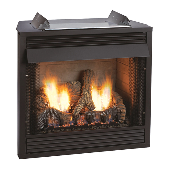
Comfort Systems
Deluxe Vent-Free Universal Fireboxes
ANSI Z21.91 Ventless Fireplace Enclosures for Gas Fired
Decorative Type Unvented Room Heaters
WARNING: If the information in these instructions are not
followed exactly, a fire or explosion may result causing
property damage, personal injury or loss of life.
— Do not store or use gasoline or other flammable vapors
and liquids in the vicinity of this or any other appliance.
— WHAT TO DO IF YOU SMELL GAS
•
Do not try to light any appliance.
•
Do not touch any electrical switch; do not use any
phone in your building.
•
Immediately call your gas supplier from a neigh-
bor's phone. Follow the gas supplier's instruc-
tions.
•
If you cannot reach your gas supplier, call the fire
department.
— Installation and service must be performed by a quali-
fied installer, service agency or the gas supplier.
DO NOT ATTEMPT TO MODIFY OR ALTER THE CONSTRUC-
TION OF THE FIREBOX OR ITS COMPONENTS. ANY MODI-
FICATION OR ALTERATION OF CONSTRUCTION MAY VOID
THE WARRANTY OF THIS FIREBOX.
CHILDREN AND ADULTS SHOULD BE ALERTED TO THE
HAZARDS OF HIGH SURFACE TEMPERATURE AND
SHOULD STAY AWAY TO AVOID BURNS OR CLOTHING IG-
NITION.
YOUNG CHILDREN SHOULD BE CAREFULLY SUPERVISED
WHEN THEY ARE IN THE SAME ROOM AS THE FIREBOX.
INSTALLATION INSTRUCTIONS
AND OWNER'S MANUAL
GAS-FIRED
Installer:
Consumer: Retain this manual for future reference.
WARNING:
tion, service or maintenance can cause injury or property
damage. Refer to this manual. For assistance or additional
information, consult a qualified installer, service agency or
the gas supplier.
Carefully review the instructions supplied with the decora-
tive type unvented room heater for the minimum fireplace
size requirement.
DO NOT INSTALL A VENT-FREE LOG SET IN THIS FIREBOX,
UNLESS THIS FIREBOX MEETS THE MINIMUM DIMENSIONS
REQUIRED FOR THE INSTALLATION.
UNIVERSAL FIREBOX FOR
ALL VENT-FREE LOG SETS
MODELS
VFD32FB0L-2
VFD36FB0L-2
VFD32FB2CL-2
VFD36FB2CL-2
VFD32FB2DL-2
VFD36FB2DL-2
VFD32FB2ML-4 VFD36FB2ML-4 VFD42FB2ML-4
VFD32FB0F-2
VFD36FB0F-2
VFD32FB2CF-2
VFD36FB2CF-2
VFD32FB2DF-2
VFD36FB2DF-2
VFD32FB2MF-4 VFD36FB2MF-4 VFD42FB2MF-4
Leave this manual with the appliance.
FOR USE ONLY WITH A LISTED GAS-FIRED
UNVENTED DECORATIVE ROOM HEATER NOT TO EX-
CEED 40,000 BTU/H.
DO NOT BUILD A WOOD FIRE.
Improper installation, adjustment, altera-
VFD42FB0L-2
VFD42FB2CL-2
VFD42FB2DL-2
VFD42FB0F-2
VFD42FB2CF-2
VFD42FB2DF-2
Page 1
Advertisement
Table of Contents

Related Manuals for Empire VFD32FB0L-2


Summary of Contents for Empire VFD32FB0L-2
-
Page 1: Installation Instructions
INSTALLATION INSTRUCTIONS EMPIRE EMPIRE AND OWNER'S MANUAL Comfort Systems UNIVERSAL FIREBOX FOR ALL VENT-FREE LOG SETS Deluxe Vent-Free Universal Fireboxes MODELS VFD32FB0L-2 VFD36FB0L-2 VFD42FB0L-2 VFD32FB2CL-2 VFD36FB2CL-2 VFD42FB2CL-2 VFD32FB2DL-2 VFD36FB2DL-2 VFD42FB2DL-2 VFD32FB2ML-4 VFD36FB2ML-4 VFD42FB2ML-4 VFD32FB0F-2 VFD36FB0F-2 VFD42FB0F-2 VFD32FB2CF-2 VFD36FB2CF-2 VFD42FB2CF-2 VFD32FB2DF-2... -
Page 2: Table Of Contents
TABLE OF CONTENTS SECTION PAGE Important Safety Information ..................3 Clearances ......................4-5 Firebox Installation Instructions ................6-8 Installing Hood ......................8-9 Gas Line Connection ....................9 Optional Fresh Air Kit Installation Instructions ...........10-12 Optional Single Speed Blower Installations Instructions ........13-15 Junction Box Wiring Installation Instructions ............16 Maintenance ......................16 Parts List ......................17-19 Parts View ......................20... -
Page 3: Important Safety Information
It is imperative that control compartment, burners and circulating air passageways of the appliance be kept clean. This Empire Comfort Systems, Inc. firebox and its - Installation and/or use of any component part components have been tested and will operate safely... -
Page 4: Clearances
CLEARANCES Sidewall Clearances: The clearance from the inside of the firebox COMBUSTIBLE 2 X 4 to perpendicular combustible side wall should not be less than FINISHED WALL HEADER OR MANTEL 6". See Figure 1. Firebox Side and Back Clearances: The firebox outer casing side FINISHED WITH TRIM KIT OR and back flanges are zero clearance to combustibles. NON-COMBUSTIBLE MATERIAL AS DESIRED. Top Framing and Finishing: Combustible framing may rest on STAND OFF top of standoffs. Combustible finishing materials may extend... -
Page 5: Clearances
CLEARANCES Ceiling Clearances: The ceiling height should not be less than 42" from the top of the hood. See Figure 3. Mantel Clearances: Vent free firebox models must use the hood supplied with the firebox, or one of the optional hood kits available for each model. If a combustible mantel is installed, it must meet the clearance requirements detailed below. Grate Clearance: The minimum clearance between the front legs of the grate and front edge of the firebox is 2". -
Page 6: Firebox Installation Instructions
FIREBOX INSTALLATION INSTRUCTIONS Any vent-free Gas Log Heater must be “For use with approved ANSI At this point, you should have decided what components to include Z21.11.2 unvented room heater.” in your installation, and where the firebox is to be located. If this has not been done, stop and consult your dealer for assistance Follow and complete the installation instructions of the gas log set with this planning. - Page 7 FIREBOX INSTALLATION INSTRUCTIONS (continued) OUTER FIREBOX DIMENSIONS DELUXE DELUXE LOUVERED FLUSH INNER FIREBOX DIMENSIONS SIDE VIEW TOP VIEW OUTER FIREBOX DIMENSIONS (in inches) INNER FIREBOX DIMENSIONS (in inches) LOUVERED FLUSH INDEX INDEX VFD32 VFD36 VFD42 LETTER LETTER VFD32 VFD36 VFD42 VFD32 VFD36 VFD42...
-
Page 8: Installing Hood
FIREBOX INSTALLATION INSTRUCTIONS (continued) Locating Firebox Place firebox in framing opening. Use the four (4) framing brackets provided on the firebox to attach firebox to framing. Different hole locations can be used for finishing materials with thicknesses of 3/8", 1/2" and 3/4". Attach these materials with screws provided, two (2) per framing bracket. See Figure 8. Framing brackets should fit directly against framing material. Use at least one (1) nail per bracket to secure in place. FIREBOX OPENING Check squareness of the firebox prior to securing to framed opening. -
Page 9: Gas Line Connection
INSTALLING HOOD (continued) Extended Hoods If your non-combustible facing material is over 1" in thickness that will be used to finish this firebox, an extended hood is available that will extend out 2" farther out into the room. Contact your local dealer for details. VB4H32BL Standard Black VB4H36BL Standard Black VB4H42BL Standard Black VB4H32BR Polished Brass VB4H36BR Polished Brass VB4H42BR Polished Brass VB4H32SS Stainless Steel VB4H36SS Stainless Steel VB4H42SS... -
Page 10: Optional Fresh Air Kit Installation Instructions
OPTIONAL FRESH AIR KIT INSTALLATION INSTRUCTIONS FOR DELUXE AND PREMIUM FIREBOXES The optional Fresh Air Kit is designed to introduce outside air to the firebox as desired. It must be installed prior to, or at the time of firebox installation to framing. The Fresh Air kit must be installed prior to the installation of wall- board or other finishing materials around the unit. Hardware needed (not provided): 4”... - Page 11 OPTIONAL FRESH AIR KIT INSTALLATION INSTRUCTIONS FOR DELUXE AND PREMIUM FIREBOXES Push the handle for “Open” position and pull the handle for Completion of Air Kit installation the “Closed” position. See Figure 17. 1. Determine the length of 4” Dia. rigid or flex duct connector (installer supplied) you will need from the firebox/fireplace to CLOSED OPEN...
- Page 12 OPTIONAL FRESH AIR KIT INSTALLATION INSTRUCTIONS FOR DELUXE AND PREMIUM FIREBOXES PARTS LIST INDEX NO. PART NO. DESCRIPTION 29259 Outside Air Vent Assembly 29257 Slide Assembly 29263 Handle Retainer Hardware Pack R-3580, PHILLIPS TRUSS HEAD SCREW 10 X ½ - QTY - 2 R-2737, HEX HEAD SCREW 10 X ½...
-
Page 13: Optional Single Speed Blower Installations Instructions
OPTIONAL SINGLE SPEED BLOWER INSTALLATION INSTRUCTIONS Attention: Install blower assembly before connecting gas inlet A factory installed junction box is located on the lower right supply line. side of the firebox. Wiring must be fed to the junction box and Wiring attached to the receptacle that is provided. From right side of The appliance, when installed, must be electrically grounded in the firebox, remove the screw securing the junction box as- accordance with local codes or, in the absence of local codes,... - Page 14 OPTIONAL SINGLE SPEED BLOWER INSTALLATION INSTRUCTIONS 4. Insert blower assembly into interior, bottom of firebox. Posi- One fan control wire will have a 1/4” female terminal that must tion blower assembly so that you align the notch on back of be attached to the open terminal on the blower motor. See blower assembly with the center screw on firebox back, then Figure 26, Connection A.
-
Page 15: Optional Single Speed Blower Installations Instructions
OPTIONAL SINGLE SPEED BLOWER INSTALLATION INSTRUCTIONS Blower Motor 110 VOLT AC The blower motor does not have oiling holes. Do not attempt to oil JUNCTION BOX the blower motor. FAN/MOTOR ASSEMBLY Blower Wheels The blower wheels will collect lint and could require periodic clean- ing. -
Page 16: Junction Box Wiring Installation Instructions
JUNCTION BOX WIRING INSTALLATION INSTRUCTIONS CAUTION: ALL WIRING SHOULD BE DONE BY A QUALIFIED ELECTRICIAN AND SHALL BE IN COMPLIANCE WITH ALL LOCAL, CITY AND STATE BUILDING CODES. BEFORE MAKING THE ELECTRICAL CONNECTION, MAKE SURE THAT MAIN POWER SUPPLY IS DISCONNECTED. THE APPLIANCE, WHEN INSTALLED, MUST BE ELECTRICALLY GROUNDED IN ACCORDANCE WITH LOCAL CODES OR, IN THE ABSENCE OF LOCAL CODES, WITH THE NATIONAL ELECTRICAL CODE ANSI/NFPA 70 (LATEST EDITION) A factory installed junction box is located on the lower right hand side of the firebox. Wiring must be fed to the junction box and... -
Page 17: Parts List
PARTS LIST Index Index Part No. Description Part No. Description VFD32FB(0L,CL,DL,ML,0F,CF,DF,MF) VFD36FB(0L,CL,DL,ML,0F,CF,DF,MF) 17149 Top Standoff (Qty 2) 17247 Top Standoff (Qty 2) 17169 Upper Louver 18807 Upper Louver 10554 Framing Bracket (Qty 4) 10554 Framing Bracket (Qty 4) 17170 Lower Louver 18808 Lower Louver 17162... - Page 18 PARTS LIST Index Part No. Description VFD42FB(0L,CL,DL,ML,0F,CF,DF,MF) 17247 Top Standoff (Qty 2) 17187 Upper Louver 10554 Framing Bracket (Qty 4) 17188 Lower Louver 17162 Junction Box Assembly R3492 Receptacle R3491 Cover, Junction Box Bracket, Top Brick Retainer (Aged Brick 21642 Models) (Qty 2) Bracket, Top Brick Retainer (Refractory &...
-
Page 19: Parts View
PARTS VIEW 25476-8-0114 Page 19... -
Page 20: Accessories
ACCESSORIES Accessory Description Model Numbers Fan Kit Designed to provide forced air flow. FBB5 Variable Speed Control Kit Wall mounted variable speed control for use SCV-1 with FBB5 blower Brick Liners Contact dealer for all available Deluxe Firebox optional liner kits Fresh Air Kit Deluxe and Premium Fireboxes BVA-1 Frame Kits 3-Piece Frame Kits... - Page 21 ACCESSORIES (continued) Extended 4" Hoods Extended hoods that extend out 2" farther than the standard hoods, to accommodate thicker surround Contact dealer for all avail- materials. able optional hood acces- sories Available as optional kits in Brass, Hammered Pew- ter, and Stainless Steel finishes. Louvers Styles include Slat, Mission, Arch, and Leaf Patterns.
-
Page 22: Master Parts Distributor List
MASTER PARTS DISTRIBUTOR LIST To Order Parts Under Warranty, please contact your local Empire dealer. See the dealer locator at www.empirecomfort. com. To provide warranty service, your dealer will need your name and address, purchase date and serial number, and the nature of the problem with the unit. -
Page 23: Warranty
WARRANTY Empire Comfort Systems Inc. warranties this hearth product to be free from defects at the time of purchase and for the periods speci- fied below. Hearth products must be installed by a qualified technician and must be maintained and operated safely, in accordance with the instructions in the owner’s manual. This warranty applies to the original purchaser only and is not transferable. All warranty repairs must be accomplished by a qualified gas appliance technician.
Need help?
Do you have a question about the VFD32FB0L-2 and is the answer not in the manual?
Questions and answers