Table of Contents
Advertisement
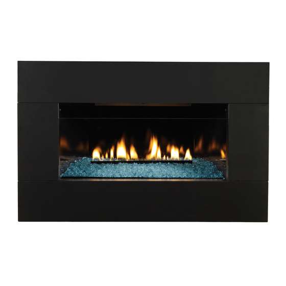
Loft Vent Free Fireplace Insert
Shown without required front.
Installer:
Leave this manual with the appliance.
Consumer: Retain this manual for future reference.
WARNING: If the information in these instructions
are not followed exactly, a fire or explosion may
result causing property damage, personal injury
or loss of life.
— Do not store or use gasoline or other flammable
vapors and liquids in the vicinity of this or any
other appliance.
— WHAT TO DO IF YOU SMELL GAS
•
Do not try to light any appliance.
•
Do not touch any electrical switch; do not use
any phone in your building.
•
Immediately call your gas supplier from a
neighbor's phone. Follow the gas supplier's
instructions.
•
If you cannot reach your gas supplier, call the
fire department.
— Installation and service must be performed by a
qualified installer, service agency or the gas sup-
plier.
INSTALLATION INSTRUCTIONS
AND OWNER'S MANUAL
GAS-FIRED
UNVENTED
GAS FIREPLACE
MODELS
VFL20IN3210(N,P)-1
VFL20IN32(N,P)-1
VFL20IN92(N,P)-1
VFL28IN32(N,P)-1
VFL28IN92(N,P)-1
This appliance may be installed in an aftermarket,
permanently located, manufactured (mobile) home,
where not prohibited by local codes.
This appliance is only for use with the type of gas
indicated on the rating plate. This appliance is not
convertible for use with other gases.
This is an unvented gas-fired heater. It uses air (oxy-
gen) from the room in which it is installed. Provisions
for adequate combustion and ventilation air must be
provided. Refer to page 13.
WARNING: If not installed, operated and maintained
in accordance with the manufacturer's instructions,
this product could expose you to substances in fuel
or from fuel combustion which can cause death or
serious illness.
WATER VAPOR: A BY-PRODUCT OF UNVENTED ROOM
HEATERS
Water vapor is a by-product of gas combustion. An
unvented room heater produces approximately one
ounce (30ml) of water for every 1,000 BTU's (.3KW's)
of gas input per hour. Refer to page 13.
Page 1
Advertisement
Table of Contents
Troubleshooting

Subscribe to Our Youtube Channel
Related Manuals for Empire VFL20IN3210(N,P)-1


Summary of Contents for Empire VFL20IN3210(N,P)-1
- Page 1 INSTALLATION INSTRUCTIONS AND OWNER'S MANUAL Loft Vent Free Fireplace Insert UNVENTED GAS FIREPLACE MODELS VFL20IN3210(N,P)-1 VFL20IN32(N,P)-1 VFL20IN92(N,P)-1 VFL28IN32(N,P)-1 VFL28IN92(N,P)-1 GAS-FIRED Shown without required front. Installer: Leave this manual with the appliance. Consumer: Retain this manual for future reference. This appliance may be installed in an aftermarket, WARNING: If the information in these instructions permanently located, manufactured (mobile) home, are not followed exactly, a fire or explosion may where not prohibited by local codes.
-
Page 2: Table Of Contents
TABLE OF CONTENTS SECTION PAGE IMPORTANT SAFETY INFORMATION ..................3 SAFETY INFORMATION FOR USERS OF LP-GAS ..............4 IMPORTANT INSTALLATION GUIDELINES ................. 5 INTRODUCTION ........................... 6 SPECIFICATIONS ......................... 7 INSTALLATION IN A FIREPLACE ....................8 FIREPLACE INSERT DIMENSIONS ..................... 9 BUILT-IN FIREPLACE INSTALLATION .................. -
Page 3: Important Safety Information
IMPORTANT SAFETY INFORMATION DANGER: Indicates a hazardous situation which, if not avoided, will • WARNING! This fireplace needs fresh air for ventilation to result in death or serious injury. run properly. This fireplace has an ODS (oxygen depletion sensor) which will shut down the heater if adequate fresh air is WARNING: Indicates a hazardous situation which, if not avoided, not available. See troubleshooting section in the instructions. -
Page 4: Safety Information For Users Of Lp-Gas
SAFETY INFORMATION FOR USERS OF LP-GAS Propane (LP-Gas) is a flammable gas which can cause fires SOME POINTS TO REMEMBER and explosions. In its natural state, propane is odorless and • Learn to recognize the odor of LP-gas. Your local LP-Gas colorless. You may not know all the following safety precautions Dealer can give you a "Scratch and Sniff" pamphlet. Use it to which can protect both you and your family from an accident. find out what the propane odor smells like. If you suspect that Read them carefully now, then review them point by point with your LP-Gas has a weak or abnormal odor, call your LP-Gas the members of your household. Someday when there may not... -
Page 5: Important Installation Guidelines
IMPORTANT INSTALLATION GUIDELINES Proper Primary Airflow into Burner For proper burner operation and flame appearance, the flow of primary air into the venturi tube, located on the rear of the burner, must not be reduced. This flow of air is reduced if dirt, lint or other obstructions build-up around or inside the venturi. -
Page 6: Introduction
INTRODUCTION Instructions to Installer Notice: During initial firing of this unit, its paint will bake out, and Installer must leave instruction manual with owner after smoke will occur. To prevent triggering of smoke alarms, ventilate installation. the room in which the unit is installed. Installer must have owner fill out and mail warranty card supplied with unvented room heater. -
Page 7: Specifications
Variable Speed Blower DG-1-BKP Decorative Glass Black Polished DG-1-BUC Decorative Glass Blue Clear DG-1-CLF Decorative Glass Frost Optional decorative glass and rocks are available in several different sizes and colors. Contact your Empire Dealer for more information. 31385-6-0714 Page 7... -
Page 8: Installation In A Fireplace
INSTALLATION IN A FIREPLACE Before beginning, check to make sure there is no hidden Install the insert without the surround panels attached and damage to the unit. Take a minute and plan out the gas and make all gas venting and electrical connections. If the control electrical route. -
Page 9: Fireplace Insert Dimensions
FIREPLACE INSERT DIMENSIONS When planning a fireplace insert installation, it’s necessary to or remote control - are desired. determine: • Electrical supply requirements for optional blower. • Gas supply piping. (120V, 60Hz, 1 Amp) • Electrical connections - for optional blower •... -
Page 10: Built-In Fireplace Installation
BUILT-IN FIREPLACE INSTALLATION In planning the installation for the fireplace, it is necessary to At this point, you should have decided what components to include determine where the unit is to be installed and whether optional in your installation, and where the fireplace is to be located. If this accessories are desired. -
Page 11: Vfl20In Fireplace With Surround Dimensions
VFL20IN FIREPLACE WITH SURROUND DIMENSIONS DF20MBL DF20LBL DF20GBL 31385-6-0714 Page 11... -
Page 12: Vfl28In Fireplace With Surround Dimensions
VFL28IN FIREPLACE WITH SURROUND DIMENSIONS 37” 23 1/2” 14 1/2” 28” 4 9/32” DF28GBL 43” 28 5/8” 1 3/4” DF28LBL 40 5/8” 24 1/2” 26 1/2” 2” 2 11/32” DF28MBL Page 12 31385-6-0714... -
Page 13: Water Vapor: A By-Product Of Unvented Room Heaters
WATER VAPOR: A BY-PRODUCT OF UNVENTED ROOM HEATERS Water vapor is a by-product of gas combustion. An unvented room The following steps will help insure that water vapor does not heater produces approximately one ounce (30ml) of water for every become a problem. - Page 14 PROVISIONS FOR ADEQUATE COMBUSTION & VENTILATION AIR (continued) Ventilation Air From Outdoors The space in the above example is a confined space because the Provide extra fresh air by using ventilation grills or ducts. You must actual BTU/Hr used is more than the maximum BTU/HR the space provide two permanent openings: one within 12"...
-
Page 15: Gas Supply
GAS SUPPLY The gas pipeline can be brought in through the right or left side of Installing the Main Gas Cock the appliance. The insert has a Flexline with shutoff valve located on Each appliance should have its own manual gas cock. the right side when facing the unit. See Figures 9 and 10. Consult A manual main gas cock should be located in the vicinity of the unit. -
Page 16: Clearances
GAS SUPPLY (continued) Checking Manifold Pressure Propane gas will have a manifold pressure approximately 10.0"w.c. MILLIVOLT VALVES at the pressure regulator outlet with the inlet pressure to the pressure regulator from a minimum of 11.0"w.c. for the purpose of input Natural gas will have a manifold pressure of approximately 3.5" w.c. adjustment to a maximum of 13.0"w.c. - Page 17 CLEARANCES (continued) VFL20 Series Figure 12 VFL28 Series Figure 13 31385-6-0714 Page 17...
- Page 18 CLEARANCES (continued) Figures 14 and 15 pertain to VFL(20,28)IN Series. Surround Clearances Figure 14 Glass Front Clearances Figure 15 Page 18 31385-6-0714...
-
Page 19: Combustible Materials
COMBUSTIBLE MATERIALS Combustible Material No greeting cards, stockings or ornamentation of any type should be No greeting cards, stockings or ornamentation of any type should placed on or attached to the fireplace. This is a heating appliance. be placed on or attached to the fireplace. The flow of heat can The flow of heat can ignite combustibles. -
Page 20: Alternate On/Off Switch Installation For Millivolt Systems
ALTERNATE ON/OFF SWITCH INSTALLATION FOR MILLIVOLT SYSTEMS WIRING THE FIREPLACE Remove the switch knockout on the DF(20,28)BL surround, then install the ON/OFF switch into the switch bracket. WARNING Connect the low voltage wires from the gas valve to the ON/OFF switch. Electrical wiring must be installed by a licensed electrician. -
Page 21: Decorative Accessory Installation
DECORATIVE ACCESSORY INSTALLATION WARNING Failure to position the parts in accordance with the dia- grams and instructions below or failure to use only parts specifically approved for use with this heater may result in property damage or personal injury. Notice: The Loft series burners may be operated with or without the Decorative accessory options. Follow the directions below should you choose to enhance your Loft burner with any one of the available decorative options. -
Page 22: Operation Instructions/Flame Appearance
OPERATION INSTRUCTIONS/FLAME APPEARANCE Flames from the pilot (front center of burner) as well as the main flame should be visually checked as the fireplace is installed. In normal operation at full rate after 10 to 15 minutes, the flame appearance should be sets of yellow flames. Notice: All flames will be random by design, flame height will go up and down. -
Page 23: Millivolt Control Valve Lighting Instructions
MILLIVOLT CONTROL VALVE LIGHTING INSTRUCTIONS FOR YOUR SAFETY READ BEFORE LIGHTING WARNING: If you do not follow these instructions exactly, a fire or explosion may result causing property damage, personal injury or loss of life. A. This appliance has a pilot which must be lighted by department. hand. When lighting the pilot, follow these instructions C. Use only your hand to push in or turn the gas control exactly. -
Page 24: Valve Wiring
MILLIVOLT CONTROL VALVE WIRING Label all wires prior to disconnection when servicing controls. Wiring Remote Receiver errors can cause improper and dangerous operation. Verify proper Use the following steps to place the remote receiver adjacent to operation after servicing. the gas valve. Attention: The remote receiver bracket is not used in this Millivolt thermopile is self powered, gas valve does not require 110 installation. -
Page 25: Multifunction Remote Ip (Mrip) Lighting Instructions
MULTIFUNCTION REMOTE IP (MRIP) LIGHTING INSTRUCTIONS FOR YOUR SAFETY READ BEFORE LIGHTING WARNING: If you do not follow these instructions exactly, a fire or explosion may result causing property damage, personal injury or loss of life. A. This appliance has a pilot which must be lighted by hand. When C. -
Page 26: Wiring
WIRING MULTIFUNCTION REMOTE IP (MRIP) Note: Valve Shown with Manual Hi/Lo. If any of the original wire as supplied with this unit must be replaced, it must be replaced with equivalent gauge and tem- perature rated wire. This appliance is only for use with the type of gas indicated on the rating plate and may be installed in an aftermarket, permanently located, manufactured (mobile) home where not prohibited by local codes. -
Page 27: Specifications
MULTIFUNCTION REMOTE IP (MRIP) SPECIFICATIONS Technical Data WARNING Remote Control FIRE HAZARD. CAN CAUSE SEVERE INJURY OR DEATH. Supply voltage 4.5 V (three 1.5 V AAA batteries) THE RECEIVER CAUSES IGNITION OF THE APPLIANCE. THE APPLIANCE CAN TURN ON SUDDENLY. KEEP AWAY Ambient temperature 0-50°C (32 - 122°F) FROM THE APPLIANCE BURNER WHEN OPERATING THE... -
Page 28: Operating Instructions
MULTIFUNCTION REMOTE IP (MRIP) OPERATING INSTRUCTIONS 5.25 VDC ELECTRONIC CONTROL VALVE Follow the SAFETY and LIGHTING INSTRUCTIONS for In- termittent Pilot controls found in this manual, and on labels The electronic control valve system includes the ability to switch found in the control compartment located in the lower cavity the pilot from a standing pilot mode to an intermittent pilot mode. -
Page 29: Remote Instructions
MULTIFUNCTION REMOTE IP (MRIP) REMOTE INSTRUCTIONS TRANSMITTER (REMOTE CONTROL WITH LCD DISPLAY) RECEIVER The Proflame Transmitter uses a streamline design with a simple The Proflame Receiver connects directly to the gas valve and button layout and informative LCD display See Figure 25. stepper motor with a wiring harness. - Page 30 MULTIFUNCTION REMOTE IP (MRIP) REMOTE INSTRUCTIONS OPERATING PROCEDURE Turn on the Appliance Initializing the System for the first time Press the ON/OFF Key on the Transmitter. The Transmitter dis- Install the 4 AA batteries into the receiver battery bay. Note the play will show all active Icons on the screen. At the same time polarity of battery and insert into the battery bay as indicated on the Receiver connects the thermopile to the gas valve millivolt coil the Battery cover (+/-).
- Page 31 MULTIFUNCTION REMOTE IP (MRIP) REMOTE INSTRUCTIONS Remote Flame Control The Proflame GTM has six flame levels. With the system on, and the flame level at the maximum in the appliance, pressing the Down Arrow Key once will reduce the flame height by one step un- til the flame is turned off.
- Page 32 MULTIFUNCTION REMOTE IP (MRIP) REMOTE INSTRUCTIONS ROOM THERMOSTAT ( Transmitter Operation) Smart Thermostat (Transmitter Operation) The Remote Control can operate as a room thermostat. The ther- The Smart Thermostat function adjusts the flame height in accor- mostat can be set to a desired temperature to control the comfort dance to the difference between the set point temperature and the level in a room.
- Page 33 MULTIFUNCTION REMOTE IP (MRIP) REMOTE INSTRUCTIONS KEY LOCK Receiver This function will lock the keys to avoid unsupervised operation. The life span of the Receiver batteries depends on various factors: To activate this function, press the MODE and the UP Arrow Key at quality of the batteries used, the number of ignitions of the appli- the same time.
- Page 34 TROUBLESHOOTING MULTIFUNCTION REMOTE IP (MRIP) Brief Description of the Components The gas valve is fitted with a manual HI/LO knob to allow for man- ual modulation of the gas outlet pressure to the appliance burner. The controls are designed to be used with either LPG or Natural Gas and can be converted by use of an OEM supplied conversion kit.
-
Page 35: Troubleshooting
TROUBLESHOOTING MULTIFUNCTION REMOTE IP (MRIP) If the DFC giving signal lock out: Verify the electrical connections’ integrity and The board should be unlocked to make sure they are in accordance with the relevant reinitiate a pilot flame ignition (for Is the DFC board in system wiring diagram. - Page 36 TROUBLESHOOTING MULTIFUNCTION REMOTE IP (MRIP) Page 36 31385-6-0714...
-
Page 37: Pilot Flame Characteristics
MULTIFUNCTION REMOTE IP (MRIP) PILOT FLAME CHARACTERISTICS Figures 40 and 42 show a correct pilot flame pattern. The correct flame will be blue and will extend beyond the thermocouple. The flame will surround the thermocouple just below the tip. A slight yellow flame may occur where the pilot flame and main burner flame meet. -
Page 38: Cleaning And Servicing
MULTIFUNCTION REMOTE IP (MRIP) PILOT FLAME CHARACTERISTICS Cleaning and Pilot Maintenance Oxygen Depletion Sensor Pilot When the pilot has a large yellow tip flame, clean the Oxygen Depletion Sensor as follows: Clean the ODS pilot by loosening nut B from the pilot tubing. When this procedure is required, grasp nut A with an open end wrench. -
Page 39: Troubleshooting
TROUBLESHOOTING SYMPTOMS, POSSIBLE CAUSES AND CORRECTIONS 1. When ignitor button is pressed, there is no spark at ODS/ problem could be caused by either low gas pressure or dirty or pilot. partially clogged ODS/pilot - Contact local gas company. a. Ignitor electrode positioned wrong - Replace pilot. f. Thermocouple damaged - Replace thermocouple. b. -
Page 40: Vfl20In Parts List
VFL20IN PARTS LIST PART NO. INDEX DESCRIPTION VFL20IN3 VFL20IN3 VFL20IN9 (10,000 BTU) 27546BL 27546BL 27546BL FIREBOX BAFFLE 27406 27406 27406 BURNER ASSEMBLY COVER 28056 28056 31251 FIREBOX BOTTOM - NAT 28056 28056 31952 FIREBOX BOTTOM - LP 28055 28055 31669 BLOWER SHIELD 27085 27085... -
Page 41: Vfl28In Parts List
VFL28IN PARTS LIST PART NO INDEX DESCRIPTION VFL28IN3 VFL28IN9 27559BL 27559BL FIREBOX BAFFLE 27571 27571 BURNER ASSEMBLY COVER 27554 31345 FIREBOX BOTTOM 28055 31669 BLOWER SHIELD 27085 27085 BURNER SUPPORT R7624 R7624 AIR SHUTTER R7572 R7572 JAMB NUT 1/4"-18 NPS 27086 27086 BURNER END SUPPORT... -
Page 42: Exploded View
EXPLODED VIEW 36 37 20 MILLIVOLT VALVE ASSEMBLY IP VALVE ASSEMBLY Page 42 31385-6-0714... -
Page 43: Master Parts Distributor List
MASTER PARTS DISTRIBUTOR LIST To Order Parts Under Warranty, please contact your local Empire dealer. See the dealer locator at www.empirecomfort. com. To provide warranty service, your dealer will need your name and address, purchase date and serial number, and the nature of the problem with the unit. -
Page 44: Df(20,28Lbl Surround Fronts For Fireplaces
DF(20,28)LBL SURROUND FRONTS FOR FIREPLACES This fireplace requires a surround, available from your Empire Comfort Systems dealer. The surround shown below allows the fireplace to be installed as an insert in an existing fireplace or in a mantel. For elevated installation in a wall, see the surrounds on the following page. -
Page 45: Surround Fronts For Wall Mounts
SURROUND FRONTS FOR WALL MOUNTS The fireplace requires a surround, available from your Empire Comfort Systems dealer. The surrounds shown below allow the fireplace to be installed elevated in a wall. For installation as an insert in an existing fireplace or in a mantel, see the fronts on the previous page. -
Page 46: Appliance Service History
APPLIANCE SERVICE HISTORY Date Dealer Name Service Technician Name Service Performed/Notes Page 46 31385-6-0714... -
Page 47: Warranty
WARRANTY Empire Comfort Systems Inc. warranties this hearth product to be free from defects at the time of purchase and for the periods speci- fied below. Hearth products must be installed by a qualified technician and must be maintained and operated safely, in accordance with the instructions in the owner’s manual. - Page 48 Empire Comfort Systems Inc. 918 Freeburg Ave. Belleville, IL 62220 If you have a general question about our products, please e-mail us at info@empirecomfort.com. If you have a service or repair question, please contact your dealer. www.empirecomfort.com Page 48 31385-6-0714...
Need help?
Do you have a question about the VFL20IN3210(N,P)-1 and is the answer not in the manual?
Questions and answers