Table of Contents
Advertisement
Quick Links
Installer:
Leave this manual with the
appliance.
Consumer: Retain this manual for future
reference.
This appliance may be installed in an after-
market permanently located, manufactured
(mobile) home, where not prohibited by local
codes.
This appliance is only for use with the type of
gas indicated on the rating plate. This fireplace
is not convertible for use with other gases.
WARNING: If the information in these
instructions are not followed exactly, a fire
or explosion may result causing property
damage, personal injury or loss of life.
— Do not store or use gasoline or other
flammable vapors and liquids in the
vicinity of this or any other appliance.
— WHAT TO DO IF YOU SMELL GAS
•
Do not try to light any appliance.
•
Do not touch any electrical switch; do
not use any phone in your building.
•
Immediately call your gas supplier
from a neighbor's phone. Follow the
gas supplier's instructions.
•
If you cannot reach your gas supplier,
call the fire department.
— Installation and service must be per-
formed by a qualified installer, service
agency or the gas supplier.
INSTALLATION INSTRUCTIONS
AND OWNER'S MANUAL
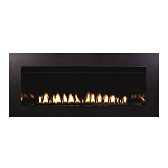
CONTEMPORARY LINEAR
VENT-FREE GAS FIREPLACE
MODELS
GAS-FIRED
VFLL38FP(3,9)0L25(N,P)-1
VFLL38FP(3,9)0L(N,P)-1
VFLL48FP(3,9)0L(N,P)-1
MH46389
Vent-Free Linear Logset Shown
WATER VAPOR: A BY-PRODUCT OF
UNVENTED ROOM HEATERS
Water vapor is a by-product of gas combus-
tion. An unvented room heater produces
approximately one (1) ounce (30ml) of water
for every 1,000 BTU's (.3KW's) of gas input
per hour. Refer to page 13.
This is an unvented gas-fired heater. It uses
air (oxygen) from the room in which it is
installed. Provisions for adequate combustion
and ventilation air must be provided. Refer to
pages 13 - 14.
WARNING: If not installed, operated and
maintained in accordance with the
manufacturer's instructions, this product
could expose you to substances in fuel or
from fuel combustion which can cause death
or serious illness.
Page 1
Advertisement
Table of Contents
Troubleshooting

Related Manuals for Empire VFLL38FP(3,9)0L25(N,P)-1


Summary of Contents for Empire VFLL38FP(3,9)0L25(N,P)-1
- Page 1 Leave this manual with the VENT-FREE GAS FIREPLACE appliance. Consumer: Retain this manual for future MODELS GAS-FIRED reference. VFLL38FP(3,9)0L25(N,P)-1 This appliance may be installed in an after- VFLL38FP(3,9)0L(N,P)-1 market permanently located, manufactured VFLL48FP(3,9)0L(N,P)-1 (mobile) home, where not prohibited by local MH46389 codes.
-
Page 2: Before You Start
BEFORE YOU START Read the soot prevention information on page 4. Installation Considerations - Fireplace Installation Guide- lines Read the safety information on Pages 9 - 11. In planning the installation for the fireplace, determine where the Frame the opening. See pages 22 - 23. unit is to be installed. The fireplace can be mounted on any of these surfaces: Install the gas lines. -
Page 3: Carton Contents & Hardware Pack
CARTON CONTENTS & HARDWARE PACK CARTON CONTENTS HARDWARE PACK CONTENTS - VFLL(28,48)FP(3,7) #10-32 X ½” HEX HEAD SCREW G LA SS W ITH CA HA ND LE #10-32 X ½” STAINLESS HEX HEAD SCREW 1-1/4” PHILLIPS DRYWALL SCREW Items not shown to scale. VFLL(38,48)FP3 SERIES Index Quantity Description... -
Page 4: Important Soot Prevention Steps
• Avoid the use of scented air fresheners while the fire- place is in operation. A residue can be produced which may produce soot. • Avoid the use of decorative or scented candles while the fireplace is in operation. Soot may be produced from the by-products of a burning candle. Some candles also produce soot. • Do not use rock wool (embers) with this fireplace. Figure 2 (1/16" opening shown) • Annual inspection and cleaning by your dealer or qualified service technician is recommended to pre- LP Gas Models- The air shutter setting must be "fully open" vent malfunction and/or sooting. or 1/4" open. See Figure 3 and Table 2 on page 5. • Install optional logs according to the installation in- The air shutter setting must be set to the maximum opening. structions. Do not alter log placement from the pre- scribed layout in this manual. Only use Empire logs specifically made for this fireplace. • Verify the venturi tube is not bent or distorted. The main burner orifice must be centered in the venturi tube for proper combustion and to prevent sooting. NOTICE: Orifice shield removed for photo clarity. Figure 3 Page 4 34380-0-0914... -
Page 5: Product Specifications
PRODUCT SPECIFICATIONS Natural Gas Propane Gas Millivolt Intermittent Pilot Millivolt Intermittent Pilot (IP) (IP) Regulator pressure setting 3.5" w.c. 3.5" w.c. 10.0" w.c. 10.0" w.c. Gas inlet pressure Max. 10.5" w.c. 10.5" w.c. 13.0" w.c. 13.0" w.c. Min. 4.5" w.c. 7.0" w.c. 11.0" w.c. 11.0" w.c. Recommended BTUH BTUH Model Valve Type Orifice Manifold Pressure Type Max. -
Page 6: Table Of Contents
TABLE OF CONTENTS SECTION PAGE Before You Start ........................2 Carton Contents & Hardware Pack ..................3 Important Soot Prevention Steps..................4 Product Specifications ......................5 Introduction ........................... 7 Accessories .......................... 8 Important Safety Information ..................9 - 10 Safety Information for Users of LP-Gas................11 Important Installation Guidelines ..................12 Water Vapor: A By-Product of Unvented Room Heaters ............ 13 Provisions for Adequate Combustion & Ventilation Air ..........13 - 14 Fireplace Dimensions ...................... -
Page 7: Introduction
INTRODUCTION Notice: During initial firing of this unit, its paint will bake out, and Instructions to Installer smoke will occur. To prevent triggering of smoke alarms, ventilate 1. Installer must leave instruction manual with owner after the room in which the unit is installed. installation. 2. Installer must have owner fill out and mail warranty card supplied Installation on Rugs and Tile with unvented room fireplace. If this fireplace is installed directly on carpeting, tile or other 3. Installer should show owner how to start and operate unvented combustible material other than wood flooring the fireplace shall fireplace. -
Page 8: Accessories
ACCESSORIES Accessories for VFLL(38,48)FP30 (Millivolt) Models Remote Control Description Accessories FRBTC Battery Operated Remote Control with Thermostat FRBTP Battery Operated Programmable Remote Control Remote Wall Thermostat (Wireless) ACCESSORIES Part Number Description VFLL38 VFLL48 DF38EHPBL Decorative Front, Eastgate - Black and Pewter DF38WHP DF48WHP Decorative Front, Tidewater - Pewter DF38WBL DF48WBL Decorative Front, Tidewater - Black DF384BL DF484BL Decorative Front, 4" Surround - Black 120 V Lighting Kit - Requires Switch or Rheostat VBP38LCR Liner - Blue Reflective VBP38LKR VBP48LKR Liner - Black Reflective VBP38LWR VBP48LWR Liner - White Reflective VBP38LSS VBP48LSS... -
Page 9: Important Safety Information
IMPORTANT SAFETY INFORMATION Definitions: DANGER DANGER - Indicates a hazardous situation which, if not avoid- ed, will result in death or serious injury. The installer of this product is responsible for the verifying the correct position of the air shutter and adjusting it if required. If not adjusted to the proper opening, a fire, explosion, or production of WARNING - Indicates a hazardous situation which, if not carbon monoxide may result causing property damage, personal avoided, could result in death or serious injury. injury or loss of life. CAUTION - Indicates a hazardous situation which, if not DANGER avoided, could result in minor or moderate injury. The installer of this product is responsible for testing all connections NOTICE - Addresses practices not related to personal injury. for gas leaks. A gas leak will create a situation where a fire, explosion, or production of carbon monoxide may result causing property damage, personal injury or loss of life. - Page 10 During manufacturing, fabricating and shipping, various All fireplaces, whether decorative or heater rated create components of this fireplace are treated with certain oils, films heat. Most television manufacturers recommend not placing or bonding agents. These bonding agents are not harmful but a television near a heat source. Because there is a large may produce annoying smoke and smells as they are burned variety of television manufactures, styles and sizes, it is im- off during initial operation of the fireplace. This is a normal practical to test every potential installation. If you choose to temporary occurrence. A window should be opened during the install a television above or near your fireplace, understand initial bake out period. that Empire Comfort Systems accepts no responsibility for • Correct installation of the optional ceramic fiber logs, proper this decision and any injury or damage due to this application location of the fireplace and annual cleaning are necessary to is the sole responsibility of the owner. Additionally, it is highly avoid potential problems with sooting. Sooting, resulting from recommended to turn off the fireplace and let it cool down improper installation or operation, can settle on surfaces outside before servicing or using the operational buttons located the fireplace. See instructions for proper installation. on the television. In all cases, the television manufacturer’s •...
-
Page 11: Safety Information For Users Of Lp-Gas
SAFETY INFORMATION FOR USERS OF LP-GAS Propane (LP-Gas) is a flammable gas which can cause fires SOME POINTS TO REMEMBER and explosions. In its natural state, propane is odorless and • Learn to recognize the odor of LP-gas. Your local LP-Gas colorless. -
Page 12: Important Installation Guidelines
Avoid the use of scented air fresheners while the fireplace is in operation. Air fresheners produce a residue in the air similar to candles and may produce a soot like substance. Television Considerations Installing a television above a fireplace has become increasingly popular; however, the area above any fireplace gets hot and most TV manufacturers recommend against placing their products near a heat source. If you install a television above this fireplace, Empire Comfort Sys- tems accepts no responsibility for damage or injuries. Follow the television manufacturer’s installation instructions, including any recommendations regarding proximity to heat sources. If you have a TV above your fireplace, turn off the fireplace and let it cool completely before servicing or touching any buttons on the TV. Page 12... -
Page 13: Water Vapor: A By-Product Of Unvented Room Heaters
WATER VAPOR: A BY-PRODUCT OF UNVENTED ROOM HEATERS Water vapor is a by-product of gas combustion. An unvented room The following steps will help insure that water vapor does not heater produces approximately one (1) ounce (30ml) of water for become a problem. every 1,000 BTU's (.3KW's) of gas input per hour. 1. Be sure the heater is sized properly for the application, including ample combustion air and circulation air. Unvented room heaters are recommended as supplemental heat (a 2. If high humidity is experienced, a dehumidifier may be used to room) rather than a primary heat source (an entire house). In most help lower the water vapor content of the air. supplemental heat applications, the water vapor does not create a 3. Do not use an unvented room heater as the primary heat problem. In most applications, the water vapor enhances the low source. - Page 14 PROVISIONS FOR ADEQUATE COMBUSTION & VENTILATION AIR (continued) The space in the above example is a confined space because the Ventilation Air From Outdoors actual BTU/Hr used is more than the maximum BTU/HR the space Provide extra fresh air by using ventilation grills or ducts. You must can support. You must provide additional fresh air. Your options provide two permanent openings: one within 12" of the ceiling are as follows: and one with 12" of the floor. Connect these items directly to the A. Rework worksheet, adding the space of an adjoining room. If outdoors or spaces open to the outdoors. These spaces include the extra space provides an unconfined space, remove door attics and crawl spaces. In most cases for direct communication to adjoining room or add ventilation grills between rooms. See...
-
Page 15: Fireplace Dimensions
FIREPLACE DIMENSIONS GAS LINE ACCESS GAS LINE ACCESS HOLES IN STANDOFF OPTIMUM GAS LINE GAS LINE ACCESS ACCESS VFLL38FP VFLL48FP INDEX DIMENSION DESCRIPTION LETTER Dimensions in Inches The maximum height of firebox face (excluding standoffs) 21-1/8 21-1/8 The maximum width of the firebox face (excluding nailing flanges) 43-1/4 52-3/4 The maximum depth of the firebox 11-1/2 11-1/2 The height of the firebox opening 12-1/16 12-1/16 The width of the firebox opening 38-1/4 The interior depth of the firebox (not shown) 10-1/2... -
Page 16: Framing & Mounting Bracket Installation
FRAMING & MOUNTING BRACKET INSTALLATION NOTE: You must use the framing and middle mounting brack- 6. Locate framing brackets in the envelope pack. The holes in ets that are supplied with the fireplace. The brackets are the framing brackets allow different size boards and different shipped under the burner cover, inside the fireplace. locations for the boards. See Figure 11. Bend the brackets at 90° angles. Install four framing brackets with two 10 x 1/2 1. Locate the three steel middle mounting brackets under the screws (each). See Figures 13 and 14. -
Page 17: Junction Box Wiring Installation
JUNCTION BOX WIRING INSTALLATION CAUTION: ALL WIRING SHOULD BE DONE BY A QUALIFIED 1. To access and install the junction box and wiring, begin by ELECTRICIAN AND SHALL BE IN COMPLIANCE WITH ALL removing the burner cover. Lift it straight up off of the burner LOCAL, CITY AND STATE BUILDING CODES. BEFORE MAK- and set aside. - Page 18 JUNCTION BOX WIRING INSTALLATION 3. Lift the complete burner and valve assembly upward, then turn it sideways in fireplace opening to gain easy access to the junction box. See Figure 19. You may remove the complete burner and valve assembly as shown in Figure 19. Figure 21 5. If only installing the LK5 Accent Light kit, then remove the 7/8” diameter knockout in the back of the junction box, install the 7/8” diameter protective grommet, and connect the wiring with Figure 19 wire nuts as shown in Figure 21. The junction box is located on the right side of the fireplace. There is a solid junction box cover plate included with the Remove the two 5/16” Hex screws that secure the junction box LK5 kit that should be used on the junction box if a duplex to the firebox, and remove the junction box. See Figure 20.
-
Page 19: Gas Supply
GAS SUPPLY Caution: Two gas line installations at the same time are prohibited. fireplace connected; control valve will sustain damage! The access plate to the switching means shall not be opened while Notice: The millivolt gas controls are equipped with a captured screw the heater is in operation. type pressure test point, therefore it is not necessary to provide a The gas pipeline can be brought in through the right or left side of 1/8" test point up stream of the control. the fireplace. The insert has a Flexline with shutoff valve located on When using copper or flex connector use only approved fittings. the left side when facing the unit. See Figures 23 and 24. Consult The fireplace and it’s individual shut off valve must be disconnected the current National Fuel Gas Code, ANSI Z223.1 CAN/CGA-B149 from supply piping system during any pressure testing of that system (.1 or .2) installation code. at test pressures in excess of 1/2 psig (3.5kPa). The fireplace must be isolated from the gas supply piping system Recommended Gas Pipe Diameter by closing its individual manual shut off valve during any pressure Pipe Length Schedule 40 Pipe Tubing, Type L testing of the gas supply piping system at test pressures equal to... -
Page 20: Clearances
12” HEADER 10” Television Considerations 8” Installing a television above a fireplace has become increasingly popular; however, the area above any fireplace gets hot and most 6” TV manufacturers recommend against placing their products near STANDOFFS a heat source. 4” If you install a television above this fireplace, Empire Comfort Sys- NON-COMBUSTIBLE MATERIAL (MAY BE tems accepts no responsibility for damage or injuries. Follow the INSTALLED TO EDGE 2” OF FIREPLACE OPENING) television manufacturer’s installation instructions, including any recommendations regarding proximity to heat sources. COMBUSTIBLES NOT ALLOWED If you have a TV above your fireplace, turn off the fireplace and IN SHADED AREA let it cool completely before servicing or touching any buttons on the TV. -
Page 21: Fireplace Installation
FIREPLACE INSTALLATION Built-In Fireplace Installation 6. Check gas lines for leaks. Built-in installation of this fireplace involves installing the fireplace 7. For VFLL(38,48)FP90 plug power adapter to junction box. into a framed-in enclosure. This makes the front of the fireplace 8. Place batteries in receiver boxes and remotes using instruc- flush with a wall or the front of the fireplace window flush with a tions provided. Verify remote is communicating with receiver. wall. 9. Install optional liners using their instructions. 10a. F or VFLL(38,48)FP30 fireplaces: Connect the remote receiv- Frame in rough opening. Use dimensions shown in Figure 32 for a er to the valve as indicated in the instructions included with conventional rough opening. Use Figure 33 for an elevated instal- the remote and receiver. Light the pilot and turn the valve to lation. Be sure to provide support to the bottom of the fireplace. - Page 22 FIREPLACE INSTALLATION FINISHED FINISHED NON-COMBUSTIBLE WALL WALL BOARD INSTALLED OVER APPLIANCE OPENING NON-COMBUSTIBLE BOARD INSTALLED ON TOP OF APPLIANCE FLUSH WITH FACE FOR TILING OVER FACE OR FIREPLACE 2 1/4” APPLIANCE APPLIANCE OPENING OPENING NON-COMBUSTIBLE BOARD INSTALLED ON BOTH SIDES Figure 28 - Tiling or Non-Combustible Material Application Figure 29 - High Temperature Paint Application Tile or non-combustbile materials can be applied on top of the...
- Page 23 FIREPLACE INSTALLATION Rough Opening for Installing in Wall (Built-In) Rough Opening for Installing in Corner (Built-In) Figure 34 Figure 32 Rough Opening for Elevated Installation (Built-In) Figure 33 TABLE 3 - MINIMUM DIMENSIONS (in inches) FOR FIGURES 28 - 34 VFLL38FP(3,9)0L25 11-3/4* 43-1/2...
-
Page 24: Combustible Materials
COMBUSTIBLE MATERIALS Combustible Material Television Considerations Do not attach combustible material to the mantel of your fireplace. Installing a television above a fireplace has become increasingly This is a fire hazard. popular; however, the area above any fireplace gets hot and most TV manufacturers recommend against placing their products near a heat source. If you install a television above this fireplace, Empire Comfort Sys- tems accepts no responsibility for damage or injuries. Follow the television manufacturer’s installation instructions, including any recommendations regarding proximity to heat sources. If you have a TV above your fireplace, turn off the fireplace and let it cool completely before servicing or touching any buttons on the TV. Figure 35 Page 24 34380-0-0914... -
Page 25: Cleaning And Servicing
CLEANING AND SERVICING Annual inspection and cleaning by your dealer or qualified WARNING service technician is recommended to prevent malfunction and/or sooting. Never use needles, wires, or similar cylindrical objects to TURN OFF FIREPLACE AND ALLOW TO COOL BEFORE clean the pilot to avoid damaging the calibrated ruby that CLEANING. -
Page 26: Decorative Glass Accessory Installation
DECORATIVE GLASS ACCESSORY INSTALLATION INSTALLATION WARNING 1. Remove glass front from fireplace by lifting the glass front up, sliding it to the right, and then carefully angle left side out Failure to position the parts in accordance with the dia- of the slots. See Figures 40 - 43. grams and instructions below or failure to use only parts specifically approved for use with this fireplace may result in property damage or personal injury. - Page 27 DECORATIVE GLASS ACCESSORY INSTALLATION 2. Apply the accessory decorative media to the shaded area only. 3. Replace the glass front into the fireplace by placing the right See Figure 44. Use enough to cover the floor of the fireplace, side into the slots in the firebox. Carefully angle in the left side but do not allow the media to reach higher than the flange sur- of the glass and then slide the glass to the left. Settle the glass rounding the burner. Never place decorative media inside the into the slots by gently lowering it. See Figures 45 - 48. flange surrounding the burner itself. This fireplace can use crushed glass, glass droplets (1/2 inch), glass drops (1 inch), or ceramic fiber rocks and pebbles. Mix colors and glass types, but do not exceed the recommended amount of decorative media. Figure 45 CAUTION Glass or rocks must not be placed around the ends or over the front edge of the burner assembly.
-
Page 28: Millivolt Control Valve Lighting Instructions
MILLIVOLT CONTROL VALVE LIGHTING INSTRUCTIONS FOR YOUR SAFETY READ BEFORE LIGHTING WARNING: If you do not follow these instructions exactly, a fire or explosion may result causing property damage, personal injury or loss of life. A. This appliance has a pilot which must be lighted by C. -
Page 29: Ip Lighting Instructions
IP LIGHTING INSTRUCTIONS FOR YOUR SAFETY READ BEFORE LIGHTING WARNING: If you do not follow these instructions exactly, a fire or explosion may result causing property damage, personal injury or loss of life. A. This appliance has a pilot which must be lighted by hand. C. -
Page 30: Pilot Flame Characteristics
PILOT FLAME CHARACTERISTICS Figures 49 and 51 show a correct pilot flame pattern. The correct flame will be blue and will extend beyond the thermocouple. The flame will surround the thermocouple just below the tip. A slight yellow flame may occur where the pilot flame and main burner flame meet. Figures 50 and 52 show an incorrect pilot flame pattern. The incorrect pilot flame is not touching the thermocouple. This will cause the thermocouple to cool. When the thermocouple cools, the fireplace will shut down. IGNITOR PILOT THERMOPILE SENSOR PILOT THERMOCOUPLE THERMOCOUPLE (LPG) (NATURAL) -
Page 31: Operation Instructions/Flame Appearance
OPERATION INSTRUCTIONS/FLAME APPEARANCE Flames from the pilot (front center of burner) as well as the main During manufacturing, fabricating and shipping, various components flame should be visually checked as the fireplace is installed. of this fireplace are treated with certain oils, films or bonding agents. These chemicals are not harmful, but may produce annoying smoke In normal operation at full rate after 10 to 15 minutes, the flame and smells as they are burned off during the initial operation of the appearance should be sets of yellow flames. fireplace, possibly causing headaches or eye or lung irritation. This Notice: All flames will be random by design, flame height will go is a normal and temporary occurrence. up and down. The initial break-in operation should last 2-3 hours with the burner Avoid any drafts that alter burner flame patterns. Do not allow fans to at the highest setting. Provide maximum ventilation by opening blow directly into fireplace. Do not place a blower inside the burner windows or doors to allow odors to dissipate. Any odors remaining area of the firebox. Ceiling fans may create drafts that alter flame after this initial break-in will be slight and will disappear with patterns. Sooting and improper burning will result. -
Page 32: Frbc - Millivolt Control System
FRBC - MILLIVOLT CONTROL SYSTEM INSTALLATION AND OPERATING INSTRUCTIONS IF YOU CANNOT READ OR UNDERSTAND THESE INSTALLATION INSTRUCTIONS DO NOT ATTEMPT TO INSTALL OR OPERATE INTRODUCTION REMOTE RECEIVER This remote control system was developed to provide safe, reli- able, and user-friendly remote control system for gas heating fire- places. The system can be operated manually from the transmitter. The system operates on one of 255 security codes that are pro- grammed into the transmitter at the factory. - Page 33 FRBC - MILLIVOLT CONTROL SYSTEM WIRING INSTRUCTIONS INSTALLATION A qualified electrician or a gas technician who is familiar with the gas fireplace and gas valves that will be operated by this remote WARNING should install the remote control system. Incorrect wiring connec- This remote control system must be installed exactly as outlined tions WILL cause damage to the gas valve or electronic module in these instructions. Read all instructions completely before at- operating the gas fireplace and may also damage the remote tempting installation. Follow instructions carefully during instal- receiver. lation. Any modifications of the ECS remote control or any of its WIRING MILLIVOLT VALVES components will void the warrant and may be pose a fire hazard. The remote receiver is connected to the millivolt valve using the Do not connect any gas valve or electronic module directly to TH (thermostat) terminals on the terminal block on the millivolt 110-120VAC power. Consult gas fireplace manufacturer’s in- gas valve.
- Page 34 FRBC - MILLIVOLT CONTROL SYSTEM GENERAL INFORMATION RECEIVER ADJUSTMENT – RECOMMENDED ADJUSTMENT NOTE: The slide button, White or Black, covers the ADJ MATCHING SECURITY CODES access hole when installed. Each transmitter can use one of 255 unique security codes. It A. To adjust at the receiver, use a small slotted screwdriver. Turn may be necessary to program the remote receiver to LEARN the the adjustment screw counter-clockwise about 5 degrees or a security code of the transmitter upon initial use, if batteries are maximum of 1/8 turn. This should correct the distance prob- replaced, or if a replacement transmitter is purchased from your lem. dealer or the factory. When matching security codes, be sure B. If that does not correct the problem, return adjustment screw slide button on the receiver is in the REMOTE position; the code to original position and then turn adjustment screw clockwise. will NOT “LEARN” if the slide switch is in the ON or OFF posi- This adjustment is like tuning your radio. If you keep turning the tion. Program the remote receiver to LEARN a new security code adjustment screw, in either direction, you will go past the proper by pushing and releasing the learn button. A single "beep" will setting (tuning). sound. Press the "ON" button on the remote control, until three "beeps" sound. The three "beeps" are the signal that the receiver has learned the new code. When an existing receiver is matched to a new transmitter, the new security code will override the old one.
-
Page 35: Millivolt Troubleshooting
MILLIVOLT TROUBLESHOOTING SYMPTOMS, POSSIBLE CAUSES AND CORRECTIONS 1. When ignitor button is pressed, there is no spark at ODS/ 7. ODS/pilot lights but flame goes out when control knob is pilot. released. a. Ignitor electrode positioned wrong - Replace pilot. a. Control knob not fully pressed in - Press in control knob b. Ignitor electrode is broken - Replace pilot. fully. c. Ignitor electrode not connected to ignitor cable - Reconnect b. Control knob not pressed in long enough - After ODS/pilot ignitor cable. -
Page 36: Proflame - Ip Control System
PROFLAME - IP CONTROL SYSTEM Technical Data WARNING Remote Control FIRE HAZARD. CAN CAUSE SEVERE INJURY OR DEATH. Supply voltage 4.5 V (three 1.5 V AAA batteries) THE RECEIVER CAUSES IGNITION OF THE FIREPLACE. THE FIREPLACE CAN TURN ON SUDDENLY. KEEP AWAY Ambient temperature 0-50°C (32 - 122°F) FROM THE FIREPLACE BURNER WHEN OPERATING THE ratings REMOTE SYSTEM OR ACTIVATING MANUAL BYPASS OF Radio frequency 315 MHz THE REMOTE SYSTEM. Receiver CAUTION Supply voltage 6.0 V (four 1.5 V AA batteries) PROPERTY DAMAGE HAZARD. Ambient temperature 0-60°C (32 - 140°F) EXCESSIVE HEAT CAN CAUSE PROPERTY DAMAGE. ratings THE FIREPLACE CAN STAY LIT FOR MANY HOURS. TURN Radio frequency... - Page 37 PROFLAME - IP CONTROL SYSTEM TRANSMITTER (REMOTE CONTROL WITH LCD DISPLAY) RECEIVER The Proflame Transmitter uses a streamline design with a simple The Proflame Receiver (Figures 60a and 60b) connects directly button layout and informative LCD display (Figure 58). to the gas valve and stepper motor with a wiring harness. The The Transmitter is powered by 3 AAA type batteries. A Mode But- Receiver is powered by 4 AA type batteries. The Receiver accepts ton is provided to Index between the features and a Thermostat commands via radio frequency from the Transmitter to operate the Button is used to turn on/off or index through thermostat functions fireplace in accordance with the particular Proflame system con- (Figures 58 and 59). figuration. The Receiver three position slider switch can be set to one of three positions: ON (Manual Override), Remote (Remote control) or Off.
- Page 38 PROFLAME - IP CONTROL SYSTEM OPERATING PROCEDURE Turn on the Fireplace Initializing the System for the first time Press the ON/OFF Button on the Transmitter. The Transmitter dis- Install the 4 AA batteries into the receiver battery bay. Note the play will show all active Icons on the screen. At the same time polarity of battery and insert into the battery bay as indicated on the Receiver connects the thermopile to the gas valve millivolt coil the Battery cover (+/-). Place the 3 position slider switch in the...
- Page 39 PROFLAME - IP CONTROL SYSTEM Remote Flame Control The Proflame GTM has six (6) flame levels. With the system on, and the flame level at the maximum in the fireplace, pressing the Down Arrow Button once will reduce the flame height by one step until the flame is turned off. The Up Arrow Button will increase the flame height each time it is pressed. If the Up Arrow Button is pressed while the system is on but the flame is off, the flame will come on in the high position (Figure 64 - 69). A single “beep” will confirm reception of the command. Figure 66 Figure 64 Figure 67 Figure 65 34380-0-0914 Page 39...
- Page 40 PROFLAME - IP CONTROL SYSTEM ROOM THERMOSTAT ( Transmitter Operation) Smart Thermostat (Transmitter Operation) The Remote Control can operate as a room thermostat. The ther- The Smart Thermostat function adjusts the flame height in accor- mostat can be set to a desired temperature to control the comfort dance to the difference between the set point temperature and the level in a room. actual room temperatures. As the room temperature gets closer To activate this function, press the Thermostat Button (Figure 58). to the set point the Smart Function will modulate the flame down. The LCD display on the Transmitter will change to show that the To activate this function, press the Thermostat Button (Figure 58) room thermostat is “ON” and the set temperature is now displayed until the word "SMART" appears to the right of the temperature (Figures 68a and 68b). To adjust the set temperature, press the bulb graphic (Figure 69). To adjust the set temperature, press the Up or Down Arrow Buttons until the desired set temperature is...
- Page 41 PROFLAME - IP CONTROL SYSTEM BUTTON LOCK LOW BATTERY POWER DETECTION This function will lock the buttons to avoid unsupervised operation. Transmitter To activate this function, press the MODE and the UP Arrow But- The life span of the remote control batteries depends on various ton at the same time (Figure 71). factors: quality of the batteries used, the number of ignitions of To de-activate this function, press the MODE and the UP Arrow the fireplace, the number of changes to the room thermostat set Button at the same time.
-
Page 42: Ip Operating Instructions
IP OPERATING INSTRUCTIONS 5.25 VDC ELECTRONIC CONTROL VALVE 1. Follow the SAFETY and LIGHTING INSTRUCTIONS for In- termittent Pilot controls found in this manual, and on labels The electronic control valve system includes the ability to switch found in the control compartment located in the lower cavity the pilot from a standing pilot mode to an intermittent pilot mode. of the fireplace. IP Mode - In the Intermittent Pilot mode, when the unit is • 2. During the operating season (or in power outage periods), it is turned ON, it will cause spark to the pilot, light the pilot, recommended that the pilot remain in the CPI (standing pilot then allow the burner to light. When the unit is turned to... -
Page 43: Ip Wiring
IP WIRING If any of the original wire as supplied with this unit must be replaced, it must be replaced with equivalent gauge and temperature rated wire. This fireplace is only for use with the type of gas indicated on the rating plate and may be installed in an aftermarket, permanently located, manufactured (mobile) home where not prohibited by local codes. This fireplace is not convertible for use with other gases. WARNING: Improper installation, adjustment, alteration, service or maintenance can cause property damage, personal injury or loss of life. Installation and service must be performed by a qualified installer, service agency or the gas supplier. The wire connections in Figure 74 are not used. Figure 74 34380-0-0914 Page 43... -
Page 44: Ip Troubleshooting
IP TROUBLESHOOTING Brief Description of the Components The Digital Fireplace Control (DFC) is an automatic gas ignition system based on a single micro-controller core. This control man- ages all functions related to ignition, flame sensing and supervi- sion for atmospheric applications. The DFC can be set to provide continuous or intermittent ignition control sequences and flame monitoring with safety shutdown in case of failure. The DFC is set up as a stand alone (AC powered system with bat- tery back up. See IP Lighting Instructions on page 29 and Wiring Diagram on page 43. Troubleshooting Before proceeding with the procedures in the following trouble- shooting table, verify that the power supply (AC/DC adapter) is present and that the batteries inside the receiver and/or optional battery pack are fresh and installed with correct polarity. - Page 45 IP TROUBLESHOOTING If the DFC giving signal lock out: Verify the electrical connections’ integrity and The board should be unlocked to make sure they are in accordance with the relevant reinitiate a pilot flame ignition (for Is the DFC board in system wiring diagram.
- Page 46 IP TROUBLESHOOTING Replace DFC board. Main burner lights when the pilot only Replace the gas valve. should light. Verify the pilot flame fully engulfs the tip of the sense electrode. If not replace the pilot assembly. Replace the pilot assembly. Carefully clean the electrical connections of the sense cable, and the DFC board sense cable connection.
-
Page 47: Master Parts Distributor List
MASTER PARTS DISTRIBUTOR LIST To Order Parts Under Warranty, please contact your local Empire dealer. See the dealer locator at www.empirecomfort. com. To provide warranty service, your dealer will need your name and address, purchase date and serial number, and the nature of the problem with the unit. To Order Parts After the Warranty Period, please contact your dealer or one of the Master Parts Distributors listed below. This list changes from time to time. For the current list, please click on the Master Parts button at www.empirecomfort.com. Please note: Master Parts Distributors are independent businesses that stock the most commonly ordered Original Equipment repair parts for Heaters, Grills, and Fireplaces manufactured by Empire Comfort Systems Inc. Dey Distributing Victor Division of F. W. Webb Company 1401 Willow Lake Boulevard 200 Locust Street Vadnais Heights, MN 55101 Hartford, CT 06114 Phone: 651-490-9191... -
Page 48: Vfll38Fp3 Parts List
VFLL38FP3 PARTS LIST PART NO. INDEX NO. DESCRIPTION VFLL38FP30L VFLL38FP30L25 30378 30378 INNER FIREBOX TOP ASSEMBLY DV612 DV612 BRACKET (USED AS GLASS RETAINER) 30291 30291 ACCENT LIGHT COVER PLATE R11231 R11231 GLASS 29483 29483 BURNER COVER ASSEMBLY 34438 34438 BURNER BOX BACK R11232 R11232 GLASS R11230 R11230 BURNER, TUBE R3623 R3623 PILOT ASSEMBLY - LPG R3624 R3624 PILOT ASSEMBLY - NAT P305 ORIFICE 2.75mm - NAT P245... -
Page 49: Vfll38Fp Exploded View
VFLL38FP3 EXPLODED VIEW 34380-0-0914 Page 49... -
Page 50: Vfll38Fp9 Parts List
VFLL38FP9 PARTS LIST PART NO. INDEX NO. DESCRIPTION VFLL38FP90L VFLL38FP90L25 30378 30378 INNER FIREBOX TOP ASSEMBLY DV612 DV612 BRACKET (USED AS GLASS RETAINER) 30291 30291 ACCENT LIGHT COVER PLATE R11231 R11231 GLASS 29483 29483 BURNER COVER ASSEMBLY 34438 34438 BURNER BOX BACK R11232 R11232 GLASS R11230 R11230 BURNER, TUBE R11327 R11327 PILOT ASSEMBLY - LPG R11328 R11328 PILOT ASSEMBLY - NAT P305 ORIFICE 2.75mm - NAT P245... -
Page 51: Vfll38Fp9 Exploded View
VFLL38FP9 EXPLODED VIEW 34380-0-0914 Page 51... -
Page 52: Vfll48Fp(3,9) Parts List
VFLL48FP(3,9) PARTS LIST VFLL48FP3 VFLL48FP9 INDEX PART INDEX PART DESCRIPTION DESCRIPTION 32662 INNER FIREBOX TOP ASSEMBLY 32662 INNER FIREBOX TOP ASSEMBLY BRACKET (USED AS GLASS RE- BRACKET (USED AS GLASS RE- DV612 DV612 TAINER) TAINER) 30291 ACCENT LIGHT COVER PLATE 30291 ACCENT LIGHT COVER PLATE R11746 GLASS R11746 GLASS 32820 BURNER COVER ASSEMBLY 32820 BURNER COVER ASSEMBLY 34461 BURNER BOX BACK 34461 BURNER BOX BACK R11747 GLASS R11747 GLASS R11745 BURNER, TUBE... -
Page 53: Vfll48Fp(3,9) Exploded View
VFLL48FP(3,9) EXPLODED VIEW 34380-0-0914 Page 53... -
Page 54: Fireplace Service History
FIREPLACE SERVICE HISTORY Date Dealer Name Service Technician Name Service Performed/Notes Page 54 34380-0-0914... -
Page 55: Warranty
WARRANTY Empire Comfort Systems Inc. warranties this hearth product to be free from defects at the time of purchase and for the pe- riods specified below. Hearth products must be installed by a qualified technician and must be maintained and operated safely, in accordance with the instructions in the owner’s manual. Empire will not warranty any Boulevard fireplace that is not installed by the selling dealer or that dealer’s direct contract agents. This warranty applies to the original purchaser only and is not transferable. All warranty repairs must be accomplished by a qualified gas appliance technician. Limited Lifetime Parts Warranty with a Five-Year Limited Labor Warranty – Combustion Chamber and Heat Ex- changer If the combustion chamber or heat exchanger (see parts list) fails because of defective workmanship or material, Empire will repair or replace at Empire’s option. Within five years from the date of purchase, Empire will pay reasonable labor to have the defective part repaired or replaced at Empire’s option. Limited Five-Year Parts & Labor Warranty – All Other Components (Except Remote Controls, Thermostats, Accessories and Replacement Parts) Should any part fail because of defective workmanship or material within five years from the date of purchase, Empire will repair or replace at Empire’s option. - Page 56 Empire Comfort Systems Inc. 918 Freeburg Ave. Belleville, IL 62220 If you have a general question about our products, please e-mail us at info@empirecomfort.com. If you have a service or repair question, please contact your dealer. www.empirecomfort.com Page 56 34380-0-0914...
Need help?
Do you have a question about the VFLL38FP(3,9)0L25(N,P)-1 and is the answer not in the manual?
Questions and answers