Table of Contents
Advertisement
EMPIRE
EMPIRE
Comfort Systems
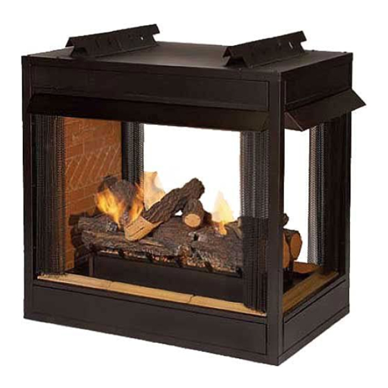
PREMIUM UNIVERSAL FIREBOX FOR
ALL VENT-FREE LOG SETS
SEE-THROUGH FIREBOX MODELS:
VFP36SB2E(L,F)-3
PENINSULA FIREBOX MODELS:
VFP36PB2E(L,F)-3
ANSI Z21.91 Ventless Fireplace Enclosures for use with any
ANSI Z21.11.2 Gas Fired Decorative Type Unvented Room
Heaters
DO NOT ATTEMPT TO MODIFY OR ALTER THE CONSTRUC-
TION OF THE FIREBOX OR ITS COMPONENTS. ANY MODI-
FICATION OR ALTERATION OF CONSTRUCTION MAY VOID
THE WARRANTY OF THIS FIREBOX.
CHILDREN AND ADULTS SHOULD BE ALERTED TO THE
HAZARDS OF HIGH SURFACE TEMPERATURE AND
SHOULD STAY AWAY TO AVOID BURNS OR CLOTHING IG-
NITION.
YOUNG CHILDREN SHOULD BE CAREFULLY SUPERVISED
WHEN THEY ARE IN THE SAME ROOM AS THE FIREBOX.
INSTALLATION INSTRUCTIONS
AND OWNER'S MANUAL
GAS-FIRED
WARNING: Improper installation, adjustment, alteration,
service or maintenance can cause injury or property dam-
age. Refer to this manual. For assistance or additional infor-
mation, consult a qualified installer, service agency or the
gas supplier.
Carefully review the instructions supplied with the decora-
tive type unvented room heater for the minimum fireplace
size requirement.
DO NOT INSTALL A VENT-FREE LOG SET IN THIS FIREBOX,
UNLESS THIS FIREBOX MEETS THE MINIMUM DIMENSIONS
REQUIRED FOR THE INSTALLATION.
FOR USE ONLY WITH A LISTED GAS-FIRED UNVENTED
DECORATIVE ROOM HEATER NOT TO EXCEED
40,000 BTU/H.
DO NOT BUILD A WOOD FIRE.
Installer:
Leave this manual with the appliance.
Consumer:
Retain this manual for future reference.
WARNING: If the information in these instructions are
not followed exactly, a fire or explosion may result caus-
ing property damage, personal injury or loss of life.
— Do not store or use gasoline or other flammable va-
pors and liquids in the vicinity of this or any other ap-
pliance.
— WHAT TO DO IF YOU SMELL GAS
•
Do not try to light any appliance.
•
Do not touch any electrical switch; do not use any
phone in your building.
•
Immediately call your gas supplier from a neigh-
bor's phone. Follow the gas supplier's instruc-
tions.
•
If you cannot reach your gas supplier, call the fire
department.
— Installation and service must be performed by a quali-
fied installer, service agency or the gas supplier.
Page 1
Advertisement
Table of Contents

Related Manuals for Empire VFP36SB2E(L,F)-3


Summary of Contents for Empire VFP36SB2E(L,F)-3
- Page 1 Refer to this manual. For assistance or additional infor- mation, consult a qualified installer, service agency or the gas supplier. SEE-THROUGH FIREBOX MODELS: VFP36SB2E(L,F)-3 Carefully review the instructions supplied with the decora- tive type unvented room heater for the minimum fireplace size requirement.
-
Page 2: Table Of Contents
TABLE OF CONTENTS SECTION PAGE Important Safety Information .................. 3 Introduction ......................3 Clearances ......................4 - 5 Firebox Installation Instructions ................6 - 8 Installing Hood ....................8 - 9 Gas Line Connection ....................9 Wiring Instructions for Installing a Dual Switch / Receptacle ........ 10 LK2 Accent Light Accessory .................. -
Page 3: Important Safety Information
This Empire Comfort Systems Inc. firebox and its - Installation and/or use of any component part components have been tested and will operate safely... -
Page 4: Clearances
CLEARANCES Sidewall Clearances: The clearance from the inside of the firebox Combustible material clearance from front of firebox: 36" to perpendicular combustible side wall should not be less than 1 minimum 3/4". See Figures 1a and 1b. Firebox Side and Back Clearances: The firebox outer casing side(s) require a minimum 1/2" clearance to combustibles. Top Framing and Finishing: Combustible framing may rest on top of standoffs. Combustible finishing materials may extend to the top standoff screws on the front edge of the top outer wrap. - Page 5 CLEARANCES Ceiling Clearances: The ceiling height should not be less than 42" Mantel Clearances: Vent free firebox models must use the hood from the top of the hood. See Figures 3a and 3b. supplied with the firebox, or one of the optional hood kits available for each model. If a combustible mantel is installed, it must meet the clearance requirements detailed below. CEILING Grate Clearance: The minimum clearance between the front legs of the grate and the front edges of the firebox is 1 1/2".
-
Page 6: Firebox Installation Instructions
FIREBOX INSTALLATION INSTRUCTIONS Note: On Peninsula models, a maximum weight of 250 lbs. is Any vent-free Gas Log Heater must be “For use with approved ANSI Z21.11.2 unvented room heater.” recommended when construction materials are supported by the top standoff spacers. Follow and complete the installation instructions of the gas log set and the requirements of this firebox. - Page 7 FIREBOX INSTALLATION INSTRUCTIONS (continued) 2 9/16” 2 9/16” 2 9/16” SEE THRU PENINSULA LOUVERED LOUVERED FLUSH FLUSH LOUVERED PANELS FLUSH PANELS VFP36SB VFP36PB VFP36SB VFP36PB 38 1/8" 38 1/8" 38 1/8" 38 1/8" 39" 39" 39" 39" 24" 24" 24" 24"...
-
Page 8: Installing Hood
FIREBOX INSTALLATION INSTRUCTIONS (continued) Locating Firebox Place firebox in framed opening. Attach the framing brackets to the firebox and secure firebox to framing. Different hole locations can be used for finishing materials with thicknesses of 3/8", 1/2" and 3/4". Secure the brackets with screws provided using two per framing bracket. See Figure 7. Framing brackets should fit directly against framing material. Use at least one nail or screw per bracket to secure in place. IMPORTANT! Check squareness of the firebox prior to securing to FIREBOX OPENING framed opening. -
Page 9: Gas Line Connection
INSTALLING HOOD (continued) Extended Hoods Finishing All joints (top, bottom and sides), where the wall or decorative If your non-combustible facing material is over 1" in thickness and facing material meets the firebox surround should be sealed with a will be used to finish this firebox, extended hoods are available that non-combustible material. will extend out 2" farther into the room. Extended hoods are not available for the peninsula open ends. -
Page 10: Wiring Instructions For Installing A Dual Switch / Receptacle
WIRING INSTRUCTIONS FOR INSTALLING A DUAL SWITCH / RECEPTACLE In order to install both the optional Blower and Accent Light acces- speed control, the SCV1 Variable Speed Control Kit should be in- sories, it will be necessary to install the junction box so that the stalled to control the power to one side of the duplex receptacle. -
Page 11: Optional Single Speed Blower Installation Instructions
OPTIONAL SINGLE SPEED BLOWER INSTALLATION INSTRUCTIONS Attention: If installed, do not damage gas inlet supply line when Attention: Install blower assembly before connecting blower assembly is inserted into firebox. In some cases, removal gas inlet supply line. of the gas inlet supply line may be necessary. Wiring 3. Determine which type of firebox you have prior to installation. The appliance, when installed, must be electrically grounded in See Figures 13 and 14. - Page 12 4. Insert blower assembly into interior, bottom of firebox. Posi- WIRES tion blower assembly so that you align the notch on back of FROM FAN CONTROL blower assembly with the center screw on side/end panel, SWITCH then push the blower assembly against firebox outer panel. The blower wheel must be centered with the side/end wall of the firebox. The magnets on the back and bottom of blower assembly will sufficiently hold blower assembly in place. See Figure 16.
-
Page 13: Maintenance
Blower Motor 110 VOLT AC The blower motor does not have oiling holes. Do not attempt to oil JUNCTION BOX the blower motor. FAN/MOTOR ASSEMBLY Blower Wheels The blower wheels will collect lint and could require periodic clean- ing. If the air output decreases or the noise level increases, it indi- cates a dirty blower wheel. -
Page 14: Parts List
PARTS LIST Part Number Index Description Number VFP36SB2EL VFP36SB2EF VFP36PB2EL VFP36PB2EF FIREBOX ASSEMBLY 17149 17149 17149 17149 TOP STANDOFF R9655 R9655 R9655 R9655 INSULATION - TOP 24067 24067 24067 24067 INSULATION SUPPORT R7052 R7052 R7052 R7052 SCREEN ROD R9633 R9633 SCREEN ROD R9631 R9631... -
Page 15: See-Through Firebox Parts View
SEE-THROUGH FIREBOX PARTS VIEW 27451-5-0614 Page 15... -
Page 16: Peninsula Firebox Parts View
PENINSULA FIREBOX PARTS VIEW Page 16 27451-6-0614... -
Page 17: Accessories
ACCESSORIES Accessory Description Model Numbers Fan Kit Designed to provide forced air flow. FBB5 Note: For use with louvered or flush panel models. Variable Speed Control Kit Wall mounted variable speed control for use with SCV-1 FBB5 blower Frame Kits Standard 3-Piece Frame Kits Black, Brass, Stainless Steel, or Hammered Pewter For use with See-Through models: VFP36SB2E(L,F) ONLY Contact dealer for all available Extruded Aluminum Frame Kits... - Page 18 ACCESSORIES (continued) Extended 4" Hoods Extended hoods that extend out 2" farther than the stan- dard hoods, to accommodate thicker surround materials. Contact dealer for all available Available as optional kits in Black, Brass, Hammered optional hood accessories Pewter, and Stainless Steel finishes. Note: Not available for Peninsula open ends. Louvers Styles include Slat, Mission, Arch, and Leaf Patterns.
-
Page 19: Master Parts Distributor List
MASTER PARTS DISTRIBUTOR LIST To Order Parts Under Warranty, please contact your local Empire dealer. See the dealer locator at www.empirecomfort. com. To provide warranty service, your dealer will need your name and address, purchase date and serial number, and the nature of the problem with the unit. -
Page 20: Warranty
WARRANTY Empire Comfort Systems Inc. warranties this hearth product to be free from defects at the time of purchase and for the periods speci- fied below. Hearth products must be installed by a qualified technician and must be maintained and operated safely, in accordance with the instructions in the owner’s manual. This warranty applies to the original purchaser only and is not transferable. All warranty repairs must be accomplished by a qualified gas appliance technician.
Need help?
Do you have a question about the VFP36SB2E(L,F)-3 and is the answer not in the manual?
Questions and answers