Table of Contents
Advertisement
Change for Life
GREE ELECTRIC APPLIANCES,INC.OF ZHUHAI
Service Manual
MODELS: GWH(09)MA-K3DNA2B/I
GWH(12)MB-K3DNA2B/I
GWH(18)MC-K3DNA2B/I
GWH(07)MA-K3DNA3B/I
GWH(09)MA-K3DNA3B/I
GWH(12)MB-K3DNA3B/I
GWH(18)MC-K3DNA3B/I
GWH(09)MA-K3DNB8B/I
GWH(12)MB-K3DNB8B/I
GWH(07)MA-K3DNC5B/I
GWH(09)MA-K3DNC5B/I
GWH(12)MB-K3DNC5B/I
GWH(18)MC-K3DNC5B/I
GWH(07)MA-K3DNB8B/I(Cold plasma)
GWH(09)MA-K3DNB8B/I(Cold plasma)
GWH(12)MB-K3DNB8B/I(Cold plasma)
GWH(18)MC-K3DNB8B/I(Cold plasma)
Advertisement
Table of Contents

Related Manuals for Gree GWH(09)MA-K3DNA2B


Summary of Contents for Gree GWH(09)MA-K3DNA2B
-
Page 1: Service Manual
Change for Life Service Manual MODELS: GWH(09)MA-K3DNA2B/I GWH(12)MB-K3DNA2B/I GWH(18)MC-K3DNA2B/I GWH(07)MA-K3DNA3B/I GWH(09)MA-K3DNA3B/I GWH(12)MB-K3DNA3B/I GWH(18)MC-K3DNA3B/I GWH(09)MA-K3DNB8B/I GWH(12)MB-K3DNB8B/I GWH(07)MA-K3DNC5B/I GWH(09)MA-K3DNC5B/I GWH(12)MB-K3DNC5B/I GWH(18)MC-K3DNC5B/I GWH(07)MA-K3DNB8B/I(Cold plasma) GWH(09)MA-K3DNB8B/I(Cold plasma) GWH(12)MB-K3DNB8B/I(Cold plasma) GWH(18)MC-K3DNB8B/I(Cold plasma) GREE ELECTRIC APPLIANCES,INC.OF ZHUHAI... -
Page 2: Table Of Contents
Table Contents Summary and Features ..................1 Part 1 Safety Precautions ...................2 Part 2 Specifications ..................... 3 2.1 Unit Specifications ....................3 2.2 Capacity Variation Ratio According to Temperature..........4 Part 3 Construction Views ..................5 Part 4 Refrigerant System Diagram ..............6 Part 5 Schematic Diagram ..................7 5.1 Electrical Data......................7 5.2 Electrical Wiring.......................7... -
Page 3: Summary And Features
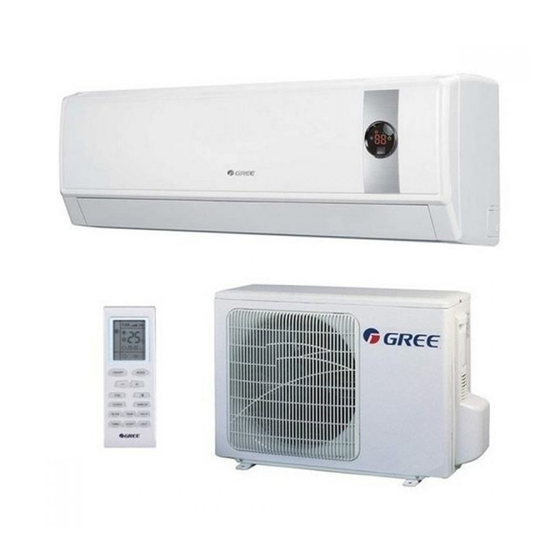
Summary and features Summary and features Indoor Unit GWH(09)MA-K3DNA2B/I GWH(12)MB-K3DNA2B/I GWH(18)MC-K3DNA2B/I GWH(07)MA-K3DNA3B/I GWH(09)MA-K3DNA3B/I GWH(12)MB-K3DNA3B/I GWH(18)MC-K3DNA3B/I GWH(09)MA-K3DNB8B/I GWH(12)MB-K3DNB8B/I GWH(07)MA-K3DNB8B/I(Cold plasma) GWH(09)MA-K3DNB8B/I(Cold plasma) GWH(12)MB-K3DNB8B/I(Cold plasma) GWH(18)MC-K3DNB8B/I(Cold plasma) GWH(07)MA-K3DNC5B/I GWH(09)MA-K3DNC5B/I GWH(12)MB-K3DNC5B/I GWH(18)MC-K3DNC5B/I Remote Controller YT1F MODE I FEEL TIMER CLOCK TIMER X-FAN TEMP... -
Page 4: Part 1 Safety Precautions
Safety Precautions 1.Safety Precautions Installing, starting up, and servicing air conditioner can be Make sure the outdoor unit is installed on a stable, level hazardous due to system pressure, electrical components, surface with no accumulation of snow, leaves, or trash and equipment location, etc. -
Page 5: Part 2 Specifications
Specifications Specifications 2.1 Unit Specifications GWH(09)MA-K3DNA2B/I GWH(12)MB-K3DNA2B/I GWH(18)MC-K3DNA2B/I GWH(07)MA-K3DNA3B/I GWH(09)MA-K3DNA3B/I GWH(12)MB-K3DNA3B/I GWH(18)MC-K3DNA3B/I GWH(07)MA-K3DNC5B/I GWH(09)MA-K3DNB8B/I GWH(12)MB-K3DNB8B/I Model GWH(18)MC-K3DNC5B/I GWH(07)MA- GWH(09)MA-K3DNC5B/I GWH(12)MB-K3DNC5B/I GWH(18)MC- K3DNB8B/I(Cold plasma) GWH(09)MA- GWH(12)MB- K3DNB8B/I(Cold plasma) K3DNB8B/I(Cold plasma) K3DNB8B/I(Cold plasma) CB181N02700 CB181N02800 CB181N02900 CB171N0400 CB171N0340 CB171N0350 CB171N0360 Product Code... -
Page 6: Capacity Variation Ratio According To Temperature
Specifications 2.2 Noise Criteria Curve Tables for Both Models Middle High Super High Indoor Fan Motor Rotating Speed... -
Page 7: Part 3 Construction Views
Constrction views 3. Construction Views 7K&09K Model(mm) 7K&09K... -
Page 8: Part 4 Refrigerant System Diagram
Refrigerant System Diagram 4. Refrigerant System Diagram Cooling & Heating Models outdoor indoor filter A heat exchanger filter outdoor heat exchanger 4-way valve B heat exchanger filter high pressure switch Note: Not available for 14K/18K model discharge silencer C heat exchanger discharge temperature sensor filter... -
Page 9: Part 5 Schematic Diagram
Schematic Diagram 5. Schematic Diagram 5.1 Electrical Data Meaning of marks Symbol Color symbol Symbol Color symbol WHITE BROWN YELLOW BLUE BLACK YEGN YELLOW GREEN VIOLET ORANGE PROTECTIVE EARTH OVERLOAD COMP COMPRESSOR 5.2 Electrical Wiring For 07/09/12K Unit ROOM TUBE MOTOR TEM.SENSOR TEM.SENSOR... - Page 10 Schematic Diagram For 18K Unit FAN MOTOR TUBE ROOM TEM.SENSOR TEM.SENSOR ROOM TUBE N(1) COM-OUT AC-L YEGN JUMP 4YEGN SWING-UD DISP1 DISP2 EVAPORATOR HEALTH-L HEALTH-N COOL PLASMA GENERATOR SWING RECEIVER AND MOTOR (optional) DISPLAY BOARD These circuit diagrams are subject to change without notice, please refer to the one supplied with the unit.
-
Page 11: Printed Circuit Board
Schematic Diagram 5.3 Printed Circuit Board For 07/09/12K Unit TOP VIEW Power supply live wire Indoor fan wire terminal Jumper cap terminal connector Power supply neutral wire indoor and outdoor unit Display panel terminal connector communication wire terminal Up & down swing control Indoor ambient temperature Fan capacitor terminal... - Page 12 Schematic Diagram TOP VIEW For 18K Unit Power supply live wire connector Power supply neutral wire connector Protective tube Fan capacitor PG motor connector Auto button Up & down swing connector PG motor fan feedback terminal Display panel connector Indoor and outdoor unit communication wire terminal Jumper cap terminal Indoor ambient temperature...
-
Page 13: Part 6 Function And Control
Function and Control 6. Function and Control 6.1 Remote Control Operations ON/OFF Press it to start or stop operation. Press it to decrease temperature setting. Press it to increase temperature setting. Press it to set fan speed. MODE Press it to select operation mode (AUTO/COOL/DRY/FAN/HEAT). I FEEL Press it to set HE ALTH function Press it to set AIR function. -
Page 14: Digital Display
Function and Control SLEEP icon : is displayed by pressing the SLEEP button. Press this button again to clear the display. TEMP icon: Pressing TEMP button, (set temperature), (ambient temperature), (outdoor ambient temperature) and blank is displayed circularly. Up & down swing icon: is displayed when pressing the up &... -
Page 15: Timer Off
Function and Control I FEEL: Press this button to turn on I FEEL function. The unit automatically adjust temperature according to the sensed temperature. Press this button again to cancel I FEEL function. Press this button to set HEALTH function ON or OFF. After the unit is turned on, it defaults to HEALTH function ON. Press this button to select AIR function ON or OFF. -
Page 16: Replacement Of Batteries
Function and Control Combination of "+" and "-" buttons: About lock Press "+ " and "-" buttons simultaneously to lock or unlock the keypad. If the remote controller is locked, is displayed. In this case, pressing any button, blinks three times. Combination of "MODE"... -
Page 17: Description Of Each Control Operation
Function and Control 6.2 Description of Each Control Operation I. Basic Operation Mode 1. Cool; 2.Dry; 3.Heat; 4.Auto; 5.Fan II. Basic Functions Cooling Only (1) Under this mode, fan and swing run at preset status, the temperature setting range is 16-30 . indoor temperature---target temperature (2) Under malfunction for outdoor unit and protection stop, the indoor unit runs with the original status, and display malfunction. - Page 18 Function and Control III. Other Control 1. Buzzer The buzzer will give out a beep when the controller is energized, receiving signal from remote controller and auto button. 2. Auto Button Press this button once, it will operate in Auto mode, and indoor fan operates in Auto fan mode and swing. When the unit is on, pressing this button will turn off the unit.
- Page 19 Function and Control 2.3 Timer Change Timer On and Timer OFF can be set via remote ON/OFF button. Timer time can be reset and the system will operate according to the latest setting. When the unit is on and Timer On and Timer Off are both set, the system will operate according to the set state. When the timer off time is reached, the system will stop.
-
Page 20: Part 7 Installation Manual
Installation Manual 7. Installation Manual 7.1 Notices for Installation Caution 1.The unit should be installed only by authorized service center according to local or government regulations and in compliance with this manual. 2.Before installing, please contact with local authorized maintenance center. If the unit is not installed by the authorized service center, the malfunction may not be solved due to incovenient contact between the user and the service personnel. -
Page 21: Installation Drawing
Installation Manual 7.1.4 Earthing Requirements .Air conditioner is type I electric appliance. Please ensure that the unit is reliably earthed. 2.The yellow-green wire in air conditioner is the earthing wire which can not be used for other purposes. Improper earthing may cause electric shock. 3.The earth resistance should accord to the national criterion. -
Page 22: Install Indoor Unit
Installation Manual 7.3 Install Indoor Unit 7.3.1 Installation of Mounting Plate 07&09K UNIT: 12K UNIT: Wall Wall Wall Wall Wall Wall Left Right Left Right 18K UNIT: Wall Wall Wall Left Right 7.3.2 Drill Piping Hole Wall pipe Seal pad m being damaged n passing h the hole. -
Page 23: Check After Installation And Operation Test
Installation Manual NOTE: All wires between indoor and outdoor units must be connected by the qualified electric contractor. ● Electric wires must be connected correctly. Improper connection may cause malfunction. ● Tighten the terminal screws tightly. ● After tightening the screws, pull the wire sligltly to confirm whether it's firm or not. ●... -
Page 24: Installation And Maintenance Of Healthy Filter
Installation Manual 7.4.2 Operation Test 1.Before Operation Test (1)Do not switch on power before installation is finished completely. (2)Electric wiring must be connected correctly and securely. (3)Cut-off valves of the connection pipes should be opened. (4)All the impurities such as scraps and thrums must be cleared from the unit. 2.Operation Test Method (1)Switch on power and press "ON/OFF"?button on the remote controller to start operation. -
Page 25: Part 8 Exploded Views And Parts List
Exploded Views and Parts list 8. Exploded Views and Parts List Models: GWH(07)MA-K3DNA3B/I GWH(07)MA-K3DNC5B/I GWH(09)MA-K3DNA2B/I GWH(09)MA-K3DNA3B/I GWH(09)MA-K3DNB8B/I GWH(09)MA-K3DNC5B/I... - Page 26 Exploded Views and Parts list Part Code Description GWH(07)MA-K3DNA3B/I GWH(07)MA-K3DNC5B/I Product Code CB171N0400 CB179N00900 Receiver Window 20192229 22432194 Front Panel Assy 20012241 20012611 Filter Sub-Assy 11122081 11122081 Screw Cover 24252016 24252016 Front Case 20012120C 20012179C Air Louver 2 10512114 10512114 Air Louver 1 10512113 10512113...
- Page 27 Exploded Views and Parts list Part Code Description GWH(09)MA-K3DNA3B/I GWH(09)MA-K3DNA2B/I Product Code CB171N0340 CB181N02700 Receiver Window 20192229 20192229 Front Panel Assy 20012121S 20012142S Filter Sub-Assy 11122081 11122081 Screw Cover 24252016 24252016 Front Case 20012120C 20012120C Air Louver 2 10512114 10512114...
- Page 28 Exploded Views and Parts list Part Code Description GWH(09)MA-K3DNB8B/I GWH(09)MA-K3DNC5B/I Product Code CB174N01900 CB179N01000 Receiver Window 22432194 Front Panel 2001232601 20012586S Filter Sub-Assy 11122081 11122081 Screw Cover 24252016 24252016 Front Case 20012120C 20012179C Air Louver 2 10512114 10512114 Air Louver 1 10512113 10512113 Helicoid Tongue...
- Page 29 Exploded Views and Parts list Model: GWH(12)MB-K3DNA2B/I GWH(12)MB-K3DNA3B/I GWH(12)MB-K3DNB8B/I GWH(12)MB-K3DNC5B/I...
- Page 30 Exploded Views and Parts list Part Code Description GWH(12)MB-K3DNA3B/I GWH(12)MB-K3DNA2B/I Product Code CB171N0350 CB181N02800 Receiver Window 22432230 22432230 Front panel B1 20012122S 20012150S Filter Sub-Assy 1112220403 1112220403 Screw Cover 24252016 24252016 Front Case Sub-Assy 2001213908 2001213908 Air Louver 2 10512155 10512155 Air Louver 1 10512156...
- Page 31 Exploded Views and Parts list Part Code Description GWH(12)MB-K3DNB8B/I GWH(12)MB-K3DNC5B/I Product Code CB174N02000 CB179N01100 Receiver Window 22432230 22432230 Front Panel 11 20012204 20012614 Filter Sub-Assy 1112220403 1112220403 Screw Cover 24252016 24252016 Front Case Sub-assy 2001213908 2001213915 Air Louver 2 10512155 10512155 Air Louver 1 10512156...
- Page 32 Exploded Views and Parts list Model: GWH(18)MC-K3DNA2B/I GWH(18)MC-K3DNA3B/I GWH(18)MC-K3DNC5B/I...
- Page 33 Exploded Views and Parts list Part Code Description GWH(18)MC-K3DNA3B/I GWH(18)MC-K3DNA2B/I Product Code CB171N0360 CB181N02900 Receiver Window 22432173 22432173 Front Panel Assy 20012260 20012142S Filter Sub-Assy 1112208901 1112208901 Screw Cover 24252016 24252016 Baffle Plate 26112228 26112228 Front Case Sub-Assy 20012288 20012288 Air Louver 2 10512117 10512117...
- Page 34 Exploded Views and Parts list Part Code Description GWH(18)MC-K3DNC5B/I Product Code CB179N01200 Receiver Window 22432194 Front Panel Assy 20012583 Filter Sub-Assy 1112208901 Screw Cover 24252016 Baffle Plate 26112228 Front Case Sub-assy 20012766 Air Louver 2 10512117 Air Louver 1 10512116 Helicoid Tongue 26112238 Left Axile Bush...
- Page 35 Exploded Views and Parts list Model: GWH(07)MA-K3DNB8B/I(Cold plasma) GWH(09)MA-K3DNB8B/I(Cold plasma)
- Page 36 Exploded Views and Parts list Part Code Description GWH(07)MA-K3DNB8B/I(Cold GWH(09)MA-K3DNB8B/I(Cold plasma) plasma) Product Code CB174N02100 CB174N01901 Receiver Window Front Panel G1 2001232609 2001232609 Filter Sub-Assy 11122081 11122081 Screw Cover 24252016 24252016 Front Case 20012120C 20012120C Air Louver 2 10512114 10512114 Air Louver 1 10512113 10512113...
- Page 37 Exploded Views and Parts list Model: GWH(12)MB-K3DNB8B/I(Cold plasma)
- Page 38 Exploded Views and Parts list Part Code Description GWH(12)MB-K3DNB8B/I(Cold plasma) Product Code CB174N02001 Receiver Window Front Panel 11 2001220409 Filter Sub-Assy 1112220403 Screw Cover 24252016 Front Case Sub-assy 2001213908 Air Louver 2 10512155 Air Louver 1 10512156 Helicoid Tongue 26112163 Left Axile Bush 10512037 Rear Case assy...
- Page 39 Exploded Views and Parts list Model: GWH(18)MC-K3DNB8B/I(Cold plasma)
- Page 40 Exploded Views and Parts list Part Code Description GWH(18)MC-K3DNB8B/I(Cold plasma) Product Code CB174N02200 Receiver Window Front Panel B8 20012485 Filter Sub-Assy 1112208901 Screw Cover 24252016 Baffle Plate 26112228 Front Case Sub-assy 20012288 Air Louver 2 10512117 Air Louver 1 10512116 Helicoid Tongue 26112238 Left Axile Bush...
-
Page 41: Part 9 Troubleshooting
Troubleshooting 9. Troubleshooting 9.1 Malfunction Display of Indoor Unit 1. Malfunction display requirement When there are several malfunctions, they will be displayed circularly. 2. Malfunction display method (1) Hardware malfunction: immediate display; refer to “malfunction display table”; (2) Operation state: immediate display; refer to “malfunction display table”; (3) Other malfunctions: it is displayed after the compressor stops for 200s;... - Page 42 Troubleshooting blink Module temperature protection 19 times blink Charging malfunction of capacitor 17 times High pressure protection of system blink once Overload protection of compressor blink 3 times Wrong connection for communication wire or malfunction of expansion valve (free match) Wrong connection for communication wire or malfunction detection status of expansion valve (free match) Mode shock...
-
Page 43: How To Check Simply The Main Part
Troubleshooting 9.2 How to Check Simply the Main Part 9.2.1 F1/F2 malfunction Start Is the wiring terminal between temperature sensor and the controller loosened or poo rly contacted? Insert the temperature sensor tightly Malfunction is eliminated. Is there short circuit due to tri-pover of the pa rts? Make the parts upright Malfunction is... - Page 44 Troubleshooting 9.2.2 H6 malfunction Possible causes:1.Fan motor is locked; 2.The feedback terminal of PG motor is not connected tightly; 3.The control terminal of PG motor is not connected tightly; 4.Motor is damaged; 5.Malfunction of the rotation speed detection circuit of the mainboard.See the flow chart below: “...
- Page 45 Troubleshooting 9.2.3 C5 malfunction Possible causes:1.There is no jumper cap on the controller;2.Jumper cap is not inserted properly and tightly;3.Jumper cap is damaged;4. Controller is damaged.See the flow chart below: C5 is displayed on the unit. Install a matching Is there jumper cap on jumper cap .
- Page 46 Troubleshooting 9.2.4 U8 malfunction Possible causes; 1.The controller diagnoses incorrectly due to instant energization after de-energized while the capacitor discharges slowly; 2.Malfunction of the zero-cross detection circuit of the mainboard. See the flow chart below: “ U8 ” is displayed on the unit .
- Page 47 Troubleshooting 9.2.5 E6 malfunction Inspection Check if connection wire between indoor and outdoor units and wire inside the unit are connected well. Check if mainboard of indoor or outdoor unit is damaged Flowchart Communication malfunction of some indoor units De-energize the unit and check if the connecting wire of indoor and outdoor unit and wiring of electric box are correct.
- Page 48 Troubleshooting Communication malfunction of all indoor units De-energize the unit and check if the connecting wire of indoor and outdoor unit and wiring of electric box are correct. Connect wires Is wire connected Is malfunction according to the correctly removed wiring diagram De-energize the unit.
-
Page 49: Removal Procedure
Removal Procedure 10. Removal Procedure Warning Be sure to wait for a minimum of 10 minutes after turning off all power supplies before disassembly. Note:Take A2 front panel for example. 1.Remove the filter Open the panel. panel Loosen the clasp of the filter. clasp Push the filter inward and then raise it to remove it. -
Page 50: Part10 Removal Procedure
Removal Procedure Bend the horizontal louver slightly to remove it. horizon- tal louver 3.Remove front panel Slide the rotor shaft out of the groove. Remove the front panel. rotor shaft front panel 4.Remove electric box cover 2 Remove the screws fixing the elec- tric box cover 2. - Page 51 Removal Procedure electric box cover Remove the electric box cover2. 5.Remove front case Open the screw cap on the front case. Remove the screws fixing the front case. screws clasps Loosen the left, middle and right clasps. left middle f r o n t right case Remove the front case.
- Page 52 Removal Procedure 6.Remove vertical louver Loosen the clasps connecting vertical louver with bottom case. clasps Remove the vertical louver. vertical louver 7.Remove electric box Heat exchanger thermistor Disconnect the indoor pipe tempera- ture sensor. screw Remove the screw of the electric box. screws Ground Wire Remove the screws at the joint of...
- Page 53 Removal Procedure Remove the clasp connecting elec- tric box cover and electric box. Re- move electric box cover. clasp fan motor signal wire Disconnect the connecting wire of the motor. Disconnect the connecting wire of the step motor. connector of step motor Remove the screw fixing the display.
- Page 54 Removal Procedure 8.Remove pipe connecting clamp Pipe Clamp Auxiliary Piping screw Remove the screw fixing the pipe connecting clamp. Pipe Clamp Remove the pipe connecting clamp. 9.Remove the evaporator Remove the 3 screws at the joint of the evaporator and bottom case. screws Auxiliary Piping Adjust the pipe of evaporator.
- Page 55 Removal Procedure Heat Remove the evaporator. Exchanger 10.Remove cross flow blade and motor Step Motor Remove the screws fixing the step motor. Remove the step motor. Motor Press Plate Remove the screws fixing the press plate of the motor. Remove the motor. Cross Flow Fan Fan Motor Remove cross flow blade and motor.
- Page 56 Removal Procedure O-Gasket sub-assy of Remove ring of bearing. Bearing Ring of Bearing Remove the screws at the joint of cross flow blade and motor. Remove Cross Flow Fan the motor. Fan Motor...
- Page 57 Add: West Jinji Rd, Qianshan, Zhuhai, Guangdong, China, 519070 Tel: (+86-756) 8522218 Fax: (+86-756) 8669426 E-mail: gree@gree.com.cn www.gree.com For continuous improvement in the products, Gree reserves the right to modidy the product specification and appearance in this manual without notice and without incurring any obligations.
Need help?
Do you have a question about the GWH(09)MA-K3DNA2B and is the answer not in the manual?
Questions and answers