Table of Contents
Advertisement
S/M No. :
Service Manual
Microwave Oven
Model: KOC-9Q0T
✔
Caution
: In this Manual, some parts can be changed for improving,
their performance without notice in the parts list. So, if you
need the latest parts information, please refer to PPL(Parts
Price List) in Service Information Center (http://svc.dwe.co.kr).
OC9Q0T7S001
Aug. 2008
Advertisement
Table of Contents

Related Manuals for Daewoo KOC-9Q0T


Summary of Contents for Daewoo KOC-9Q0T
-
Page 1: Microwave Oven
S/M No. : OC9Q0T7S001 Service Manual Microwave Oven Model: KOC-9Q0T ✔ Caution : In this Manual, some parts can be changed for improving, their performance without notice in the parts list. So, if you need the latest parts information, please refer to PPL(Parts Price List) in Service Information Center (http://svc.dwe.co.kr). -
Page 2: Table Of Contents
PRECAUTIONS TO BE OBSERVED BEFORE AND DURING SERVICING TO AVOID POSSIBLE EXPOSURE TO EXCESSIVE MICROWAVE ENERGY (a) Do not operate or allow the oven to be operated with the door open. (b) Make the following safety checks on all ovens to be serviced before activating the magnetron or other microwave source, and make repairs if necessary: (1) Interlock operation, (2) Proper door closing, (3) Seal and sealing surfaces (arcing, wear, and other damage), (4) Damage to or loosening of hinges and latches (5) Evidence of dropping or abuse. -
Page 3: Safety And Precautions
1. SAFETY AND PRECAUTIONS 1. FOR SAFE OPERATION Damage that allows the microwave energy (that cooks or heats the food) to escape will result in poor cooking and may cause serious bodily injury to the operator. IF ANY OF THE FOLLOWING CONDITIONS EXIST, OPERATOR MUST NOT USE THE APPLIANCE. (Only a trained service personnel should make repairs.) (1) A broken door hinge. -
Page 4: Specifications
2. SPECIFICATIONS MODEL KOC-9Q0T7S POWER SUPPLY 230V~50Hz, SINGLE PHASE WITH EARTHING MICROWAVE 1400W POWER GRILL 1250W CONSUMPTION CONVECTION 1250W COMBINATION 2700W MICROWAVE ENERGY OUTPUT 900W (IEC 705) MICROWAVE FREQUENCY 2450MHz OUTSIDE DIMENSIONS (W X D X H) 513X401X311mm(20.2X15.8X12.2 in.) CAVITY DIMENSIONS (W X D X H) 354X341X231mm(13.9X13.4X9.1 in.) NET WEIGHT Approx. -
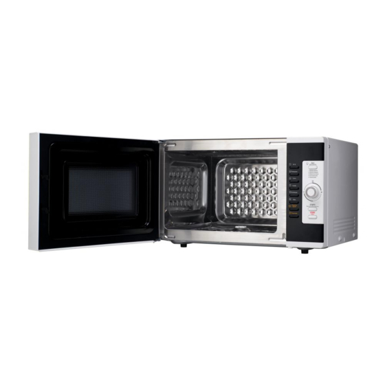
Page 5: External View
3. EXTERNAL VIEW 1. OUTER DIMENSION... -
Page 6: Feature Diagram
2. FEATURE DIAGRAM 11. DOOR HOOK Hook automatically locks and holds the door when the door shuts. If the door opens while the oven is operating, the oven will stop operating immediately. 12. DOOR SEAL Door seal prevents the microwave leakage from the oven cavity. 13. -
Page 7: Installation
• This appliance is supplied with cable of special type, which, if damaged, must be repaired with cable of same type. Such a cable can be purchased from DAEWOO and must be installed by a Qualified Person. 6. Examine the oven after unpacking for any damage such as: A misaligned door, broken door or a dent in cavity. -
Page 8: Control Panel
5. CONTROL PANEL 1 Display : Cooking time, power level, program indicators and present time are displayed. MW ( ): When blinking, the oven is operating in MICROWAVE COOK mode. Grill ( ): When blinking, the oven is operating in GRILL mode. -
Page 9: Disassembly And Assembly
6. DISASSEMBLY AND ASSEMBLY - Cautions to be observed when trouble shooting. Unlike many other appliances, the microwave oven is high-voltage, high-current equipment. It is completely safety during normal operation. However, carelessness in servicing the oven can result in an electric shock or possible danger from a short circuit. - Page 10 1. To remove cabinet 1) Remove five screws on cabinet back. 2) Push the cabinet backward. 2. To remove door assembly 1) Remove two screws which secure the stopper hinge top. 2) Remove the door assembly from top plate of cavity. 3) Reverse the above for assembly.
- Page 11 Caution In this Manual, some parts can be changed for improving, their performance without notice in the parts list. So, if you need the latest parts information, please refer to PPL(Parts Price List) in Service Information Center (http://svc.dwe.co.kr). 3. To remove door parts. REF NO.
- Page 12 4. Method to reduce the gap between the door seal and the oven front surface. (1) To reduce gap located on part ‘A’. • Loosen two screws on stopper hinge top, and then push the door to contact the door seal to oven front surface. •...
- Page 13 Caution In this Manual, some parts can be changed for improving, their performance without notice in the parts list. So, if you need the latest parts information, please refer to PPL(Parts Price List) in Service Information Center (http://svc.dwe.co.kr). 5. To remove control panel parts. B05 B03 B04 B06 REF NO.
- Page 14 6. To remove high voltage capacitor. 1) Remove a screw which secure the grounding ring terminal of the H.V. diode and the capacitor holder. 2) Remove the H.V. diode from the capacitor holder. 3) Reverse the above steps for reassembly. High voltage circuit wiring 7.
- Page 15 8. To remove wind guide assembly. 1) Remove a screw for earthing. 2) Remove the noise filter from the wind guide. 3) Remove a screw which secure the wind guide assembly. 4) Draw forward the wind guide assembly. 5) Pull the fan from the motor shaft. 6) Remove two screws which secure the motor shaded pole.
- Page 16 Caution In this Manual, some parts can be changed for improving, their performance without notice in the parts list. So, if you need the latest parts information, please refer to PPL(Parts Price List) in Service Information Center (http://svc.dwe.co.kr). 10. To remove fan convection assembly parts. C04 C05 REF NO.
- Page 17 Caution In this Manual, some parts can be changed for improving, their performance without notice in the parts list. So, if you need the latest parts information, please refer to PPL(Parts Price List) in Service Information Center (http://svc.dwe.co.kr). 11. To remove top heater assembly parts. REF NO.
- Page 18 Caution In this Manual, some parts can be changed for improving, their performance without notice in the parts list. So, if you need the latest parts information, please refer to PPL(Parts Price List) in Service Information Center (http://svc.dwe.co.kr). 12. To remove guide air assembly parts. REF NO.
-
Page 19: Interlock Mechanism And Adjustment
7. INTERLOCK MECHANISM AND ADJUSTMENT The door lock mechanism is a device which has been specially designed to completely eliminate microwave radiation when the door is opened during operation, and thus to perfectly prevent the danger resulting from the leakage of microwave. (1) Primary interlock switch When the door is closed, the hook locks the oven door. -
Page 20: Trouble Shooting Guide
8. TROUBLE SHOOTING GUIDE Following the procedure below to check if the oven is defective or not. 1) Check grounding before trouble checking. 2) Be careful of the high voltage circuit. 3) Discharge the high voltage capacitor. 4) When checking the continuity of the switches, fuse or high voltage tranformer, disconnect one load wire from these parts and check continuity with the AC plug removed. - Page 21 CONDITION CHECK RESULT CAUSE REMEDY Defective Outlet has Check continuity of Replace continuity magnetron. proper magnetron voltage fuse does not blow? Check continuity of noise filter Defective line Replace continuity board filter board Open power Check continuity of Replace continuity supply cord power supply cord Defective touch...
- Page 22 TROUBLE 3) No microwave oscillation even though fan motor rotates. CONDITION CHECK RESULT CAUSE REMEDY Check continuity of Replace Defective continuity high voltage fuse microwave high voltage oscillation fuse No microwave oscillation Continuity Check continuity of Defective high voltage capacitor terminals high voltage with wires removed transformer...
- Page 23 (TROUBLE 4) Top heater (main) is not heated; food will not become hot. CONDITION CHECK RESULT CAUSE REMEDY Malfunction of Adjust or Check continuity of Main heater is primary Interlock replace continuity primary interlock switch not heated. switch Adjust or Check continuity of Malfunction of replace...
- Page 24 (TROUBLE 6) The following visual conditions inditions indicate a probable defective touch control Circuit or button P.C.B. assembly 1. Incomplete segments. 1) segment missing 2) partial segments missing 3) digit flickering other than normal fluorescent slight flickering 2. A distinct change in the brightness of one or more numbers exists in the display.
-
Page 25: Mesurement And Test
9. MEASUREMENT AND TEST 1. MEASUREMENT OF THE MICROWAVE POWER OUTPUT Microwave output power can be checked by indirectly measuring the temperature rise of a certain amount of water exposed to the microwave as directed below. PROCEDURE 1. A cylindrical container of borosilicate glass is used for the test. It has a maximum thickness of 3mm, an external diameter of approximately 190mm and a height of approximately 90mm. -
Page 26: Microwave Radiation Test
2. MICROWAVE RADIATION TEST WARNING 1. Make sure to check the microwave leakage before and after repair of adjustment. 2. Always start measuring of an unknown field to assure safety for operating personnel from microwave energy. 3. Do not place your hands into any suspected microwave radiation field unless the safe density level is known. 4. -
Page 27: Component Test Procedure
3. COMPONENT TEST PROCEDURE • High voltage is present at the high voltage terminal of the high voltage transformer during any cooking cycle. • It is neither necessary nor advisable to attempt measurement of the high voltage. • Before touching any oven components or wiring, always unplug the oven from its power source and discharge the capacitor. -
Page 28: Component Action
4. COMPONENT ACTION MAGNE- MAIN CONVEC- COOKING MODE TRON HEATER HEATER TION FAN GRILL MANUAL MODE COMBI CONVECTION ROAST PORK ROAST BEEF AUTO ROAST CHICKEN MODE BAKED FISH FRESH VEGETABLES DEFROST STEAM CLEANING WARM... -
Page 29: Wiring Diagram
10. WIRING DIAGRAM... -
Page 30: Exploded View And Parts List
11. EXPLODED VIEW AND PARTS LIST 1. DOOR ASSEMBLY Refer to 6. Disassembly and assembly. 2. CONTROL PANEL ASSEMBLY Refer to 6. Disassembly and assembly. 3. TOTAL ASSEMBLY... - Page 31 Caution In this Manual, some parts can be changed for improving, their performance without notice in the parts list. So, if you need the latest parts information, please refer to PPL(Parts Price List) in Service Information Center (http://svc.dwe.co.kr). PARTS CODE PARTS NAME PARTS DESCRIPTION QUANTITY...
- Page 32 Caution In this Manual, some parts can be changed for improving, their performance without notice in the parts list. So, if you need the latest parts information, please refer to PPL(Parts Price List) in Service Information Center (http://svc.dwe.co.kr). PARTS CODE PARTS NAME PARTS DESCRIPTION QUANTITY...
-
Page 33: Printed Circuit Board
12. PRINTED CIRCUIT BOARD CIRCUIT CHECK PROCEDURE 1. Low voltage transformer check The low voltage transformer is located on the P.C.B. Measuring condition: Input voltage: 230V / Frequency: 50Hz Terminal Voltage(load) Voltage(no load) 7-8-9 DC 13.5 V AC 37 V NOTE 1. - Page 34 MEASUREPOINT...
- Page 35 3. Case of no microwave oscillation 1) When touching M/W button, oven lamp turns on and Fan motor and turntable rotate, and cook indicator in display comes on. *Cause: RELAY 1 does not operate. (MAGNETRON) 23 P12 22 P13 (LAMP,TRAY,FAN) (CONV.FAN) STATE POINT A...
- Page 36 4. Case of no heating of top heater main. When touching GRILL or COMBI or CONVECTION button, oven lamp turns on and fan motor and turntable rotate, and cook indicator in display comes on. *Cause: RELAY 3 does not operate. 24 P11 (GRILL) STATE...
- Page 37 6. Case of no stopping of the count down timer When the door is opened during operation, the count down timer does not stop. Q6 A1266Y 1N4148 4.7K YW396-02V 104Z D.O.M SW - Check method POINT STATE DOOR OPEN OPEN +5V DC DOOR CLOSED CLOSE...
-
Page 38: Circuit Diagram
13. P.C.B. CIRCUIT DIAGRAM... - Page 39 PCB ASS’Y PART LIST LOCATION PART CODE NAME SPECIFICATION Q'TY 3515600100 BUZZER BM-20K CN5XB-102M C ARRAY 6P(5) 1000PF M 50V CCZF1H473Z C CERA 50V HIKF 0.047uF Z C4,C6 CCZB1H102K C CERA 102K 50V AXIAL C1~3,C5,C8,C9 CCZF1H104Z C CERA 50V HIKF 0.1uF Z CEXE1H100A C ELECTRO 50V RSS 10MF...
- Page 40 DAEWOO ELECTRONICS CORP. 686, AHYEON-DONG MAPO-GU SEOUL, KOREA C.P.O. BOX 8003 SEOUL, KOREA TELEX: DWELEC K28177-8 CABLE: “DAEWOOELEC” S/M NO. : PRINTED DATE: Aug. 2008...
- Page 41 ABOUT THIS MANUAL ABOUT THIS MANUAL " " # # $ $ # # % % & & ! ' ' ( ( ) ) * * + + # # " " ) ) , , ! ! # # & & ' ' - - ./ 012 345 6 78 9:;<...
Need help?
Do you have a question about the KOC-9Q0T and is the answer not in the manual?
Questions and answers