Emulex OneConnect OCe14000-Series Installation Manual
Hide thumbs
Also See for OneConnect OCe14000-Series:
- Installation manual (25 pages) ,
- Installation manual (23 pages)

Related Manuals for Emulex OneConnect OCe14000-Series


Summary of Contents for Emulex OneConnect OCe14000-Series
- Page 1 OneConnect ® OCe14000-Series Adapters Installation Manual P009818-03A Rev. A Connect • Monitor • Manage...
- Page 2 Information furnished by Emulex is believed to be accurate and reliable. However, no responsibility is assumed by Emulex for its use; or for any infringements of patents or other rights of third parties which may result from its use. No license is granted by implication or otherwise under any patent, copyright or related rights of Emulex.
-
Page 3: Table Of Contents
For All Other OCe14000-series Adapters .............23 Viewing the LEDs ..................23 5. References ..................26 Specifications ..................26 FCC and Regulatory Notices............... 27 Declarations of Conformity................ 29 Laser Safety Notice ................. 30 OneConnect OCe14000-Series Adapters Installation Manual P009818-03A Rev. A... -
Page 4: List Of Figures
Connecting a Fiber Optic Cable for the OCe14000-series -NM/-UM Adapters ..................21 Figure 4-1 OCe14101-NM/-NX, OCe14102-NM/-NX, and OCe14102-UX/-UM Adapter LED Indicators ................24 Figure 4-2 OCe14401-NX/-UX Adapter LED Indicators ..........24 Figure 4-3 OCe14102-NT and OCe14102-UT LED Indicators........25 Figure 4-4 OCe14104-NM/-UM LED Indicators............25 OneConnect OCe14000-Series Adapters Installation Manual P009818-03A Rev. A... -
Page 5: List Of Tables
OCe14101-NX, OCe14102-NX/-UX, and OCe14104-NX/-UX Cable and Connector Specifications..............17 Table 3-2 OCe14401-NX/-UX Cable and Connector Specifications......17 Table 3-3 OCe14101-NX, OCe14102-NX, and OCe14104-NX/-UX Adapter Emulex OneConnect Accessories ..............19 Table 3-4 OCe14401-NX/UX Adapter Emulex OneConnect Accessories .......19 Table 3-5 OCe14101-NM, OCe14102-NM/-UM, and OCe14104-NM/-UM Adapter Cable and Connector Specifications ............20... -
Page 6: Introduction
1. Introduction 1. Introduction ® ® This manual describes the following Emulex OneConnect OCe14000-series of multi-protocol Peripheral Component Interconnect Express (PCIe) adapters that provide Ethernet networking, RDMA over Converged Ethernet (RoCE), internet Small Computer System Interface (iSCSI) functionality, and Fibre Channel over Ethernet (FCoE) functionality for convergence of Fibre Channel (FC) traffic onto a Ethernet fabric. - Page 7 10GbE SFP+ fiber optic cable with LC connector RoCE OCe14104-UM 4x10GbE RoCE iSCSI FCoE OCe14401-NX 1x40GbE 40GbE QSFP+ Passive DAC Cable RoCE 40GbE QSFP+ Active DAC Cable OCe14401-UX 1x40GbE RoCE iSCSI FCoE OneConnect OCe14000-Series Adapters Installation Manual P009818-03A Rev. A...
-
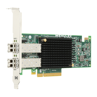
Page 8: Figure 1-1 Emulex Oce14102 Adapter
1. Introduction Note: Illustrations in this manual are only examples. The actual hardware may vary. Figure 1-1 Emulex OCe14102 Adapter Figure 1-2 Emulex OCe14102-NT/UT Adapter OneConnect OCe14000-Series Adapters Installation Manual P009818-03A Rev. A... -
Page 9: Features
1. Introduction Features Figure 1-3 Emulex OCe14401 Adapter All Emulex adapters support NIC single root I/O virtualization (SR-IOV) and are fully compliant to the PCIe Card Electromechanical (CEM) Specification Rev. 3.0/2.0/1.1. Converged network adapters (CNAs) combine two major functional components: a 10GbE networking media access control (MAC) sublayer and an FC I/O controller (IOC) to interface with a unified lossless Ethernet switch. -
Page 10: Oce14101 Adapters
1. Introduction Features Host interface support is provided through Emulex standard drivers Support for RoCE NIC operating system drivers (Windows Server and Linux OFED) As supported, a comprehensive array of NIC, iSCSI, FCoE, operating system drivers, including support for Windows, Linux, VMware, and Solaris. -
Page 11: Protocol-Specific Capabilities
Direct data placement in application buffers without CPU intervention Supports IBTA RoCE specifications Supports Linux Open Fabrics Enterprise Distribution (OFED) Low latency queues for small packet sends and receives OneConnect OCe14000-Series Adapters Installation Manual P009818-03A Rev. A... -
Page 12: Adapter Identification
Windows Server SMB Direct (SMB over RDMA) Adapter Identification Each adapter ships with several numbers clearly marked on the board. Emulex recommends recording these numbers before installation. Institute of Electrical and Electronics Engineers (IEEE) address – a unique 64-bit ... - Page 13 T10 PI T10 Protection Information Transmission Control Protocol top of rack User Datagram Protocol VLAN virtual local area network vNIC virtual network interface card vital product data World Wide Name OneConnect OCe14000-Series Adapters Installation Manual P009818-03A Rev. A...
-
Page 14: Installation
2. To remove a transceiver, pull the bail (handle) out and down to release the latch and gently pull the transceiver out. Do not force it. After the latch is released, the transceiver slides out easily. OneConnect OCe14000-Series Adapters Installation Manual P009818-03A Rev. A... -
Page 15: Figure 2-2 Releasing The Latch On An Optical Transceiver
7. Re-install the screws that attach the adapter to the bracket. 8. Re-install the transceiver, if it was removed, by sliding it into the housing. When the latch engages, it clicks. Push the bail back into place. OneConnect OCe14000-Series Adapters Installation Manual P009818-03A Rev. A... -
Page 16: Installing The Adapter
5. Secure the adapter's mounting bracket to the case with a panel screw or clip. 6. Replace the computer case and tighten the case screws. The adapter is now installed in the server and is ready to be attached to devices. OneConnect OCe14000-Series Adapters Installation Manual P009818-03A Rev. A... -
Page 17: Attaching Devices To The Adapter
“Preparing the Adapter for Installation” on page 14. 2. After confirming that there are no optical transceivers installed, insert the DAC or AOC transceiver into the SFP+ cage on the OCe14100-series adapter as shown in OneConnect OCe14000-Series Adapters Installation Manual P009818-03A Rev. A... -
Page 18: Figure 3-1 Connecting A Dac Cable To The Oce14100-Series -Nx/-Ux Adapters
After the device is connected to the adapter, you are ready to apply power to the computer. See “Applying Power” on page 23. After the device is powered on, you can view the LED indicators. See “Viewing the LEDs” on page 23. OneConnect OCe14000-Series Adapters Installation Manual P009818-03A Rev. A... -
Page 19: Emulex Oneconnect Accessories
For optical adapter support, you must order either a short reach optical adapter model (-NM or -UM) or a direct attach model with an Emulex OneConnect accessory transceiver kit. Only Emulex accessories are warranted and fully supported by Emulex ... -
Page 20: Connecting Devices To Adapters Using An Optical Cable With Lc Connectors
OM2 - Multimode 50/125 micron fiber (500 *km bandwidth cable) with LC connectors: 1 Gbps 10 Gbps OM1 - Multimode 62.5/125 micron fiber (200 *km bandwidth cable) with LC connectors: 1 Gbps 10 Gbps OneConnect OCe14000-Series Adapters Installation Manual P009818-03A Rev. A... -
Page 21: Figure 3-3 Installing An Optical Transceiver For The Oce14000-Series -Nm/-Um
After the device is connected to the adapter, you are ready to apply power to the computer. See “Applying Power” on page 23. After the device is powered on, you can view the LED indicators. See “Viewing the LEDs” on page 23. OneConnect OCe14000-Series Adapters Installation Manual P009818-03A Rev. A... -
Page 22: Connecting Devices To Adapters Using A Utp Or Cat Cable
3. After the device is connected to the adapter, you are ready to apply power to the computer. See “Applying Power” on page 23. 4. After the device is powered on, you can view the LED indicators. See “Viewing the LEDs” on page 23. OneConnect OCe14000-Series Adapters Installation Manual P009818-03A Rev. A... -
Page 23: Applying Power And Viewing The Leds
Blink = Activity on the Ethernet link Off = No activity on the Ethernet link Viewing the LEDs The LED indicators in Figure 4-1 on page 24 pertain to the following adapter models: OCe14101-NM/-NX, OneConnect OCe14000-Series Adapters Installation Manual P009818-03A Rev. A... -
Page 24: Figure 4-1 Oce14101-Nm/-Nx, Oce14102-Nm/-Nx, And Oce14102-Ux/-Um Adapter
The LED indicators as shown in Figure 4-2 on page 24 pertain to the single port OCe14401-NX/-UX adapter models. The OCe14401 adapters have one green light and one amber light. Figure 4-2 OCe14401-NX/-UX Adapter LED Indicators OneConnect OCe14000-Series Adapters Installation Manual P009818-03A Rev. A... -
Page 25: Figure 4-3 Oce14102-Nt And Oce14102-Ut Led Indicators
Figure 4-3 OCe14102-NT and OCe14102-UT LED Indicators The LED indicators in Figure 4-4 on page 25 pertain to the OCe14104-NM and OCe14104-UM adapter models. Each port connector has a dual color amber/green LED. Figure 4-4 OCe14104-NM/-UM LED Indicators OneConnect OCe14000-Series Adapters Installation Manual P009818-03A Rev. A... -
Page 26: References
Note: Operating the adapter in higher temperatures or lower air flow may result in premature failures. Humidity Operating: 10% to 90% RH, non-condensing, 22°C wet bulb Non-operating: 5% to 95% RH, non-condensing, 22°C wet bulb OneConnect OCe14000-Series Adapters Installation Manual P009818-03A Rev. A... -
Page 27: Fcc And Regulatory Notices
Operation of this equipment in a residential area is likely to cause harmful interference in which case the user will be required to correct the interference at his own expense. The reader is cautioned that changes or modifications made to the equipment not OneConnect OCe14000-Series Adapters Installation Manual P009818-03A Rev. A... - Page 28 5. References FCC and Regulatory Notices expressly approved by Emulex could void the user's authority to operate this equipment. The above statement applies to products marketed in the USA. This class A digital apparatus meets all requirements of the Industry Canada (IC) Interference - Causing Equipment Standard (ICES-003).
-
Page 29: Declarations Of Conformity
Note: Changes or modifications not expressly approved by Emulex Corporation, including the use of non-Emulex approved optical transceivers, could void the user's authority to operate this equipment. OneConnect OCe14000-Series Adapters Installation Manual... -
Page 30: Laser Safety Notice
EN/IEC 60825-1. Class 1 laser devices are not considered to be hazardous. The use of non-Emulex approved optical transceivers, or transceivers which do not comply with the Class 1 radiation performance requirements defined in DHHS/CDRH 21CFR Sub-chapter J and IEC 60825-1, may expose the user to hazardous laser radiation, and such devices should not be used with Emulex products.
Need help?
Do you have a question about the OneConnect OCe14000-Series and is the answer not in the manual?
Questions and answers