Table of Contents
Advertisement
Advertisement
Table of Contents

Subscribe to Our Youtube Channel
Related Manuals for Massimo MSU 800


Summary of Contents for Massimo MSU 800
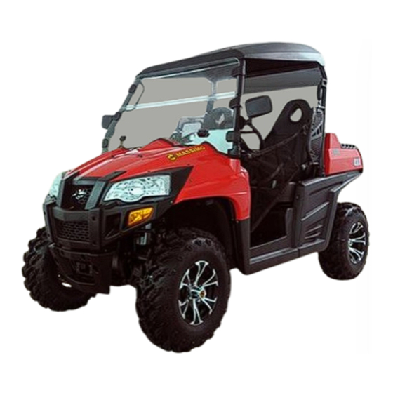
- Page 1 MASSIMO MSU 800 Owner’s Manual...
- Page 2 INTRODUCTION Congratulations on your purchase of the MASSIMO MSU 800 UTV. It represents the result of many years of experience in the production of fine sporting, UTVs, and pacesetting racing machines. With the purchase of this UTV, you can now appreciate the high degree of craftsmanship and reliability.
- Page 3 IMPORTANT MANUAL INFORMATION FAILURE TO FOLLOW THE WARNINGS CONTAINED IN THIS MANUAL CAN RESULT IN SERIOUS INJURY OR DEATH. Particularly important information is distinguished in this manual by the following notations: The Safety Alert Symbol means ATTENTION! YOUR SAFETY IS INVOLVED! Failure to follow WARNING instructions could result in severe injury or death to the machine operator, a bystander or a person inspecting or repairing the machine.
- Page 4 IMPORTANT NOTICE Curve speed must be smaller than 30km/h. This UTV has been passed and the EC certificate, it can run on any public street, road, and highway. Please check your local riding laws and regulations before operating this UTV. When the temperature is below -20℃...
-
Page 5: Table Of Contents
CONTENTS And Differential Gear Lock Switches…4-11 LOCATION OF THE WARNING Accelerator Pedal………………………4-15 AND SPECIFICATION LABELS……1-1 Brake Pedal……………………………4-16 Drive Select Lever……………………4-16 2. SAFETY INFORMATION………………2-1 Fuel Tank Cap…………………………4-17 Seats……………………………………4-17 3. DESCRIPTION AND VEHICLE Seat Moving Forward And IDENTIFICATION………………………3-1 Backward.…………………………………4-19 Identification Number Records…………3-3 Seat Belt………………………………4-19 Vehicle Identification Number…………3-3 Cargo Bed………………………………4-21... - Page 6 Engine/Reduction Gear box Oil ………5-6 Reverse Driving…………………………6-4 Parking……………………………………6-6 Coolant……………………………………5-7 Parking On A Slope……………………6-7 Final Gear Oil……………………………5-8 Vehicle Break-in Period…………………6-8 Differential Gear Oil……………………5-8 Engine Break -In…………………6-9 Adjustment of steering…………………5-8 Accessories And Loading……………6-10 Throttle Pedal……………………………5-9 DRIVING YOUR VEHICLE……………7-1 Throttle Freepaly………………………5-10 Getting To Know Your Vehicle…………7-1 Throttle Freeplay Inspection………5-10 Learning To Operate Your Vehicle……7-5 Throttle Freeplay Ajustment…………5-10...
- Page 7 Trail………………………………………7-18 Rear Brake Pad Check………………8-28 8. PERIODIC MAINTENANCE AND Checking The Brake Fluid Level……8-28 ADJUSTMENT…………………………8-1 Brake Fluid Replacement……………8-30 Owner’s Manual And Tool Kit…………8-1 Checking The Brake Pedal……………8-30 Periodic Maintenance Chart For Checking The Brake Pedal……………8-30 The Emission Control System…………8-3 Parking brake lever free General Maintenance And play adjustment………………………8-31 Lubrication Chart…………………………8-4...
- Page 8 Light Bulb………………………………8-47 Replacing a Rear Turning Light Bulb………………………………8-48 Troubleshooting………………………8-50 Check and solution to Common Problems in Vehicle……………………8-51 CLEANING AND STORAGE…………9-1 A. Cleaning……………………………9-1 B. Storage………………………………9-3 SPECIFICATIONS……………………10-1 FAULT CODE OF ELECLRONIC INJECTION SYSTEM…………………11-1...
-
Page 9: Location Of The Warning And Specification Labels
LOCATION OF THE WARNING AND SPECIFICATION LABELS... - Page 10 Read and understand all of the labels on your vehicle. They contain important information for safe and proper operation of your vehicle. Never remove any labels from your vehicle. If a label becomes difficult to read or comes off, a replacement label is available from your dealer.
-
Page 14: Safety Information
SAFETY INFORMATION This utility vehicle handles differently from other vehicles including cars and UTVs. can result if you do not follow these instructions: SEVERE INJURY OR DEATH Read this manual and all labels carefully and follow the operating procedures described. ●... - Page 15 Always follow the inspection and maintenance procedures and schedules described in this manual. Always keep both hands, arms, feet, and legs inside the vehicle at all times during operation. ● Keep your feet on the floorboard. Never hold onto the enclosure. Otherwise, your hand could be injured if it is caught between the enclosure and an obstacle outside the vehicle.
- Page 16 Always follow proper procedures for going uphill. If you lose control and cannot continue up a hill, ● back down the hill with the engine in reverse gear. Use engine braking to help you go slowly. If necessary, use the brakes gradually to help you go slowly. Always check terrain before going down hills.
- Page 17 WARNING POTENTIAL HAZARD Improper handling of gasoline. WHAT CAN HAPPEN Gasoline can catch fire and you could be burned. HOW TO AVOID THE HAZARD Always turn off the engine when refueling. Do not refuel right after the engine has been running and is still very hot.
- Page 18 WARNING POTENTIAL HAZARD Starting or running the engine in a closed area. WHAT CAN HAPPEN Exhaust fumes are poisonous and may cause loss of consciousness and death within a short time. HOW TO AVOID THE HAZARD Always operate your vehicle in an area with adequate ventilation.
-
Page 19: Description And Vehicle Identification
DESCRIPTION AND VEHICLE IDENTIFICATION Headlights License light Front shock absorber assembly Rear shock absorber assembly Brake fluid reservoir Spark arrester Rear mirror CVT-belt case Driver seat Passenger seat belt Battery Right shoulder protection plate Fuses Spark plug Left shoulder protection plate Oil filter cartridge Driver seat belt Fuel tank cap... - Page 20 Steering wheel On-Command four-wheel-drive and differential lock switches Multi-function display gauge Auxiliary DC jack Passenger handrail Drive select lever Accelerator pedal Brake pedal WARNING Cab nets. Front turning light To protect drivers and passengers’ arm, leg NOTE: and feet, make sure the cab nets is in The vehicle you have purchased may differ slightly from those in the figures of this manual.
-
Page 21: Identification Number Records
Identification Number Records Vehicle Identification Number Record the Vehicle Identification Number and The Vehicle Identification Number is stamped model label information in spaces provided for into the frame. assistance when ordering spare parts from a dealer or for reference in case the vehicle is stolen. -
Page 22: Control Unctions
CONTROL FUNCTIONS Functions of the respective switch positions Ignition Switch are as follows: All electrical circuits are supplied with power, and the headlights and taillights come on when the light switch is on. OFF: All electrical circuits are switched off. The key can be removed in this position. -
Page 23: Switch Lock Assy
CAUTION: Switch Lock Assy Do not operate the electric starter ● continuously for more than 5 seconds, or starter damage could occur. Wait at least 5 seconds between each operation of the electric starter to let it cool. Do not turn the key to the “START” ●... -
Page 24: Indicator And Warning Lights
Indicator and Warning Lights Low-Range Indicator Light “L” This indicator light comes on when the drive select lever is in the “L” position. Parking Brake Indicator Light “P” This indicator light comes on when the parking brake is applied. High-Range Indicator Light “H” High-range indicator light “H”... - Page 25 Neutral Indicator Light “N” “ UNLOCK” position(see pages 4-12). At this moment, rear differential on the rear gear This indicator light comes on when the drive case is locked and the rear differential can select lever is in the “N” position. not work.
- Page 26 wheel-drive switch is set to the “4WD” CAUTION: position. The engine may overheat if the vehicle is overloaded. If this happens, reduce the NOTE: load to specification. Due to the synchronizing mechanism in ● the differential gear case, the four-wheel- After restarting, make sure that the light drive indicator may not come on until the is out.
-
Page 27: Multi-Function Display Gauge
The multi-function meter unit is equipped Multi-Function Display Gauge with the following: Speedometer (which shows the riding speed) Odometer (which shows the total distance traveled) Two trip meters (which show the distance traveled since they were last set to zero) Clock Hour meter (which shows the total time 1. -
Page 28: Odometer And Trip Meter Modes
Odometer and Trip Meter Modes Pushing the “TRIP/ODO” button switches the display between the odometer mode “ODO” and the trip meter modes “A” and “B” in the following order: ODO→TRIP A→ TRIP B → ODO To reset a trip meter, select it by pushing the “TRIP/ODO”... -
Page 29: Clock Mode
Clock Mode Fault Codes Display Of Electronic Injection System Pushing the button switches the display between the clock mode “CLOCK” When the faults come out , meter will display and the hour meter mode “HOUR” in the the fault codes to guide the repair. following order: See attachment for faults code(page 11-1)... -
Page 30: Fuel Gauge
Fuel Gauge The fuel gauge will indicate the fuel volume. As the fuel is running out, the indicator will turn green into red, Vice versa. 1. Rear license bracket 2. Rear license light 1. Fuel level warning indicator 2. Fuel meter... -
Page 31: Switches
Switches CAUTION: Do not use the headlights with the engine turned off for an extended period of time. The battery may discharge to the point that the starter motor will not operate properly. If this should happen, remove the battery and recharge it. -
Page 32: On-Command Four-Wheel-Drive
Select the appropriate drive according to On-Command Four-Wheel–Drive terrain and the conditions. Differential Gear Lock Switches Only rear wheels have differential lock mechanism. Two-wheel drive (”2WD/DIFF-LOCK”): Power is sup- plied to the rear wheels only With the rear wheels differential gear locked (red light “DIFF. - Page 33 the rear wheels only. With the differential WARNING gear of rear wheels unlocked (red light POTENTIAL HAZARD Changing from 2WD to 4WD or from “DIFF.LOCK” is off,) the two rear wheels 2WD to 2WD-Differential UNLOCK, or can turn at different speed. vice-versa while the vehicle is moving.
- Page 34 To change from 4WD to 2WD On-Command Four-Wheel-Drive Switch stop the vehicle, and then set the switch to “2WD/4WD” “2WD”。the 4WD indicator “ ” will go out in the multi-function display. On-Command Differential Gear Lock Switch “2WD/UNLOCK” 1. Select lever 2.
- Page 35 To unlock the differential gear in 2WD WARNING Stop vehicle, make sure POTENTIAL HAZARD On-Command four-wheel-drive switch is set Riding too fast while the vehicle is in to “2WD”, move the select lever to position , 4WD-LOCK. and then set the switch to “UNLOCK”. the WHAT CAN HAPPEN differential gear is unlocked, the differential All wheels turn at the same speed when...
-
Page 36: Accelerator Pedal
fully returns to the idle position as soon as it Accelerator Pedal is released. Press the accelerator pedal down to increase engine speed. Spring pressure returns the WARNING pedal to the rest position when released. POTENTIAL HAZARD Always check that the accelerator pedal Malfunction of the accelerator pedal. -
Page 37: Brake Pedal
Brake Pedal Drive Select Lever Press the brake pedal to slow or stop the The drive select lever is used to shift the vehicle into low, high, neutral and reverse vehicle. positions. (Refer to pages 6-4—6-5 for the drive select lever operation.) 1. -
Page 38: Fuel Tank Cap
Seats Fuel Tank Cap To remove a seat, Remove bolts M6 with Remove the fuel tank cap by turning it socket wrench, and then remove the seat. counter clockwise. Installation is the reverse of removal. 1. Fuel tank cap 1. Driver seat 2. - Page 39 WARNING POTENTIAL HAZARD A loose seat. WHAT CAN HAPPEN The operator could lose control or the operator or passenger could fall if the seat is loose during operation. HOW TO AVOID THE HAZARD Make sure the seat is mounted firmly. 1.Bolt (4×M6) CAUTION: To install the seat, Adjust the four bolts M6...
-
Page 40: Seat Moving Forward And Backward
Moving Seat Forward And Backward. Seat Belt The seat can be moved forward and This vehicle is equipped with three-point seat backward to fit the height of different drivers. belts for both the operator and passenger. Pull up the handle, then you can move the Always wear the seat belt while riding in the seat forward and backward. - Page 41 3. Put the lap portion of the belt low on your To wear the seat belt properly, do the hips. Push down on the buckle end of the following: belt as you pull up on the shoulder part 1. Hold the latch plate as you pull the belt so the belt is snug across your hips.
-
Page 42: Cargo Bed
Cargo Bed WARNING POTENTIAL HAZARD Not wearing the seat belt. Wearing the seat belt improperly. WHAT CAN HAPPEN There is increased risk of being killed or seriously injured in an accident. HOW TO AVOID THE HAZARD Always wear your seat belt when riding 1. - Page 43 WARNING WARNING POTENTIAL HAZARD POTENTIAL HAZARD Overloading the cargo bed. Carrying a passenger in the cargo bed. WHAT CAN HAPPEN WHAT CAN HAPPEN Could cause changes vehicle The passenger could fall, be thrown handling which could lead to an out, or be struck by objects in the cargo accident.
-
Page 44: Front And Rear Shock Absorber Adjustment
Front and Rear Shock Adjustment The spring preload can be adjusted to suit the operating conditions. You can reduce preload for a softer ride, or increase preload if frequent bottoming occurs. CAUTION: Frequent or severe bottoming can cause 1. Spring preload adjusting ring increased wear or damage to the vehicle. -
Page 45: Absorber Adjustment
WARNING POTENTIAL HAZARD Improper shock absorber adjustment. WHAT CAN HAPPEN Uneven adjustment can cause poor handling and loss of stability, which could lead to an accident. HOW TO AVOID THE HAZARD 1. Special wrench Always adjust the shock absorbers on the left and right side to the same setting. -
Page 46: Trailer Hitch Bracket
Auxiliary DC Jack Trailer Hitch Bracket The auxiliary DC jack is located at the right This vehicle is equipped with a 5 cm (2 in) side of the front panel. receiver bracket for a standard trailer hitch. The auxiliary DC jack can be used for Trailer towing equipment can be obtained at suitable work lights, radios, etc. - Page 47 jack. CAUTION: 4. When the auxiliary DC jack is not being Do not use accessories requiring more used, cover it with the cap. than the above maximum capacity. This may overload the circuit and cause the fuse to blow. If accessories are used without the engine running or with the headlights turned on, the battery will lose its charge and engine starting may become difficult.
-
Page 48: Pre-Operation Checks
PRE-OPERATION CHECKS Before using this vehicle, check the following points: ITEM ROUTINE PAGE Check operation, free play, fluid level and fluid leakage. ● Brakes 5-2—5-3,8-26—8-30 Fill with DOT 4 brake fluid if necessary. ● Check for proper operation, condition and free play. ●... -
Page 49: Brakes
Brakes WARNING Always check brake pedal travel and the brake POTENTIAL HAZARD fluid reservoir level before each use of the Failure to inspect the vehicle before vehicle. When applied, the brake pedal should operating. Failure to properly maintain feel firm. Any sponginess would indicate a the vehicle. - Page 50 Check the operation of the brake pedal. Brake Operation should move smoothly and there should be a Test the brakes at slow speed after starting out firm feeling when the brakes are applied. If not, to make sure they are working properly. If the have the vehicle inspected by a dealer.
- Page 51 WARNING POTENTIAL HAZARD Driving with improperly operating brakes. WHAT CAN HAPPEN You could lose braking ability, which could lead to an accident. HOW TO AVOID THE HAZARD Always check the brakes at the start of 1. Parking handbar every ride. Do not operate the vehicle if you find any problem with the brakes.
-
Page 52: Fuel
Your engine has been designed to use regular Fuel Make sure there is sufficient gasoline in the unleaded gasoline with a pump octane number tank. ([R+M] /2) of 86 or higher, or research octane number of 93 or higher. If knocking or pinging Recommended fuel: occurs, use a different brand of gasoline or Unleaded gasoline only... -
Page 53: Engine/Reduction Gear Box Oil
Engine/Reduction Gear box Oil WARNING Make sure the engine/reduction gear box oil is POTENTIAL HAZARD at the specified level. Add oil as necessary. Improper care when refueling. (See pages 8-7 —8-10.) WHAT CAN HAPPEN Fuel can spill, which can cause a fire and CAUTION: severe injury. -
Page 54: Coolant
Coolant WARNING Check the coolant level in the coolant reservoir POTENTIAL HAZARD when the engine is cold. (The coolant level will Removing the radiator cap when the vary with engine temperature.) The coolant engine and radiator are still hot. level is satisfactory if it is between the minimum WHAT CAN HAPPEN and maximum level marks on the coolant reservoir. -
Page 55: Final Gear Oil
Adjustment of steering wheel: : : : Final Gear Oil Make sure the final gear oil is at the specified You can adjust the height of the steering board level. Add oil as necessary. (See pages 8-14 according to the driver’s height and driving —8-15 for details.) habits。... -
Page 56: Throttle Pedal
WARNING Failure to check or maintain proper operation of the throttle system can result in an accident and lead to serious injury or death if the throttle pedal sticks during operation. Never start or operate this vehicle if it has a sticking or improperly operating throttle 1.Adjustable steering column nut 2. -
Page 57: Throttle Freepaly
Throttle Freeplay Throttle Freeplay Ajustment If the throttle pedal has excessive play due to 1. Remove both seats. Remove the middle cable stretch or mis-adjustment, it will cause a cover of the engine, ( see PAGE 8-6 ) delay in throttle response, especially at low 2. -
Page 58: Steering Wheel Inspection
firmly. Wash off any dirt or mud which could Steering Wheel Inspection Check the steering wheel for specified freeplay affect operation. Have a dealer repair as necessary for proper operation. and smooth operation。 1. Position the vehicle on level ground. Fittings and Fasteners 2. -
Page 59: Tires
Tires WARNING POTENTIAL HAZARD Operating this vehicle with improper tires, or with improper or uneven tire pressure. WHAT CAN HAPPEN Use of improper tires on this vehicle, or operation of this vehicle with improper or uneven tire pressure, may cause loss of control, increasing your risk of accident. HOW TO AVOID THE HAZARD 1. - Page 60 under severe riding conditions. The following are minimums: Front 126kpa (0.64kgf/cm , 18psi) Rear 126kpa (0.64kgf/cm , 18psi) 4. Use no more than the following Pressures when seating the tire beads. Front 250kpa (2.5kgf/cm , 36psi) Rear 250kpa (2.5kgf/cm , 36psi) Higher pressures may cause the tire to burst.
-
Page 61: How To Measure Tire Pressure
How to measure tire pressure Use the tire pressure gauge. NOTE: The tire pressure gauge is included as standard equipment. Make two measurements of the tire pressure and use the second reading. Dust or dirt in the gauge could cause the first reading to be incorrect. -
Page 62: Tire Wear Limit
Tire Wear Limit When the tire groove decreases to 3 mm (0.12 in) due to wear, replace the tire. a. Tire wear limit 5-15... -
Page 63: 6. Operation
Starting The Engine In Low OPERATION Temperatures WARNING WARNING POTENTIAL HAZARD POTENTIAL HAZARD Operating vehicle without being Freezing control cables cold familiar with all controls. weather. WHAT CAN HAPPEN WHAT CAN HAPPEN Loss of control, which could cause an You could be unable to control the accident or injury. -
Page 64: Starting The Engine
indicator light does not come on, ask a Starting The Engine dealer to inspect the electric circuit. The engine can be started in any gear if ● CAUTION: See the “Engine Break-In”section prior to the brake is applied. However, it is recommended to shift into neutral ”N”... -
Page 65: Warming Up
Warming Up WARNING To get maximum engine life, always warm up POTENTIAL HAZARD the engine before driving. Never accelerate Engine idle speed exceeds the regula- hard with a cold engine! To see whether or ted speed. not the engine is warm, check if it responds WHAT CAN HAPPEN to the throttle normally . -
Page 66: Drive Select Lever Operation And
Drive Select Lever Operation And Driving In Reverse Before shifting, you must stop the UTV and return the throttle lever to the closed position, otherwise transmission damaged. 1. Drive select lever Shifting: Neutral to High and High to Low 1. Bring the UTV to a complete stop and return the throttle lever to the closed position. - Page 67 1. Bring the UTV to a complete stop and NOTE: return the throttle lever to the closed position. When in reverse, the reverse indicator 2. Apply the brake pedal. light should be on. If the light does not 3. Shift from neutral to reverse and vice come on, ask a dealer to inspect the versa by moving the drive select lever along electrical circuit.
-
Page 68: Parking
Parking WARNING 1. When parking, stop the engine and shift POTENTIAL HAZARD the drive select lever into the neutral Improperly operating in reverse. position. 2. Push the brake pedal down, and pull the WHAT CAN HAPPEN parking brake to top position to park the You could hit an obstacle or person vehicle behind you, resulting in serious injury. -
Page 69: Parking On A Slope
Parking on a slope WARNING POTENTIAL HAZARD Parking on a hill or other incline. WHAT CAN HAPPEN The vehicle could roll out of control, increasing the chance of an accident. 1. Bring the vehicle to a stop by applying HOW TO AVOID THE HAZARD the brakes. -
Page 70: Vehicle Break-In Period
Vehicle Break-in Period The break-in period for your new UTV vehicle is the first 25 hours of operation, or the time it takes to use the first three tanks full of gasoline. No single action on your part is as important as a proper break-in period. Careful treatment of a new engine and drive components will result in more efficient performance and longer life for these... -
Page 71: Engine Break-In
three hours of use. However, momentary (2-3 seconds Use of any engine oil not mentioned in maximum) full throttle operation under load ● this manual will cause severe damage to does not harm the engine. the engine。 Each full throttle acceleration sequence should be followed with a substantial rest period for the engine by cruising at lower Engine Break-In... -
Page 72: Accessories And Loading
Rev the vehicle freely but do not use full light loads. Avoid aggressive acceleration throttle at any time. and high speed operation during the break-in period. After Break-In: Accessories and Loading The vehicle can now be operated normally. Accessories Brake System Break-in Accessories can affect the handing and Apply only moderate braking force for the control of your vehicle. - Page 73 is equivalent in design and quality. Loading Accessories should rigidly Carrying cargo or towing a trailer can change ● securely mounted. An accessory which the stability and handling of a vehicle. can shift position or come off while you You must use common sense and good are operating could affect your ability to judgment when carrying cargo or towing a control the vehicle.
- Page 74 maximum vehicle load limit. Tongue weight (vertical weight on ● trailer hitch point):50kg(110lbs) Load cargo in the cargo bed as close to ● the center of the vehicle as possible and NOTE: tie it down using the cargo hooks Cargo bed : equipped on the cargo bed.
- Page 75 Allow more braking distance. A heavier WARNING ● vehicle takes longer to stop. POTENTIAL HAZARD Avoid making sharp turns unless at very ● Overloading this vehicle or carrying or slow speeds. towing cargo improperly. Avoid hills and rough terrain. Choose ●...
-
Page 76: Driving Your Vehicle
DRIVING YOUR VEHICLE WARNING GETTING TO KNOW YOUR VEHICLE POTENTIAL HAZARD This utility vehicle will handle and maneuver Not wearing the seat belt. differently form an ordinary passenger car or Wearing the seat belt improperly. other vehicle. WHAT CAN HAPPEN Before you begin to use your vehicle, be sure There is increased risk of being killed have... - Page 77 The total weight of operator, passenger, WARNING accessories, cargo, trailer tongue weight, POTENTIAL HAZARD and the vehicle itself must not exceed 829Kg Carrying a passenger in the cargo bed. (1825lb). (See “Loading” on page 6-11.) WHAT CAN HAPPEN Carrying a passenger and cargo can affect The passenger could fall or be struck vehicle handling.
- Page 78 The driver and passenger must always wear WARNING a seat belt and an approved motorcycle POTENTIAL HAZARD Overloading this vehicle or carrying or helmet. Also wear eye protection and towing cargo improperly. protective clothing, including over-the-ankle WHAT CAN HAPPEN boots, gloves, a long-sleeved shirt or jacket, Could cause changes...
- Page 79 HOW TO AVOID THE HAZARD WARNING POTENTIAL HAZARD Always wear an approved motorcycle Operating this vehicle without wearing helmet that fits properly. You should an approved motorcycle helmet, eye also wear: protection, and protective clothing. Eye Protection WHAT CAN HAPPEN (Goggles or Face Shield) Operating without Gloves...
-
Page 80: Learning To Operate Your Vehicle
LEARNING TO OPERATE YOUR VEHICLE Perform the Pre-Operation Checks on pages should become familiar with 5-1-5-15. Set the parking brake, shift to performance characteristics of the vehicle in neutral, and follow the instructions on page a large, flat area that is free of obstacles and 6-1 to start the engine. -
Page 81: Turning Your Vehicle
Position your hands on the steering wheel so 1CAUTION: that your thumbs and fingers do not wrap Do not shift from low to high or vice versa around the wheel. This is particularly without coming to a complete stop and important when driving in rough terrain. -
Page 82: Operating Improperly In Reverse
Operating Improperly in Reverse Improperly operating in reverse could result in a collision with an obstacle or person. Always follow proper operating procedures 。 Follow these precautions when operating in reverse: 1. Always check for obstacles or people behind the vehicle. 2. -
Page 83: Braking
available from your authorized dealer allow BRAKING component identification. Always use the cab Braking ability is affected by the type of terrain. In most cases, gradually application nets and shoulder protection plates. of the brakes is more effective than abrupt braking, particularly on loose surfaces like gravel. - Page 84 WARNING Maximum slope angle: 15° with full POTENTIAL HAZARD loading (300kg) Operating on excessively steep hills. WHAT CAN HAPPEN The vehicle can over turn more easily on extremely steep hills than on level surfaces or small hills. HOW TO AVOID THE HAZARD Never operate your vehicle on hills too steep for it or your abilities.
-
Page 85: Going Downhill
Before climbing the hill, first be sure you are drive select lever in reverse so you can use operating in low range 4WD or, if necessary, the engine brake if necessary to slow your with 4WD Diff. Lock. To climb a hill, you descent. - Page 86 Before starting down hill, make sure the WARNING vehicle is in low-range 4WD. On most POTENTIAL HAZARD slopes, this will let you use engine braking to Going down a hill improperly. help you go downhill slowly. Go as slowly WHAT CAN HAPPEN as possible.
-
Page 87: Crossing Through Shallow Water
WARNING CROSSING THROUGH SHALLOW WATER POTENTIAL HAZARD If you must cross shallow, slow moving water Operating this vehicle through deep or up to the depth of the vehicle’s floorboards, fast-flowing water. choose your path carefully to avoid sharp WHAT CAN HAPPEN drop-offs, large rocks, or slippery surfaces Loss of control, which could result in that could cause the vehicle to overturn. -
Page 88: Vehicle Immersion
1CAUTION: : : : Vehicle Immersion CAUTION: : : : After riding your vehicle in water, be sure to If your vehicle becomes immersed, major drain the trapped water by removing the engine damage can result if the machine is check hose at the bottom of the air filter case, not thoroughly inspected. - Page 89 install new plugs. 6. Attempt to start the engine. If necessary, repeat the drying procedure. 7. Take the vehicle to your dealer for service as soon as possible, whether you succeed in starting it or not. 8. If water has been ingested into the CVT, make sure inspect the hole without water left inside.
-
Page 90: Rear Axle Differential Lock
lock the differential, the rear wheels may continue to slip and will not drive the vehicle ahead. WARNING POTENTIAL HAZARD The rear axle differential is in a locking state while driving on the standard road. 1.CVT Gear Box inspection hole WHAT CAN HAPPEN The vehicle will be difficult to drive, Rear Axle Differential Lock... -
Page 91: Riding Over Rough Terrain
CAUTION: : : : WARNING POTENTIAL HAZARD The differential case in front axle gearbox Failure extra care when uses friction structure and doesn't have lock operating this vehicle on unfamiliar mechanism, so driver don’t need to lock up terrain. WHAT CAN HAPPEN the differential case. -
Page 92: Riding In Brush Or Wooded Areas
Riding In Brush Or Wooded Areas When operating in areas with brush or trees, watch carefully on both sides and above the vehicle for obstacles such as branches that the vehicle might hit, causing an accident, or for brush that might enter the vehicle as you pass and strike the driver or passenger. -
Page 93: Encountering Obstacles On The
Encountering Obstacles On The Trail WARNING If you cannot go around an obstacle such as POTENTIAL HAZARD a fallen tree trunk or a ditch, stop the vehicle Improperly operating over obstacles. where it is safe to do so. Set the parking WHAT CAN HAPPEN brake and get out to inspect the area Could cause loss of control or a... -
Page 94: Periodic Maintenance And Adjustment
PERIODIC MAINTENANCE AND NOTE: ADJUSTMENT If you do not have a torque wrench available during a service operation requiring one, take Periodic inspection, adjustment and lubricat- your vehicle to dealer to check the torque ion will keep your vehicle in the safest and settings and adjust them as necessary. - Page 95 WARNING WARNING POTENTIAL HAZARD POTENTIAL HAZARD Servicing an engine while it is running. Operating this vehicle with improper WHAT CAN HAPPEN modifications. Moving parts can catch clothing or par- WHAT CAN HAPPEN ts of the body, causing injury. Improper installation of accessories or Electrical components can cause sho- modification of this vehicle may cause cks or can start fires.
-
Page 96: Periodic Maintenance Chart For The Emission Control System
Periodic Maintenance Chart for the Emission Control System NOTE: ● For vehicles not equipped with an odometer or hour meter, follow the month maintenance intervals. ● For vehicles equipped with an odometer or an hour meter, follow the km(mi) or hours maintenance intervals. However, keep in mind that if the vehicle isn’t used for a long period of time, the month maintenance intervals should be followed. -
Page 97: General Maintenance And Lubrication Chart
General Maintenance and Lubrication Chart INITIAL EVERY Month Whichever ITEM ROUTINE 1,200 2,400 2,400 4,800 Comes first (mi) (200) (750) (1,500) (1,500) (3,000) hours ● Check coolant leakage. Cooling System ● Repair if necessary. ○ ○ ○ ○ ○ ● Replace coolant every 24 months. Air Filter Elements ●... - Page 98 INITIAL EVERY Month Whichever ITEM ROUTINE 1,200 2,400 2,400 4,800 Comes first (mi) (200) (750) (1,500) (1,500) (3,000) hours ● Check operation and for looseness. Replace if Steering System* damaged. ○ ○ ○ ○ ○ ● Check toe-in. Adjust if necessary Rear Upper and Lower ●...
-
Page 99: Sundry Box Cover
Sundry Box Cover Engine Cover To Open/ Close To Open/ Close Unhook the hood latches, and then slowly tilt 1. Remove two seats ( see page 4-16 ) the sundry box cover up. To close, tilt cover 2. Unscrew all the screws on the engine back to closed position and fasten the cover. -
Page 100: Engine Oil And Oil Filter Cartridge
Engine Oil and Oil Filter Cartridge NOTE: The engine oil level should be checked The engine oil should be between the before each operation. In addition, the oil minimum and maximum level marks. must be changed and the oil filter cartridge replaced at the intervals specified in the periodic maintenance and lubrication chart. -
Page 101: To Change The Engine Oil
To Change the Engine Oil (With or With- NOTE: out Oil Filter Cartridge Replacement) Skip steps 4-6 if the oil filter cartridge is not 1. Remove the console. (See page 8-9 for being replaced. console removal installation 4. Remove the oil filter cartridge with an oil procedures.) filter wrench. - Page 102 Tightening torque: 5. Apply a light coat of engine oil to the Oil filter cartridge: O-ring of the new oil filter cartridge. 17Nm (1.7m·kgf, 12 ft·lbs) NOTE: Make sure the O-ring is seated properly. 1. Oil filler cartridge 2. Torque bolt 7.
- Page 103 8. Add the specified amount of recomme- 1CAUTION: nded engine oil, and then install the In order to prevent clutch slippage (since engine oil filler cap and tighten it. the engine oil also lubricates the clutch), do not mix any chemical additives. Do not use oils with a diesel specification of Recommended engine oil: “CD”...
-
Page 104: To Change The Reduction Gear Box Oil8-11
To change the Reduction Gear Box Oil 1. Remove oil inlet bolt 2. Remove oil outlet bolt, drain the oil of gear box and screw up oil outlet bolt. Final Gear Oil 3. Add sufficient engine oil 4. Screw up oil inlet bolt. 1. - Page 105 Final Gear Oil 3. If the oil is below the brim of the filler hole, Checking the Final Gear Oil Level add sufficient oil of the recommended 1. Place the vehicle on a level surface. type to raise it to the correct level. 2.
- Page 106 Tightening torque: Changing the Final Gear Oil Final gear oil drain bolt: 1. Place the vehicle on a level surface. 20 Nm (2.0 m·kgf, 14 ft·lbs ) 2. Place a container under the final gear case to collect the used oil. 3.
-
Page 107: Differential Gear Oil
6. Install the oil filler bolt, and then tighten it to the specified torque. Tightening torque: Final gear oil filler bolt: 23 Nm (2.3 m·kgf, 16.3 ft·lbs) 7. Check for oil leakage. If oil leakage is found, check for the cause. 1. - Page 108 2. Install the differential gear oil filler bolt, and then tighten it to the specified torque. Tightening torque: Differential gear oil filler bolt: 23Nm (2.3 m·kgf, 16.3 ft·lbs) Changing the Differential Gear Oil 1. Differential gear oil drain bolt 1. Place the vehicle on a level surface. 2.
-
Page 109: Coolant
5. Fill the differential gear case with the Coolant recommended oil. The coolant level should be checked before each ride. Recommended oil: SAE 80 API GL-5 Hypoid gear oil Checking the Coolant Level Oil quantity: 1. Place the vehicle on a level surface. 0.1 L (0.085 lmp qt, 0.105 US qt) 2. - Page 110 1CAUTION: Mix anti freeze with distilled water only. However, if distilled water is not available, soft water may be used for refilling. Changing the Coolant The coolant must be changed by a dealer at the intervals specified in the periodic maintenance and lubrication chart.
-
Page 111: Axle Boots
NOTE: Adding water instead of coolant lowers ● the antifreeze content of the coolant. If water is used instead of coolant, have a dealer check the antifreeze content of the coolant as soon as possible. The radiator fan is automatically switched ●... -
Page 112: Spark Plug Inspection
Spark Plug Inspection Removal Remove hood (See pages 8-6) 2. Remove the spark plug cap. 3. Use the spark plug wrench in the tool kit to remove the spark plug as shown. 1. Spark plug wrench Inspection The spark plug is an important engine component and is easy to inspect. - Page 113 Installation yourself. Instead, take the vehicle to a dealer. You 1. Measure the electrode gap with a wire should periodically remove and inspect the thickness gauge and, if necessary, adjust spark plug because heat and deposits will the gap to specification. cause the spark plug to slowly break down and erode.
- Page 114 Cleaning the Engine Air Filter Element 2. Clean the surface of the spark plug gasket and its mating surface, and then NOTE: wipe off any grime from the spark plug There is a check hose at the bottom of the air threads.
- Page 115 1. Remove the seats. (See pages 4-16 ─ 4. Remove the air filter element. 4-17 for seat removal and installation 5. Remove the sponge material from its procedure.) frame. 2. Remove the Engine cover. (See page 8-9 for Engine cover removal and installation procedure.) 3.
- Page 116 WARNING POTENTIAL HAZARD Using low flash point solvents or gasoline to clean the sponge material. WHAT CAN HAPPEN Low flash point solvents or gasoline can catch fire or explode. HOW TO AVOID THE HAZARD Use parts cleaning solvent to clean the 1.
- Page 117 9. Thoroughly apply foam air filter oil or other quality liquid foam air filter oil (not spray type) to the sponge material. NOTE: The sponge material should be wet but not dripping. 10. Pull the sponge material over its frame. 1.
-
Page 118: Cleaning The Spark Arrester
case for obstructions. Check the air filter Cleaning the Spark Arrester element rubber joint to the carburetor and Be sure the exhaust pipe and muffler are manifold fittings securely to avoid the cool before cleaning the spark arrester. possibility of unfiltered air entering the 1. - Page 119 WARNING POTENTIAL HAZARD Improper cleaning of the spark arrester. Hot exhaust system. WHAT CAN HAPPEN Could injure the eyes. Could cause burns. Could cause carbon monoxide poisoning, possibly leading to death. Could start a fire. HOW TO AVOID THE HAZARD 1.
-
Page 120: Valve Clearance
Front Brake Pad Check Valve Clearance Each brake pad is provided with wear The correct valve clearance changes with indicator grooves, which allow you to check use, resulting in improper fuel-air supply or the brake pad wear without having to engine noise. -
Page 121: Rear Brake Pad Check
NOTE: The wheels need to be removed to check the brake pads. (See pages 8-4-18-42 for wheel removal and installation procedures.) Rear brake pad check Each brake pad is provided with wear indicator grooves, which allow you to check the brake pad wear without having to 1. - Page 122 and the brake system for leakage. level. The brake fluid reservoir is located under the Use only the recommended quality brake fluid. Otherwise, the rubber seals may hood. (See pages 8-7—8-8 for hood opening deteriorate, causing leakage and poor and closing procedure.) braking performance Recommended brake fluid: DOT 4 Refill with the same type of brake fluid.
-
Page 123: Brake Fluid Replacement
Brake Fluid Replacement Complete fluid replacement should be done only by trained service personnel. Have a dealer replace the following components during periodic maintenance or when they are damaged or leaking. Replace the oil seals every two years. Replace the brake hoses every four years. -
Page 124: Parking Brake Lever Free Play Adjustment
Parking brake lever free play adjustment WARNING Periodically check the parking brake lever POTENTIAL HAZARD free play and adjust it if necessary. Operating with improperly serviced or 1. Shift the drive select lever into low gear adjusted brakes. “L”. WHAT CAN HAPPEN 2. - Page 125 1.Locknut 2. Adjusting ntu NOTE: The parking brake lever must be released 6. Turn the adjusting nut in direction when checking and adjusting the parking increase the free play or in direction brake lever free play. to decrease the free play. 7.
-
Page 126: Brake Light Switch Adjustment
Brake Light Switch Adjustment The brake light switch, which is activated by the brake pedal, is properly adjusted when the brake light comes on just before braking takes effect. If necessary, adjust the brake light switch as follows. 10. Open the hood. (See pages 8-7—8-8 for hood opening and closing procedure.) 11. -
Page 127: Cable Inspection And Lubrication
Cable Inspection and Lubrication Lubricate the inner cables and the cable ends. If the cables do not operate smoothly, WARNING ask a dealer to replace them. POTENTIAL HAZARD Damaged control cables. Recommended lubricant: WHAT CAN HAPPEN Engine oil:see page 10-2 Corrosion can result when the outer covering of control cables becomes damaged. -
Page 128: Brake Pedal And Accelerator Pedal Lubrication
Brake Pedal and Accelerator Pedal Lubrication Lubricate the pivoting parts. Recommended lubricant: Lithium-based grease (all-purpose grease) Recommended lubricant: Lithium-based grease Steering Shaft Lubrication Lubricate the pivot points. Recommended lubricant: Rear Knuckle Upper and Lower Pivot Lithium-based grease Lubrication (all-purpose grease) Lubricate the knuckle upper and lower pivots with a grease gun. - Page 129 front balance rod upper universal joint ,steering transmit- ssion shaft rear balance rod lower universal joint ,steering transmit- ssion shaft 8-36...
-
Page 130: Wheel Removal
Wheel Installation Wheel Removal 1. Install the wheel and the nuts. Loosen the wheel nuts. NOTE: Elevate the vehicle and place a suitable The arrow mark on the tire must point ● stand under the frame. toward the rotating direction of the wheel. Remove the nuts from the wheel. -
Page 131: Battery
Battery This vehicle is equipped with a sealed-type battery. Therefore it is not necessary to check the electrolyte or add distilled water in the battery. If the battery seems to have discharged, consult a dealer. 1CAUTION: Do not try to remove the sealing caps of the battery cells. - Page 132 WARNING POTENTIAL HAZARD Failure to handle batteries or battery electrolyte carefully. WHAT CAN HAPPEN You could be poisoned. You could be severely burned by the sulfuric acid in battery electrolyte. Batteries produce explosive gases. HOW TO AVOID THE HAZARD Avoid contact with skin, eyes or clothing. Always shield eyes when working near batteries.
-
Page 133: Battery Maintenance
Battery Maintenance 1CAUTION: special battery charger (constant 1. When the vehicle is not used for a month voltage/ampere or constant voltage) is or longer, remove the battery and store it required for recharging a sealed-type battery. in a cool, dark place. Completely Using a conventional battery charger may recharge the battery before reinstallation. - Page 134 WARNING OTENTIAL HAZARD Using an improper fuse WHAT CAN HAPPEN An improper fuse can cause damage to the electrical system, which could lead to a fire. HOW TO AVOID THE HAZARD Always use a fuse of the specified rating. Never use a material in place 1.
- Page 135 Specified Fuse: Main Fuse: 30.0A Headlight Fuse: 15.0A Ignition Fuse: 10.0A Auxiliary DC Jack Fuse: 10.0A Signaling System Fuse: 10.0A Carburetor Warmer Fuse: 10.0A Four-Wheel-Drive Motor Fuse: 3.0A Backup Fuse: 10.0A 1. Main fuse 2. Spare main fuse 4. Turn the key to “ON” and turn on the 3.
-
Page 136: Replacing A Headlight Bulb
Replacing a Headlight Bulb If a headlight bulb burns out, replace it as follows. 1. Lift the hood up. (See pages 8-7-8-8 for hood opening and closing procedures.) 2. Remove the cover at the rear of the headlight by pulling it off. 1. - Page 137 WARNING POTENTIAL HAZARD A headlight bulb is hot when it is on and immediately after it is turned off. WHAT CAN HAPPEN You can be burned, or a fire could start bulb touches something flammable. HOW TO AVOID THE HAZARD Wait for the bulb to cool before 1.
-
Page 138: Tail/Brake Light Bulb Replacement
7. Install the bulb holder by pushing it in and turning it clockwise. 8. Install the bulb holder cover and the cover at the rear of the headlight. 1CAUTION: Make sure the headlight bulb holder cover is securely fitted over the bulb holder and seated properly. - Page 139 Tail/brake light bulb holder 1. Cargo bed 6. Install the panel by installing the quick 2. Remove the bulb holder (together with fasteners and bolts, and then tighten the the bulb) by turning it counter clockwise. bolts to the specified torque. 3.
-
Page 140: Replacing A Front Turning
Replacing a Front Turning Light Bulb If a front turning light bulb burns out, replace it as follows. 1. Lift the hood up. (See pages 8-7-8-8 for hood opening and closing procedures.) 2. Remove the cover at the rear of the front turning light by pulling it off. -
Page 141: Replacing A Rear Turning Light Bulb
Replacing a Rear Turning Light Bulb If a rear turning light bulb burns out, replace it as follows. 1. Lift the hood up. (See pages 8-7-8-8 for hood opening and closing procedures.) 2. Remove the cover at the rear of the rear turning light by pulling it off. - Page 142 1. Rear turning light bulb holder cover 1. Rear turning light bulb holder 4. Remove the rear turning light bulb holder by pushing it in and turning it counter clockwise. 5. Remove the defective bulb by pulling it out. 6. Insert a new rear turning light bulb into the bulb holder by pushing it in.
-
Page 143: Troubleshooting
Troubleshooting WARNING Although vehicles receive a rigid inspection POTENTIAL HAZARD before shipment from the factory, trouble Checking fuel system while may occur during operation. Any problem smoking or near an open flame. WHAT CAN HAPPEN in the fuel, compression, or ignition systems Fuel can ignite or explode, causing can cause poor starting and loss of power. -
Page 144: Check And Solution To Common Problems In Vehicle
Check and solution to Common Problems in Vehicle Here you can see some tables on the common problems which may come up when you are driving a UTV, which will help to solve these problems. To repair a UTV requires technical skills, if you cannot fix it up yourself , please contact your dealer. - Page 145 : : : : Table 2 Check and Solution of Common Problems in Brake System . Problems Solutions 1.Check if the handle of parking brake return to its position. Brake system is locked 2.Check if the brake discs are deformed. 3.Check if the calipers' hydraulic cylinders get stuck, or the fixing parts of calipers are deformed.
- Page 146 Problems Solutions 1.Check if left & right brake force' deviation of front brake is with specified limit. 2.Check if the brake force of front brake go down, which Vehicle deflected cause the rear wheels are locked up before the front wheels when braked.
- Page 147 Problems Solutions 2.Check if the differential lock control magneto plug in rear rear differential won't bridge reduction gear box are broken. work. 3.Check if the wire is broken. 1.Check if the sensor is broken. Meter display abnormal- 2.Check if the meter is broken. 3.Check if the surface of speed sensor is contamniated with iron dust.
- Page 148 Problems Solutions 2.Check the main ball pins to find out if they are broken. 3.Check the lock screws of front wheels and axles to find out if they are loose or broken. Front wheels shake seri- 4.Check the inner splines of front wheel hubs and outer ously in running.
- Page 149 Problems Solutions 1.Check if overloaded. 2.Check if the springs are two soft after after long time Shock absorbers beco- running. me soft and not comfort- table in running. 3.Check if the shock absorbers lose their damping force in their travel. 1.Check if the spline of intermediate driving shaft is broken.
- Page 150 Table5: Check and Solution of Common Problems in Engine System Problems Solutions 1. Check the throttle cable for seizure 2. Check the adjustment knob of carburetor for damage or Idle speed can not be wear adjusted 3.Check the needle of carburetor to see if it can be placed to the bottom 1.Check the battery voltage for Within specified value 2.Check the rectifier output voltage for within specified...
- Page 151 Problems Solutions 1.Check the cooling fin of radiator for blocked by soil or dirt 2.Check the speed sensor of radiator for damage and Check fan for failure Coolant boils 3.Check if antifreeze can meet the requirement stated in the owner manual. 4.Check the coolant loop for mixed with air 1.Check the battery ,which with low electricity may cause the motor failure...
- Page 152 WARNING POTENTIAL HAZARD Removing the radiator cap when the engine and radiator are still hot. WHAT CAN HAPPEN You could be burned by hot fluid and steam blown out under pressure. HOW TO AVOID THE HAZARD Wait for the engine to cool before removing the radiator cap. Always use a thick rag over the cap.
- Page 153 PERIODIC MAINTENANCE AND NOTE: ADJUSTMENT If you do not have a torque wrench available during a service operation requiring one, take Periodic inspection, adjustment and lubricat- your vehicle to dealer to check the torque ion will keep your vehicle in the safest and settings and adjust them as necessary.
- Page 154 WARNING WARNING POTENTIAL HAZARD POTENTIAL HAZARD Servicing an engine while it is running. Operating this vehicle with improper WHAT CAN HAPPEN modifications. Moving parts can catch clothing or par- WHAT CAN HAPPEN ts of the body, causing injury. Improper installation of accessories or Electrical components can cause sho- modification of this vehicle may cause cks or can start fires.
- Page 155 Periodic Maintenance Chart for the Emission Control System NOTE: ● For vehicles not equipped with an odometer or hour meter, follow the month maintenance intervals. ● For vehicles equipped with an odometer or an hour meter, follow the km(mi) or hours maintenance intervals. However, keep in mind that if the vehicle isn’t used for a long period of time, the month maintenance intervals should be followed.
- Page 156 General Maintenance and Lubrication Chart INITIAL EVERY Month Whichever ITEM ROUTINE 1,200 2,400 2,400 4,800 Comes first (mi) (200) (750) (1,500) (1,500) (3,000) hours ● Check coolant leakage. Cooling System ● Repair if necessary. ○ ○ ○ ○ ○ ● Replace coolant every 24 months. Air Filter Elements ●...
- Page 157 INITIAL EVERY Month Whichever ITEM ROUTINE 1,200 2,400 2,400 4,800 Comes first (mi) (200) (750) (1,500) (1,500) (3,000) hours ● Check operation and for looseness. Replace if Steering System* damaged. ○ ○ ○ ○ ○ ● Check toe-in. Adjust if necessary Rear Upper and Lower ●...
- Page 158 Sundry Box Cover Engine Cover To Open/ Close To Open/ Close Unhook the hood latches, and then slowly tilt 1. Remove two seats ( see page 4-16 ) the sundry box cover up. To close, tilt cover 2. Unscrew all the screws on the engine back to closed position and fasten the cover.
- Page 159 Engine Oil and Oil Filter Cartridge NOTE: The engine oil level should be checked The engine oil should be between the before each operation. In addition, the oil minimum and maximum level marks. must be changed and the oil filter cartridge replaced at the intervals specified in the periodic maintenance and lubrication chart.
- Page 160 To Change the Engine Oil (With or With- NOTE: out Oil Filter Cartridge Replacement) Skip steps 4-6 if the oil filter cartridge is not 1. Remove the console. (See page 8-9 for being replaced. console removal installation 4. Remove the oil filter cartridge with an oil procedures.) filter wrench.
- Page 161 Tightening torque: 5. Apply a light coat of engine oil to the Oil filter cartridge: O-ring of the new oil filter cartridge. 17Nm (1.7m·kgf, 12 ft·lbs) NOTE: Make sure the O-ring is seated properly. 1. Oil filler cartridge 2. Torque bolt 7.
- Page 162 8. Add the specified amount of recomme- 1CAUTION: nded engine oil, and then install the In order to prevent clutch slippage (since engine oil filler cap and tighten it. the engine oil also lubricates the clutch), do not mix any chemical additives. Do not use oils with a diesel specification of Recommended engine oil: “CD”...
- Page 163 To change the Reduction Gear Box Oil 1. Remove oil inlet bolt 2. Remove oil outlet bolt, drain the oil of gear box and screw up oil outlet bolt. Final Gear Oil 3. Add sufficient engine oil 4. Screw up oil inlet bolt. 1.
- Page 164 Final Gear Oil 3. If the oil is below the brim of the filler hole, Checking the Final Gear Oil Level add sufficient oil of the recommended 1. Place the vehicle on a level surface. type to raise it to the correct level. 2.
- Page 165 Tightening torque: Changing the Final Gear Oil Final gear oil drain bolt: 1. Place the vehicle on a level surface. 20 Nm (2.0 m·kgf, 14 ft·lbs ) 2. Place a container under the final gear case to collect the used oil. 3.
- Page 166 6. Install the oil filler bolt, and then tighten it to the specified torque. Tightening torque: Final gear oil filler bolt: 23 Nm (2.3 m·kgf, 16.3 ft·lbs) 7. Check for oil leakage. If oil leakage is found, check for the cause. 1.
- Page 167 2. Install the differential gear oil filler bolt, and then tighten it to the specified torque. Tightening torque: Differential gear oil filler bolt: 23Nm (2.3 m·kgf, 16.3 ft·lbs) Changing the Differential Gear Oil 1. Differential gear oil drain bolt 1. Place the vehicle on a level surface. 2.
- Page 168 5. Fill the differential gear case with the Coolant recommended oil. The coolant level should be checked before each ride. Recommended oil: SAE 80 API GL-5 Hypoid gear oil Checking the Coolant Level Oil quantity: 1. Place the vehicle on a level surface. 0.1 L (0.085 lmp qt, 0.105 US qt) 2.
- Page 169 1CAUTION: Mix anti freeze with distilled water only. However, if distilled water is not available, soft water may be used for refilling. Changing the Coolant The coolant must be changed by a dealer at the intervals specified in the periodic maintenance and lubrication chart.
- Page 170 NOTE: Adding water instead of coolant lowers ● the antifreeze content of the coolant. If water is used instead of coolant, have a dealer check the antifreeze content of the coolant as soon as possible. The radiator fan is automatically switched ●...
- Page 171 Spark Plug Inspection Removal Remove hood (See pages 8-6) 2. Remove the spark plug cap. 3. Use the spark plug wrench in the tool kit to remove the spark plug as shown. 1. Spark plug wrench Inspection The spark plug is an important engine component and is easy to inspect.
- Page 172 Installation yourself. Instead, take the vehicle to a dealer. You 1. Measure the electrode gap with a wire should periodically remove and inspect the thickness gauge and, if necessary, adjust spark plug because heat and deposits will the gap to specification. cause the spark plug to slowly break down and erode.
-
Page 173: Cleaning
Cleaning the Engine Air Filter Element 2. Clean the surface of the spark plug gasket and its mating surface, and then NOTE: wipe off any grime from the spark plug There is a check hose at the bottom of the air threads. - Page 174 1. Remove the seats. (See pages 4-16 ─ 4. Remove the air filter element. 4-17 for seat removal and installation 5. Remove the sponge material from its procedure.) frame. 2. Remove the Engine cover. (See page 8-9 for Engine cover removal and installation procedure.) 3.
- Page 175 WARNING POTENTIAL HAZARD Using low flash point solvents or gasoline to clean the sponge material. WHAT CAN HAPPEN Low flash point solvents or gasoline can catch fire or explode. HOW TO AVOID THE HAZARD Use parts cleaning solvent to clean the 1.
- Page 176 9. Thoroughly apply foam air filter oil or other quality liquid foam air filter oil (not spray type) to the sponge material. NOTE: The sponge material should be wet but not dripping. 10. Pull the sponge material over its frame. 1.
- Page 177 case for obstructions. Check the air filter Cleaning the Spark Arrester element rubber joint to the carburetor and Be sure the exhaust pipe and muffler are manifold fittings securely to avoid the cool before cleaning the spark arrester. possibility of unfiltered air entering the 1.
- Page 178 WARNING POTENTIAL HAZARD Improper cleaning of the spark arrester. Hot exhaust system. WHAT CAN HAPPEN Could injure the eyes. Could cause burns. Could cause carbon monoxide poisoning, possibly leading to death. Could start a fire. HOW TO AVOID THE HAZARD 1.
- Page 179 Front Brake Pad Check Valve Clearance Each brake pad is provided with wear The correct valve clearance changes with indicator grooves, which allow you to check use, resulting in improper fuel-air supply or the brake pad wear without having to engine noise.
- Page 180 NOTE: The wheels need to be removed to check the brake pads. (See pages 8-4-18-42 for wheel removal and installation procedures.) Rear brake pad check Each brake pad is provided with wear indicator grooves, which allow you to check the brake pad wear without having to 1.
- Page 181 and the brake system for leakage. level. The brake fluid reservoir is located under the Use only the recommended quality brake fluid. Otherwise, the rubber seals may hood. (See pages 8-7—8-8 for hood opening deteriorate, causing leakage and poor and closing procedure.) braking performance Recommended brake fluid: DOT 4 Refill with the same type of brake fluid.
- Page 182 Brake Fluid Replacement Complete fluid replacement should be done only by trained service personnel. Have a dealer replace the following components during periodic maintenance or when they are damaged or leaking. Replace the oil seals every two years. Replace the brake hoses every four years.
- Page 183 Parking brake lever free play adjustment WARNING Periodically check the parking brake lever POTENTIAL HAZARD free play and adjust it if necessary. Operating with improperly serviced or 1. Shift the drive select lever into low gear adjusted brakes. “L”. WHAT CAN HAPPEN 2.
- Page 184 1.Locknut 2. Adjusting ntu NOTE: The parking brake lever must be released 6. Turn the adjusting nut in direction when checking and adjusting the parking increase the free play or in direction brake lever free play. to decrease the free play. 7.
- Page 185 Brake Light Switch Adjustment The brake light switch, which is activated by the brake pedal, is properly adjusted when the brake light comes on just before braking takes effect. If necessary, adjust the brake light switch as follows. 10. Open the hood. (See pages 8-7—8-8 for hood opening and closing procedure.) 11.
- Page 186 Cable Inspection and Lubrication Lubricate the inner cables and the cable ends. If the cables do not operate smoothly, WARNING ask a dealer to replace them. POTENTIAL HAZARD Damaged control cables. Recommended lubricant: WHAT CAN HAPPEN Engine oil:see page 10-2 Corrosion can result when the outer covering of control cables becomes damaged.
- Page 187 Brake Pedal and Accelerator Pedal Lubrication Lubricate the pivoting parts. Recommended lubricant: Lithium-based grease (all-purpose grease) Recommended lubricant: Lithium-based grease Steering Shaft Lubrication Lubricate the pivot points. Recommended lubricant: Rear Knuckle Upper and Lower Pivot Lithium-based grease Lubrication (all-purpose grease) Lubricate the knuckle upper and lower pivots with a grease gun.
- Page 188 front balance rod upper universal joint ,steering transmit- ssion shaft rear balance rod lower universal joint ,steering transmit- ssion shaft 8-36...
- Page 189 Wheel Installation Wheel Removal 1. Install the wheel and the nuts. Loosen the wheel nuts. NOTE: Elevate the vehicle and place a suitable The arrow mark on the tire must point ● stand under the frame. toward the rotating direction of the wheel. Remove the nuts from the wheel.
- Page 190 Battery This vehicle is equipped with a sealed-type battery. Therefore it is not necessary to check the electrolyte or add distilled water in the battery. If the battery seems to have discharged, consult a dealer. 1CAUTION: Do not try to remove the sealing caps of the battery cells.
- Page 191 WARNING POTENTIAL HAZARD Failure to handle batteries or battery electrolyte carefully. WHAT CAN HAPPEN You could be poisoned. You could be severely burned by the sulfuric acid in battery electrolyte. Batteries produce explosive gases. HOW TO AVOID THE HAZARD Avoid contact with skin, eyes or clothing. Always shield eyes when working near batteries.
- Page 192 Battery Maintenance 1CAUTION: special battery charger (constant 1. When the vehicle is not used for a month voltage/ampere or constant voltage) is or longer, remove the battery and store it required for recharging a sealed-type battery. in a cool, dark place. Completely Using a conventional battery charger may recharge the battery before reinstallation.
- Page 193 WARNING OTENTIAL HAZARD Using an improper fuse WHAT CAN HAPPEN An improper fuse can cause damage to the electrical system, which could lead to a fire. HOW TO AVOID THE HAZARD Always use a fuse of the specified rating. Never use a material in place 1.
- Page 194 Specified Fuse: Main Fuse: 30.0A Headlight Fuse: 15.0A Ignition Fuse: 10.0A Auxiliary DC Jack Fuse: 10.0A Signaling System Fuse: 10.0A Carburetor Warmer Fuse: 10.0A Four-Wheel-Drive Motor Fuse: 3.0A Backup Fuse: 10.0A 1. Main fuse 2. Spare main fuse 4. Turn the key to “ON” and turn on the 3.
- Page 195 Replacing a Headlight Bulb If a headlight bulb burns out, replace it as follows. 1. Lift the hood up. (See pages 8-7-8-8 for hood opening and closing procedures.) 2. Remove the cover at the rear of the headlight by pulling it off. 1.
- Page 196 WARNING POTENTIAL HAZARD A headlight bulb is hot when it is on and immediately after it is turned off. WHAT CAN HAPPEN You can be burned, or a fire could start bulb touches something flammable. HOW TO AVOID THE HAZARD Wait for the bulb to cool before 1.
- Page 197 7. Install the bulb holder by pushing it in and turning it clockwise. 8. Install the bulb holder cover and the cover at the rear of the headlight. 1CAUTION: Make sure the headlight bulb holder cover is securely fitted over the bulb holder and seated properly.
- Page 198 Tail/brake light bulb holder 1. Cargo bed 6. Install the panel by installing the quick 2. Remove the bulb holder (together with fasteners and bolts, and then tighten the the bulb) by turning it counter clockwise. bolts to the specified torque. 3.
- Page 199 Replacing a Front Turning Light Bulb If a front turning light bulb burns out, replace it as follows. 1. Lift the hood up. (See pages 8-7-8-8 for hood opening and closing procedures.) 2. Remove the cover at the rear of the front turning light by pulling it off.
- Page 200 Replacing a Rear Turning Light Bulb If a rear turning light bulb burns out, replace it as follows. 1. Lift the hood up. (See pages 8-7-8-8 for hood opening and closing procedures.) 2. Remove the cover at the rear of the rear turning light by pulling it off.
- Page 201 1. Rear turning light bulb holder cover 1. Rear turning light bulb holder 4. Remove the rear turning light bulb holder by pushing it in and turning it counter clockwise. 5. Remove the defective bulb by pulling it out. 6. Insert a new rear turning light bulb into the bulb holder by pushing it in.
- Page 202 Troubleshooting WARNING Although vehicles receive a rigid inspection POTENTIAL HAZARD before shipment from the factory, trouble Checking fuel system while may occur during operation. Any problem smoking or near an open flame. WHAT CAN HAPPEN in the fuel, compression, or ignition systems Fuel can ignite or explode, causing can cause poor starting and loss of power.
- Page 203 Check and solution to Common Problems in Vehicle Here you can see some tables on the common problems which may come up when you are driving a UTV, which will help to solve these problems. To repair a UTV requires technical skills, if you cannot fix it up yourself , please contact your dealer.
- Page 204 : : : : Table 2 Check and Solution of Common Problems in Brake System . Problems Solutions 1.Check if the handle of parking brake return to its position. Brake system is locked 2.Check if the brake discs are deformed. 3.Check if the calipers' hydraulic cylinders get stuck, or the fixing parts of calipers are deformed.
- Page 205 Problems Solutions 1.Check if left & right brake force' deviation of front brake is with specified limit. 2.Check if the brake force of front brake go down, which Vehicle deflected cause the rear wheels are locked up before the front wheels when braked.
- Page 206 Problems Solutions 2.Check if the differential lock control magneto plug in rear rear differential won't bridge reduction gear box are broken. work. 3.Check if the wire is broken. 1.Check if the sensor is broken. Meter display abnormal- 2.Check if the meter is broken. 3.Check if the surface of speed sensor is contamniated with iron dust.
- Page 207 Problems Solutions 2.Check the main ball pins to find out if they are broken. 3.Check the lock screws of front wheels and axles to find out if they are loose or broken. Front wheels shake seri- 4.Check the inner splines of front wheel hubs and outer ously in running.
- Page 208 Problems Solutions 1.Check if overloaded. 2.Check if the springs are two soft after after long time Shock absorbers beco- running. me soft and not comfort- table in running. 3.Check if the shock absorbers lose their damping force in their travel. 1.Check if the spline of intermediate driving shaft is broken.
- Page 209 Table5: Check and Solution of Common Problems in Engine System Problems Solutions 1. Check the throttle cable for seizure 2. Check the adjustment knob of carburetor for damage or Idle speed can not be wear adjusted 3.Check the needle of carburetor to see if it can be placed to the bottom 1.Check the battery voltage for Within specified value 2.Check the rectifier output voltage for within specified...
- Page 210 Problems Solutions 1.Check the cooling fin of radiator for blocked by soil or dirt 2.Check the speed sensor of radiator for damage and Check fan for failure Coolant boils 3.Check if antifreeze can meet the requirement stated in the owner manual. 4.Check the coolant loop for mixed with air 1.Check the battery ,which with low electricity may cause the motor failure...
- Page 211 WARNING POTENTIAL HAZARD Removing the radiator cap when the engine and radiator are still hot. WHAT CAN HAPPEN You could be burned by hot fluid and steam blown out under pressure. HOW TO AVOID THE HAZARD Wait for the engine to cool before removing the radiator cap. Always use a thick rag over the cap.
-
Page 212: Specifications
SPECIFICATIONS Model 800UTV-EC Dimensions: Overall length 2,700mm (106.3 in) Overall width 1,360mm (53.5in) Overall height 1,840mm (73.2 in) Seat height 800mm (31.5 in) Wheelbase 1,940mm (76.4 in) Ground clearance 260 mm (10.2 in) Minimum turning radius 6,730 mm (265 in) Basic weight: 526.0 kg (1,508 lb) With oil and full fuel tank... - Page 213 Model 800UTV-EC Engine oil: Type API service SG type or higher, JASO standard MA Recommended engine oil classification 1CAUTION: In order to prevent clutch slippage (since the engine oil also lubricates the clutch), do not mix any chemical additives. Do not use oils with a diesel specification of “CD”...
- Page 214 Model 800UTV-EC Final gear case oil: Type SAE80 API GL-4 Hypoid gear oil Quantity: 0.40L (0.35 lmp qt, 0.41 US qt) Differential gear case oil: Type SAE80 API GL-5 Hypoid gear oil Quantity: 0.10L (0.08 lmp qt, 0.1 US qt) Radiator capacity (including all routes): 2.50L (2.20 lmp qt, 2.64 US qt) Air filter:...
- Page 215 Model 800UTV-EC Transmission: Primary reduction system CVT-belt Secondary reduction system Shaft drive CVT reduction ratio 0.68-2.7 Transmission type CVT-belt automatic Operation Right hand operation Reverse gear 5.45 Sub transmission ratio 5.29 High 2.866 Chassis: Frame type Steel tube frame Caster angle 1.0°...
- Page 216 Model 800UTV-EC Brakes: System Front and rear unified Type Front Dual disc brake Rear Dual disc brake Operation Foot operation Suspension: Front suspension Double wishbone Rear suspension Double wishbone Shock absorber: Front shock absorber Coil spring/oil damper Rear shock absorber Coil spring/oil damper Wheel travel: Front wheel travel...
- Page 217 Model 800UTV-EC Bulb voltage, wattage × quantity: Headlight 12V35.0W/35.0W × 2 Tail/brake light 12V5.0W/21.0W × 2 Front/Rear turning light 12V10.0W/10.0W × 2 License light 12V3.0W Indicator lights: Neutral indicator light Reverse indicator light Coolant temperature warning light Parking brake indicator light Diff-lock indicator On-Command differential gear lock indicator light High-range indicator light...
-
Page 218: Fault Code Of Eleclronic Injection System
Fault Code of Eleclronic Injection System DTC Description Related Calibration Number P0107 MAP Circuit Low Voltage or Open KsDGDM_MAP_ShortLow P0108 MAP Circuit High Voltage KsDGDM_MAP_ShortHigh P0112 IAT Circuit Low Voltage KsDGDM_IAT_ShortLow P0113 IAT Circuit High Voltage or Open KsDGDM_IAT_ShortHigh Coolant/Oil Temperature Sensor Circuit P0117 KsDGDM_CoolantShortLow Low Voltage... - Page 219 P0031 O2S Heater Circuit High Voltage KsDGDM_O2_HeaterShortHigh P0032 O2S Heater Circuit Low Voltage KsDGDM_O2_HeaterShortLow P0201 Injector 1 Circuit Malfunction KsDGDM_INJ_CYL_A_Fault P0202 Injector 2 Circuit Malfunction KsDGDM_INJ_CYL_B_Fault P0230 FPR Coil Circuit Low Voltage or Open KsDGDM_FPP_CircuitShortLow P0232 FPR Coil Circuit High Voltage KsDGDM_FPP_CircuitShortHigh P0336 CKP Sensor Noisy Signal...
- Page 220 P1694 Tachometer Circuit High Voltage KsDGDM_TAC_Circuit_High 1694 5780 P0137 O2S 2 Circuit Low Voltage KsDGDM_O2_2_ShortLow P0138 O2S 2 Circuit High Voltage KsDGDM_O2_2_ShortHigh P0038 O2S Heater 2 Circuit High Voltage KsDGDM_O2_HeaterShortHigh P0037 O2S Heater 2 Circuit Low Voltage KsDGDM_O2_HeaterShortLow P0500 VSS No Signal KsDGDM_VSS_NoSignal 1280 P0850...
Need help?
Do you have a question about the MSU 800 and is the answer not in the manual?
Questions and answers
Having hard time figuring out how to check and change oil
To check and change the oil on a Massimo MSU 800, follow these steps:
1. Checking the Oil Level
- Ensure the vehicle is on a level surface.
- Remove the dipstick and wipe it clean.
- Reinsert the dipstick fully, then remove it again to check the oil level.
- The oil level should be between the dipstick’s upper and lower marks.
- Add oil if necessary, but do not overfill.
2. Changing the Oil and Oil Filter
- Warm up the engine to help the oil flow out easily.
- Turn off the engine and allow it to cool slightly.
- Place a drain pan under the oil drain plug.
- Unscrew the oil drain plug and let the oil drain completely.
- Remove the oil filter cover and take out the old oil filter.
- Replace it with a new oil filter and check the cover O-ring, replacing it if necessary.
- Reinstall the oil drain plug securely.
- Add new oil to the engine through the dipstick opening.
- Recheck the oil level after a few minutes and adjust if needed.
- Properly tighten the dipstick.
Always follow proper safety precautions to avoid burns from hot oil.
This answer is automatically generated