
Related Manuals for Massimo 60"


Summary of Contents for Massimo 60"
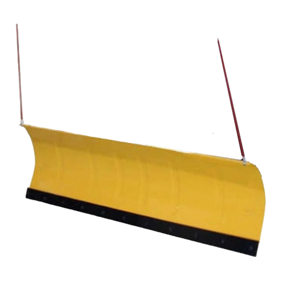
- Page 1 @MASSIMO OPERATOR'S MANUAL 60"/72" Snow Plow for A TV/UTV IMPORTANT READ INSTRUCTIONS CAREFULLY BEFORE OPERATION...
- Page 2 11mportant Safe Operation Practices WARNING: This symbol points out important safety instructions which, if not fol l owed, could endanger the personal safety and/or property of yourself and others. Read and follow all instructions in this manual before attempting to operate this machine.
- Page 4 " • � · - - The Snow : : P o Plow Assembly o - U-sc rew bolt .lJ .li , , /i /7 , -Gasket fi r ii iifl ri IMPORTANT: Refer to your ATV/UTV Owner's Manual Picture 1 for any inform ation relating to the use of your vehcile.
- Page 5 Snow Plow Assembly Picture 3 Picture 2 2: Attaching blade adjustment base component. Fix the Blade adjustment base (20), Blade adjustment dial (19), Base of blade adjuster (18) by Hexagon head flange bolts (17) and Nuts (20) to lift arm (22). Refer to the Picture 3 show. IMPORTANT: Refer to your ATV/UTV Owner's Manual...
- Page 6 4: Attaching the Snow blade to the Lift arm component. Mount the snow blade to the lift arm component by screws (?), washer (6&5), and nuts (4). Refer to the picture 6. Connecting the Lift arm component and blade via Tension spring(3) and Hook bolt (12). Refer to the picture 7&8.
- Page 7 Warning: .,.,,,lllll/y,.-ll1lfllllldt:llllllllll/Jllallldl:lllltlfJI/IJl1111""11t:lltntl 1. For the difference between the different vehicles, the operation method of rising and lowering the snow shovel will be different. Please read the ATV/UTV manual carefully and operate according to the vehicle requirements. 2. The snow plough has two skid shoes. Lowering the skid shoes will raise the snow plough and raising the skid shoes will lower the Operating snow plough.
Need help?
Do you have a question about the 60" and is the answer not in the manual?
Questions and answers