Table of Contents
Advertisement
Quick Links
Advertisement
Table of Contents

Related Manuals for BH FITNESS LK500FT


Summary of Contents for BH FITNESS LK500FT
- Page 1 LK500FT LK500FT REV-0 5/14/14 OWNER’S MANUAL Important: Read all instructions carefully before using this product. Retain this owner’s manual for future reference. BH North America | 20155 Ellipse, Foothill Ranch, California 92610 | p.949.206.0330 | f.949.206.0350 | www.BHFitnessUSA.com...
-
Page 2: Table Of Contents
TABLE OF CONTENTS Title Page Introduction Warnings and Labels Anchoring the Unit Important Safety Instructions Training Guidelines Suggested Stretches Assembly Instructions Pre-assembled Components Parts List Maintenance & Cleaning Warranty... -
Page 3: Introduction
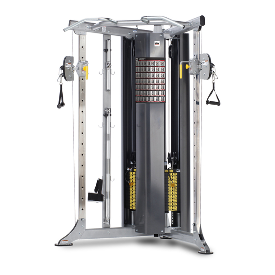
L 51” X W 51” X H 83” CDP-300 WEIGHT: 600 lbs Congratulations on your purchase of BH Fitness equipment. We hope you appreciate the style, quality, and value that exercisers around the world have come to expect from BH Fitness. -
Page 4: Warnings And Labels
WARNINGS AND LABELS BNH2924 BNH3145 LK500FT BH Fitness | 20155 Ellipse, Foothill Ranch, CA 92610 | Toll Free: 866.325.2339 | www.BHFitnessUSA.com Use only genuine BH replacement parts. Failure to do so will void warranty and could result in serious injury or death. - Page 5 BNH2925 BHF2903 BNH2926 BNH2912 BNH2916 BNH2916 BNH3089 BNH3146 BNH2908 BNH2908 BHF3147 BNH3089...
- Page 6 BNH2926 BNH3146 BHF2903 BNH3145 BNH3089 BNH2908 BNH2924 BNH2916 BNH2925 BNH2912 BHF3149 LK500FT BHF3134 BH Fitness | 20155 Ellipse, Foothill Ranch, CA 92610 | Toll Free: 866.325.2339 | www.BHFitnessUSA.com BHF3150...
- Page 7 You should have received it along with this Owners Manual. If you did not receive this Sign with your order, you can obtain one at no cost to you from BH Fitness by contacting our service department at: Toll Free: 866.325.2339 customersupport@bhnorthamerica.com...
-
Page 8: Anchoring The Unit
ANCHORING THE UNIT Holes on footplates are provided for anchoring the unit to the floor. (See anchoring hole locations below) ANCHORING HOLE ANCHORING HOLE ANCHORING HOLES BNH3089... -
Page 9: Important Safety Instructions
IMPORTANT SAFETY INSTRUCTIONS It is the responsibility of the facility owner and/or owner of the equipment to review the Owner’s Manual with their facility personnel and understand all Danger, Warning and Caution labels affixed on the machine. It is the responsibility of the floor personnel to instruct users on proper operation of the equipment and review all danger, warning and caution labels. -
Page 10: Training Guidelines
TRAINING GUIDELINES Exercise is one of the most important factors in the overall health of an individual. Listed among its benefits are: • Increased capacity for physical work (strength endurance) • Increased cardiovascular (heart and arteries/veins) and respiratory efficiency • Decreased risk of coronary heart disease •... - Page 11 OXYGEN UPTAKE The effort that you can exert over a prolonged period of time is limited by your ability to deliver oxygen to the working muscles. Regular vigorous exercise produces a training effect that can increase your aerobic capacity by as much as 20 to 30%. An increased VO2 Max indicates an increased ability of the heart to pump blood, of the lungs to ventilate oxygen, and of the muscles to take up oxygen.
- Page 12 HEART RATE As you exercise, your heart beat increases. This is often used as a measure of the required intensity of an exercise. You need to exercise hard enough to condition your circulatory system, and increase your pulse rate, but not enough to strain your heart. Your initial level of fitness is important when developing an exercise program for you.
- Page 13 MUSCLE SORENESS For the first week or so, muscle soreness may be the only indication you have that you are on an exercise program. This, of course, does depend on your overall fitness level. A confirmation that you are on the correct program is a very slight soreness in most major muscle groups. This is quite normal and will disappear in a matter of days.
-
Page 14: Suggested Stretches
SUGGESTED STRETCHES Head Rolls Rotate your head to the right for one count while feeling the stretch up the left side of your neck. Next, rotate your head back for one count, stretching your chin to the ceiling. Rotate your head to the left for one count, and finally, drop your head to your chest for one count. - Page 15 SUGGESTED STRETCHES Inner Thigh Stretch Sit with the soles of your feet together with your knees pointing outward. Pull your feet as close into your groin as possible. Gently push your knees towards the floor. Hold for 15 counts. Toe Touches Slowly bend forward from your waist, letting your back and shoulders relax as you stretch toward your toes.
-
Page 16: Assembly Instructions
ASSEMBLY INSTRUCTIONS... - Page 17 Step 1 Assembly List Item Qty. Description BLACK NYLON PULLEY WIDE GROOVE 3/8 X 1 X 3 1/2 FLANGED SPACER Z/P 3/8 X 16.5MM HEX HEAD CAP SCREW GR-5 Z/P 3/8-16 X 2 9/16 NYLON INSERT THIN PATTERN LOCK NUT Z/P 3/8-16 BASE FRAME, LEFT SIDE ASSEMBLY BASE FRAME, RIGHT SIDE ASSEMBLY Fully Tighten...
- Page 18 Step 2 Assembly List Item Qty. Description HEX HEAD CAP SCREW GR-5 Z/P 3/8-16 X 1 HEX HEAD CAP SCREW GR-5 Z/P 3/8-16 X 3 SPLIT LOCK WASHER Z/P 3/8" FLAT WASHER SAE Z/P 3/8" NYLON INSERT THIN PATTERN LOCK NUT Z/P 3/8-16 REAR UPRIGHT ASSEMBLY BASE FRAME, LEFT SIDE ASSEMBLY BASE FRAME, RIGHT SIDE ASSEMBLY...
- Page 19 Step 3 Assembly List Item Qty. Description SELECTOR POST CARRIAGE RT CARRIAGE LT Note: It is strongly recommended that two people participate in this assembly step. *13 *14 Note: Position reference numbers facing toward the inside of the unit.
- Page 20 Step 4 Assembly List Item Qty. Description SELECTOR POST NYLON SPACER 3/8 X 7/8 X 3/8 HEX HEAD CAP SCREW GR-5 Z/P 3/8-16 X 2 9/16 HEX HEAD CAP SCREW GR-5 Z/P 3/8-16 X 3 FLAT WASHER SAE Z/P 3/8" NYLON INSERT THIN PATTERN LOCK NUT Z/P 3/8-16 Note: It is strongly recommended that two...
- Page 21 Loosely Tighten Loosely tighten all hardware in this step. DO NOT Fully Tighten. Some component(s) may need pre-assembly and or alignment during the assembly process. Step 5 Assembly List Item Qty. Description BLACK NYLON PULLEY WIDE GROOVE 3/8 X 1 X 3 1/2 HEX HEAD CAP SCREW GR-5 Z/P 3/8-16 X 2 1/2 SPLIT LOCK WASHER Z/P 1/2"...
- Page 22 Step 6 Assembly List Item Qty. Description HEX HEAD CAP SCREW GR-5 Z/P 3/8-16 X 1 3/4 HEX HEAD CAP SCREW GR-5 Z/P 3/8-16 X 4 FLAT WASHER SAE Z/P 3/8" NYLON INSERT THIN PATTERN LOCK NUT Z/P 3/8-16 TOP FRAME, LEFT SIDE ASSEMBLY TOP FRAME, RIGHT SIDE ASSEMBLY Note: • It is strongly recommended that two people...
- Page 23 Loosely Tighten Loosely tighten all hardware in this step. DO NOT Fully Tighten. Some component(s) may need pre-assembly and or alignment during the assembly process. Note: • It is strongly recommended that two people participate in this assembly step. • Some parts have been removed for Clarity. Step 7 Assembly List Item...
- Page 24 Standard 150 lbs Weight Stacks Note: Threaded Sockets toward the top of the unit. Step 8 150 lbs Wt Stacks Assembly List Item Qty. Description GUIDE ROD FLAT WASHER Z/P 3/4 X 2 WEIGHT STACK SPACER 1 1/4 RD X 5 RUBBER DONUT 3/4 X 2 1/2 HEX HEAD CAP SCREW GR-5 Z/P 3/8-16 X 2 3/4 SPLIT LOCK WASHER Z/P 3/8"...
- Page 25 with Upgraded 200 lbs Weight Stacks Note: Threaded Sockets toward the top of the unit. Step 8 200 lbs Wt Stacks Assembly List Item Qty. Description GUIDE ROD RUBBER DONUT 3/4 X 2 1/2 HEX HEAD CAP SCREW GR-5 Z/P 3/8-16 X 2 3/4 SPLIT LOCK WASHER Z/P 3/8"...
- Page 26 NOTE: 1. TOP PLATE LABEL GOES ON HOLE OFF CENTER AS SHOWN BELOW. LABEL WILL COVER HOLE ON CENTER. Weight stack labels and lubrication instructions 1. Wipe front surface of weight stack with rubbing alcohol and wipe dry. 2. Peel off back sheet (adhesive side) from label (#86) and make sure that the label remains attached to the application tape.
- Page 27 Note: Install Plastic Insert Cap #75 after Making sure the Cable is running over the two Reinforcement Tubes. Reinforcement Tubes Note: • Make sure the cable runs in the grooves of the pulleys. Note: • It is strongly recommended that two people Continue on Next Page. participate in this assembly step. • Some parts have been removed for Clarity.
- Page 28 Step 11 Assembly List Item Qty. Description BLACK NYLON PULLEY WIDE GROOVE 3/8 X 1 X 3 1/2 CABLE CDP-300 HEX HEAD CAP SCREW GR-5 Z/P 3/8-16 X 2 1/2 FLAT WASHER SAE Z/P 3/8" NYLON INSERT THIN PATTERN LOCK NUT Z/P 3/8-16 CABLE STOPPER SHELL 1 1/2 X 1 3/4 7/8 RD X 1 5/8 LINK 1/8 CABLE OVAL HEAD SCREW Z/P #10-32 X 1 1/8...
- Page 29 Note: Install Plastic Insert Cap #75 after Making sure the Cable is running over the two Reinforcement Tubes. Reinforcement Tubes Note: • Make sure the cable runs in the grooves of the pulleys. Note: Continue on Next Page. • It is strongly recommended that two people participate in this assembly step. • Some parts have been removed for Clarity.
- Page 30 Step 13 Assembly List Item Qty. Description BLACK NYLON PULLEY WIDE GROOVE 3/8 X 1 X 3 1/2 CABLE CDP-300 HEX HEAD CAP SCREW GR-5 Z/P 3/8-16 X 2 1/2 FLAT WASHER SAE Z/P 3/8" NYLON INSERT THIN PATTERN LOCK NUT Z/P 3/8-16 CABLE STOPPER SHELL 1 1/2 X 1 3/4 7/8 RD X 1 5/8 LINK 1/8 CABLE OVAL HEAD SCREW Z/P #10-32 X 1 1/8...
- Page 31 Step 14 Fully Tighten Note: It is strongly recommended that two 100% people participate in this assembly step. Proceed to inspect; align and wrench tighten ALL hardware assemblies specially those left loosely fasten, making sure the unit is assembled square and perpendicular.
- Page 32 Step 15 Assembly List Note: • It is strongly recommended that two people Item Qty. Description participate in this assembly step. HEX HEAD CAP SCREW GR-5 Z/P 1/4-20 X 3/4 FLAT WASHER USS Z/P 1/4" • Some parts have been removed for Clarity. REAR SHROUD, LEFT SIDE ASSEMBLY REAR SHROUD, RIGHT SIDE ASSEMBLY Fully Tighten 41 28...
- Page 33 Step 16 Assembly List Item Qty. Description Note: HEX HEAD CAP SCREW GR-5 Z/P 1/4-20 X 3/4 • It is strongly recommended that two people FLAT WASHER USS Z/P 1/4" participate in this assembly step. FRONT SHROUD ASSEMBLY • Some parts have been removed for Clarity. Fully Tighten 100% Wrench tighten all hardware in this step.
- Page 34 Fully Tighten 100% Wrench tighten all hardware in this step. Note: • It is strongly recommended that two people participate in this assembly step. • Some parts have been removed for Clarity. Step 17 Assembly List Item Qty. Description HEX HEAD CAP SCREW GR-5 Z/P 3/8-16 X 3 1/2 FLAT WASHER SAE Z/P 3/8"...
- Page 35 Step 18 Assembly List Item Qty. Description NYLON ANKLE STRAP LOW ROW BAR 1 1/4 ALUMINUM SQUAT BAR 46" DOUBLE LINK (TUBULAR) CONTOUR ERGO HANDLE LONG STRAP SNAP LINK Z/P 8MM X 80MM...
-
Page 36: Pre-Assembled Components
PRE-ASSEMBLED COMPONENTS CABLE FISHING STRING TO FACILITATE ROUTING THE CABLE. CABLE FISHING STRING TO FACILITATE ROUTING THE CABLE. - Page 37 Use onl y gen par ts. uin e BH and cou Fail ure to do rep lace ld res so wil me nt ult in ser iou l voi d wa rran s inju ry or dea Re com me nd BH Pa Use only whe n...
- Page 38 63 69 78 62 90 94...
-
Page 41: Parts List
BHF3138 BHF3149 Hex head cap screw gr-5 z/p 3/8-16 x 2 1/2 BNH2044 Excecise chart LK500FT decal Hex head cap screw gr-5 z/p 3/8-16 x 2 3/4 BNH2045 Label caution check pull-pin is fully... 1 1/2 X 1 3/8 BNH2912... - Page 42 Top frame, right side assembly UP8069X1 1 10 Lb top plate w/adj sltr bar 19 blk wts assy BNH1982X3 Adjustable pulley bracket assembly UP8074X1 2 Cable assembly LK500FT UP8078X1 Chin up cross brace assembly UP8070X1 1 Rear shroud, right side assembly UP8075X2...
-
Page 43: Maintenance & Cleaning
MAINTENANCE AND CLEANING Care has been taken to assure that your equipment has been properly adjusted and lubricated at the factory. It is not recommended that the user attempt service on the internal components. Instead, seek service from an authorized service center. However, you may clean the outer surface. -
Page 44: Warranty
LIGHT COMMERCIAL WARRANTY This warranty applies only in the United States to the products manufactured or distributed by BH Fitness under the BH Fitness brand name. BH warrants to the original purchaser that BH equipment will be free from defects in material and workmanship. All warranty periods begin to run from the date of purchase to the original purchaser.
Need help?
Do you have a question about the LK500FT and is the answer not in the manual?
Questions and answers