Table of Contents
Advertisement
Quick Links
Advertisement
Table of Contents

Related Manuals for BH FITNESS Dual Adjustable Pulley


Summary of Contents for BH FITNESS Dual Adjustable Pulley
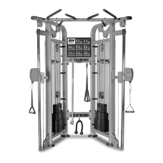
- Page 1 Dual Adjustable Pulley OWNER’S MANUAL Important: Read all instructions carefully before using this product. Retain this owner’s manual for future reference. BH North America | 20155 Ellipse, Foothill Ranch, California 92610 | p.949.206.0330 | f.949.206.0013 | www.BHFitnessUSA.com...
-
Page 2: Table Of Contents
TABLE OF CONTENTS Title Page Introduction Safety Information Exercise Instruction Training Guidelines Suggested Stretches Assembly Instructions Maintenance and Cleaning Exploded View Drawing Parts List Warranty... -
Page 3: Introduction
INTRODUCTION Congratulations on your purchase of BH strength equipment. We hope you appreciate the style, quality, and value that exercisers around the world have come to expect from Strength Fitness. If you have any questions, concerns or product issues please call our Customer Service Team at 1-866-325-2339 or email us at CustomerSupport@BHNorthAmerica.com. -
Page 4: Safety Information
6. This machine must only be used for the purposes described in this manual. DO NOT use accessories that are not recommended by BH Fitness. Read manual prior to use and follow all warnings and instructions. 7. Do not place sharp objects near the machine. -
Page 5: Exercise Instruction
EXERCISE INSTRUCTION Use of the machine offers various benefits; it can improve fitness, muscle tone and when used in conjunction with a calorie controlled diet, it can help you lose weight. 1. Consult your doctor before starting any exercise program. It is advisable to undergo a complete physical examination. -
Page 6: Training Guidelines
TRAINING GUIDELINES Exercise is one of the most important factors in the overall health of an individual. Listed among its benefits are: • Increased capacity for physical work (strength endurance) • Increased cardiovascular (heart and arteries/veins) and respiratory efficiency • Decreased risk of coronary heart disease •... - Page 7 OXYGEN UPTAKE The effort that you can exert over a prolonged period of time is limited by your ability to deliver oxygen to the working muscles. Regular vigorous exercise produces a training effect that can increase your aerobic capacity by as much as 20 to 30%. An increased VO2 Max indicates an increased ability of the heart to pump blood, of the lungs to ventilate oxygen, and of the muscles to take up oxygen.
- Page 8 HEART RATE As you exercise, your heart beat increases. This is often used as a measure of the required intensity of an exercise. You need to exercise hard enough to condition your circulatory system, and increase your pulse rate, but not enough to strain your heart. Your initial level of fitness is important when developing an exercise program for you.
- Page 9 MUSCLE SORENESS For the first week or so, muscle soreness may be the only indication you have that you are on an exercise program. This, of course, does depend on your overall fitness level. A confirmation that you are on the correct program is a very slight soreness in most major muscle groups. This is quite normal and will disappear in a matter of days.
-
Page 10: Suggested Stretches
SUGGESTED STRETCHES Head Rolls Rotate your head to the right for one count while feeling the stretch up the left side of your neck. Next, rotate your head back for one count, stretching your chin to the ceiling. Rotate your head to the left for one count, and finally, drop your head to your chest for one count. - Page 11 SUGGESTED STRETCHES Inner Thigh Stretch Sit with the soles of your feet together with your knees pointing outward. Pull your feet as close into your groin as possible. Gently push your knees towards the floor. Hold for 15 counts. Toe Touches Slowly bend forward from your waist, letting your back and shoulders relax as you stretch toward your toes.
-
Page 12: Assembly Instructions
ASSEMBLY INSTRUCTIONS... - Page 13 STEP 1 Tip: Fasten hardware only hand tight until all Crossbars have been attached, then fully tighten all hardware. Use wrench (not supplied) to tighten the following: Attach the 2 Crossbars (3) to the Right Frame (2) and the Left Frame (1) using attaching hardware (38, 65, 70, 73).
- Page 14 STEP 2 The Swivel Pulley Housing (6) and the Adjuster Lever Assembly (7, 8) are pre-assembled. Attach Swivel Pulley Housing (6) to Left Adjuster Lever Assembly (7) as seen below (dashed lines) using attaching hardware (24, 33, 34, 63, 69, 72). Attach Swivel Pulley Housing (6) to Right Adjuster Lever Assembly (8) in the same manner.
- Page 15 STEP 3 Make sure adjustment holes on Adjuster Tube (5) are facing the center of the machine and not outward. Insert bottom part of the Adjuster Tube (5) on to the Left Frame (1) as shown below and attach the top part of Adjuster Tube (5) using attaching hardware (39, 44, 61, 64, 69, 72).
- Page 16 STEP 4 Tip: Fasten hardware only hand tight until Shield (45) is attached, then fully tighten all hardware. Attach four Connect Plates (17) to the outer side of Left Frame (1) using attaching hardware (56, 67). Attach four Connect Plates (17) to the outer side of Right Frame (2) in the same manner.
- Page 17 STEP 5 Tip: Fasten hardware only hand tight until Shield (45) is attached, then fully tighten all hardware. Attach four Connect Plates (17) to the inner side of Left Frame (1) using attaching hardware (56, 67). Attach four Connect Plates (17) to the inner side of Right Frame (2) in the same manner.
- Page 18 STEP 6 Caution: For safety, the following assembly will require two people. Remove the four screws (36) and only loosen the Socket Set Screws (53) from the two Guide Rods (19). Have one person pull the two Guide Rods (19) away from the Left Frame (1) so as to allow room to install the 15 lb Weight Plates (77).
- Page 19 STEP 7 Refer to Step 8 and Step 9 diagrams for reference on cable installation routing direction. Remove Threaded Tube Nut from Threaded Tube. Take Cable (21) and tape (use any adhesive tape) Threaded Tube on to Cable as shown in Figure 7-3 below. This will prevent the Threaded Tube from sliding on the cable.
- Page 20 STEP 8 Install Big Pulley (40) hand tight using attaching hardware (59, 69, 72) on Left Frame (1), everywhere shown in Step 7 and Step 8 diagrams. Note the installation of the Big Half Round Plate (14), Small Half Round Plate (15) and Round Plate (16) locations shown below. Use the same assembly instuctions as above for the Right Frame (2).
- Page 21 STEP 9 Tighten hardware with wrench.
- Page 22 STEP 10 Install Poster Board (10) above upper Crossbar (3) with attaching hardware (56, 67) as shown in diagram below.
- Page 23 STEP 11 Install Shield (45) to Left Frame (1) with attaching hardware (58, 68) as shown in the diagram below. Use the same assembly instuctions as above for the Right Frame (2).
-
Page 24: Maintenance And Cleaning
MAINTENANCE AND CLEANING Care has been taken to assure that your equipment has been properly adjusted and lubricated at the factory. It is not recommended that the user attempt service on the internal components. Instead, seek service from an authorized service center. However, you may clean the outer surface. -
Page 25: Exploded View Drawing
EXPLODED VIEW DRAWING... - Page 26 EXPLODED VIEW DRAWING...
-
Page 27: Parts List
PARTS LIST To order replacement parts: provide your customer service representative with the product model number and the part number located on the Parts List below, along with the quantity you require. DESCRIPTION Q'TY DESCRIPTION Q'TY Left Frame Number Label Right Frame 40X80mm Ellipse Inner Cap Crossbar... -
Page 28: Warranty
* Applies to defects from the manufacturer only. FOR WARRANTY REPAIRS, PLEASE DO NOT TAKE YOUR MACHINE BACK TO THE RETAIL STORE. CONTACT BH FITNESS FIRST. BH North America Corporation 20155 Ellipse Foothill Ranch, CA 92610 Phone: 949.206.0330;...
Need help?
Do you have a question about the Dual Adjustable Pulley and is the answer not in the manual?
Questions and answers