Table of Contents
Advertisement
Quick Links
Advertisement
Table of Contents

Subscribe to Our Youtube Channel
Related Manuals for Avermedia NV3000T


Summary of Contents for Avermedia NV3000T
- Page 1 NV Card Series 3000/5000/6000E/7240/7480/8416E4 V7.7(SP4) April 2011...
- Page 3 TRADEMARKS "AVerMedia" is a registered trademark of AVerMedia Technologies, Inc and has been authorized AVerMedia Information Inc to use. “AVerDiGi” and “AVer” are trademarks (or registered trademarks) of AVerMedia Information, Inc. All other products or corporate names mentioned in this documentation are for identification and explanation purposes only, and may be trademarks or registered trademarks of their respective owners.
- Page 4 COPYRIGHT © 2011 AVerMedia Information, Inc. All rights reserved. No part of this document may be reproduced, transmitted, transcribed, stored in a retrieval system, transmitted in any form, or translated into any language by any means (electronically, mechanically, photocopied, recorded, etc.) without the prior written permission of AVerMedia.
-
Page 5: Table Of Contents
NV3000T H ..................18 ARDWARE NSTALLATION 2.4.1 Installing NV3000T and I/O Audio cards (optional) ............18 2.4.2 Installing (2) NV3000T and (2) I/O Audio cards (optional) ..........18 2.4.3 Installing (4) NV3000T cards ..................19 NV5000T H ..................19 ARDWARE NSTALLATION 2.5.1... - Page 6 AMERAS UDIO DEVICE 2.11.1 Connecting the Cameras, a TV and Audio device to NV3000T/5000T ......32 2.11.2 Connecting the Cameras, a TV and Audio devices to NV6000T ........33 2.11.3 Connecting the Cameras, a TV and Audio devices to NV7240/NV7480 ......34 2.11.4 Connecting the Cameras, a LCD Monitor, and Audio devices to NV8416T ....
- Page 7 CHAPTER 3 SOFTWARE INSTALLATION ................45 NV DVR S XP/V /7 ....... 46 NSTALLING OFTWARE AND RIVERS IN INDOWS ISTA CHAPTER 4 USING THE NV DVR SOFTWARE ................ 47 NV DVR S ..................47 UNNING THE OFTWARE ................... 47 SING THE IRTUAL EYBOARD ..........
- Page 8 Switching to USB DVR Mode ..................113 Switching to 485 DVR Mode ..................114 Switch Control on Multiple DVR Servers ..............115 Familiarizing with LCD Screen ................... 116 Operating the LCD Menu ................... 117 Select a Camera ......................119 Locking System Operation ..................120 Trigger the Alarm Button ....................
- Page 9 ......................189 ETWORK ETTING ......................192 CHEDULE ETTING 5.5.1 To set schedule at a specific portion of time in that hour: ..........194 ......................195 ACKUP ETTING 5.6.1 Setup Quick Backup ....................196 ......................197 ENSOR ETTING ........................ 198 ELAY ETTING 5.8.1 To Setup External I/O Box ..................
- Page 10 Network Setting ........................240 Schedule Setting ........................243 Alarm Setting .......................... 245 PTZ B ..............250 AMILIARIZING THE IEWER UTTONS ..............251 AMILIARIZING THE EMOTE ONSOLE UTTONS 8.3.1 To Setup Remote Console Setting ................252 PTZ C ..........254 AMILIARIZING THE UTTONS IN AMERA ONTROLLER...
- Page 11 CHAPTER 11 WEB TOOLS ....................... 292 11.1 ......................292 ISPATCH ERVER 11.1.1 To Run Dispatch program ................... 292 11.2 ........................ 293 EMOTE ETUP 11.2.1 To Add DVR server ..................... 293 11.2.2 To Setup Remote DVR Server ..................294 Network Setting ........................304 11.3 ......................
- Page 13 Manual Conventions The following conventions are used throughout this manual. Caution symbol is intended to alert the user of the important installation and operating instructions. Fail to comply may damage the system. Information symbol is intended to provide additional information for the purpose of clarification.
-
Page 15: Chapter 1 Introduction
Chapter 1 Introduction AVerMedia AVerDVR is a 32-bit PCI video capture card that works as a digital video surveillance system. It enables you to capture true color images and real-time videos from 4 up to 16 camera inputs simultaneously. With the latest Motion Detection technology, you no longer need to monitor every single moment of the day;... -
Page 16: Nv5000T Optional Accessories
NV5000T Optional Accessories (1) I/O Audio card (2) I/O Box Please refer to Chapter 2.14 for installation NV6000T Package NV6000T package includes the following: (1) NV6000T (3) 2X AV cable (5) Installation CD (7) I/O cable (6240T/6480T) (2) I/O card (4) Quick Guide (6) 30cm Watchdog line... -
Page 17: Nv7240/7480 Package
NV7240/7480 Package NV7480 package includes the following: (1) NV7240/7480 (5) AV cable (2) I/O card (6) I/O cable (3) Installation CD (7) Watchdog line (4) Quick Installation Guide NV8416T Package NV8416T package includes the following: (1) NV8416T (4) AV cable (2) Installation CD (5) AV cable (3) Quick Installation Guide... -
Page 18: Nv9416T Package
NV9416T Package NV9416T package includes the following: (10) (11) (1) NV9416T (5) Quick Installation Guide (9) Audio transmitting cable(#2/27cm) (2) Daughter card (6) AV cable (10) Watchdog line (3) I/O card (7) AV cable (11) I/O cable (4) Installation CD (8) 3x Video transmitting cable(#1/25cm) OSD kit (optional) -
Page 19: Nv3000T Card Parts
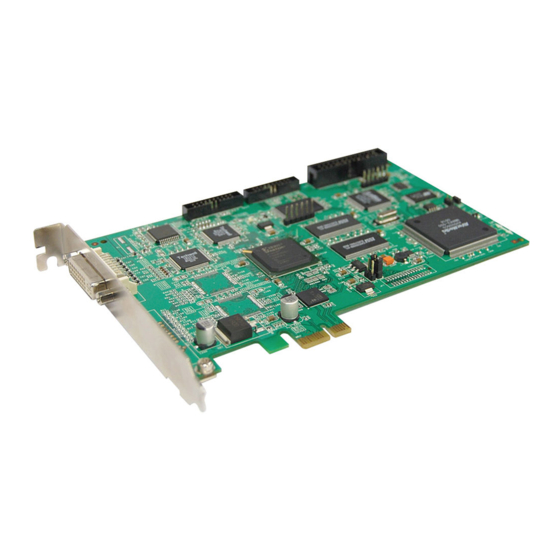
NV3000T Card Parts TV out link connector Audio pin TV out port I/O connector Reset pin video in ports Watchdog pin NV5000T Card Parts Video extension card connectors Display card connector TV out link Audio connector connector TV out port... -
Page 20: Nv7240/7480 Card Parts
NV7240/7480 Card Parts Connector for Display 21 card I/O connector Reset pin Watchdog pin TV Out Port DVI AV In Port NV8416T Card Parts I/O connector Connector for Display 21 card Reset pin Watchdog pin DVI AV In Port DVI AV In Port... -
Page 21: Nv9416T Card Parts
NV9416T Card Parts NV9416T Video Transmitting Audio Transmitting Video Transmitting Connector Connector Power Connector Connector Watch Dog I/O Card Connector Reset Pin Display 21 Card Connector NV9416T Daughter Card Video & Audio Transmitting Connector DVI AV In Port Display 21 Card Connector DVI AV In Port IR USB Receiver Part &... -
Page 22: Chapter 2 Hardware Installation
Chapter 2 Hardware Installation Minimum System Requirements Verify if the computer meets the minimum system requirements. NV3000T/5000T: NV3000T NV5000T Pentium 4 2.8GHz or above recommended Motherboard Intel 865, 875, 915, 925, 945, 955, NVIDIA nFORCE4 SLi - Intel Edition Chipset Windows XP Professional 32bit /Windows Vista 32bit/Windows 7 32/64bit - For Windows Vista, do the following setting in order to operate DVR normally. - Page 23 32-bit high color SVGA graphics card with 128MB video memory and DirectDraw/ YUV Rendering Capability Audio Sound card and speakers Ethernet 10/100/1000 Base-T Ethernet card ® For AVerMedia Security Product Hardware Recommendation list update, → AVerDiGi NV series → select go to http://www.avermedia.com/AVerDiGi/Product/ the NV card → Hardware Recommendations...
- Page 24 32-bit high color SVGA graphics card with 128MB video memory and DirectDraw/ YUV Rendering Capability Audio Sound card and speakers Ethernet 10/100/1000 Base-T Ethernet card ® For AVerMedia Security Product Hardware Recommendation list update, → AVerDiGi NV series → select go to http://www.avermedia.com/AVerDiGi/Product/ the NV card → Hardware Recommendations NV8416T:...
- Page 25 NV9416T: Motherboard Suggested motherboard in our website. → AverDiGi NV series → http://www.avermedia.com/AVerDiGi/Product/ NV9416T → Hardware Recommendations Core2Duo E82 2.66GHz CPU is highly recommended Hard disk 120GB or higher120GB or higher Windows XP Professional 32bit /Windows Vista 32bit/Windows 7 32bit...
-
Page 26: System Requirement And Performance Recommendation
System Requirement and Performance Recommendation Verify if the computer meets the minimum system requirements from the below chart in order to meet the demand of the performance. 2.2.1 Pure NVR User can calculate the total resolution (MegaPixel) of IP cameras that plans to connected and map to the below chart to find out the system requirement and performance. - Page 27 Guaranteed Performance: Total MegaPixel (MP) 25 ~ 28 Microsoft Windows XP / Windows Vista / Windows 7 Codec Type MPEG4 17-32 MP Record (fps) 30 fps per Channel 17-32 MP Preview ( fps ) 7 fps per channel 【CASE 2】 8 IP cameras in 1.3MP and 4 IP cameras in 2MP 4 D1 mode IP cameras Total MegaPixel is 8 * 1.3MP + 4 * 2MP + 4 * 0.25(VGA/D1 = 1/4 MP) = 19.4MP...
-
Page 28: Hybrid Dvr
2.2.2 Hybrid DVR User can calculate the requirement value of IP cameras and NV card from below chart to find out the system requirement and performance. System Requirement: Total MegaPixel 1 ~ 4 5 ~ 8 9 ~ 16 17 ~ 20 21 ~ 24 25 ~ 28 29 ~ 32... - Page 29 System Requirement would be as following: Value 2400 ~ 2799 Intel Core 2 Quad Q6600 2.4GHz nVidia GeForce 8500 GT 256 MB or above Ethernet Gigabit LAN Guaranteed performance would be as following: Value 2400 ~ 2799 Microsoft Windows XP / Windows Vista /Windows 7 Codec Type MPEG4 17-32 MP...
-
Page 30: Nv3000T/5000T/6000T/7240/7480/8416T/9416T Hardware Combinations
NV3000T/5000T/6000T/7240/7480/8416T/9416T Hardware Combinations AVerMedia NV DVR provides powerful surveillance functions and flexible hardware combinations. The table shows the numbers of camera inputs, audio inputs, sensor inputs and relay outputs on different hardware combinations. Before installing the cards, the computer must be turned OFF, the power cable must be UNPLUGGED and all other cables that are attached at the back of the computer must be DISCONNECTED. - Page 31 NV6000T hardware combinations: Hardware Combinations Camera Audio Relay Sensor Input Input Input Output NV6480T Card IO Card Hardware Combinations Camera Audio Relay Sensor Input NV6240T Card IO Card Input Input Output (8Channels) NV7240 hardware combinations: Hardware Combinations Audio Camera Input Sensor Input Relay Output Input...
-
Page 32: Nv3000T Hardware Installation
The I/O audio card is an optional item. The D-type I/O port receives and transmit signal from the I/O box where the sensor and relay device are connected to it, while the audio input port receives the signal from the microphone NV3000T card is compatible with I/O Audio card that supports one audio input only. -
Page 33: Installing (4) Nv3000T Cards
1. Remove the PC case cover. 2. Remove 4 brackets that cover the PCI slots. Save the screws. 3. Connect the (4) NV3000T cards with the supplied 20cm video signal line. 4. Press the cards into the PCI slots firmly. -
Page 34: Installing Nv5000T And I/O Audio Cards
2.5.2 Installing NV5000T and I/O Audio cards The I/O audio card is an optional item. The D-type I/O port receives and transmit signal from the I/O box where the sensor and relay device are connected to it, while the audio input port receives the signal from the microphone NV5000T card is compatible with the I/O Audio card that supports four (4) audio inputs. -
Page 35: Installing Nv5000T, I/O Audio (Optional) And Bnc Video Extension Card (Optional)
2.5.4 Installing NV5000T, I/O Audio (optional) and BNC video extension card (optional) Remove the PC case cover. Remove 3 brackets that cover the PCI slots. Save the screws. Connect the NV5000T card, BNC video extension card and I/O Audio card with the connection cables. -
Page 36: Installing Nv5000T, Video Extension Card (Optional), And I/O Audio (Optional)
2.5.6 Installing NV5000T, Video extension card (optional), and I/O Audio (optional) 1. Remove the PC case cover. 2. Remove 3 brackets that cover the PCI slots. Save the screws. 3. Connect the NV5000T card, video extension card and I/O Audio card with the connection cables. 4. -
Page 37: Nv6000T Hardware Installation
NV6000T Hardware Installation The NV6000T can support up to 16 cameras and 8 audio inputs 2.6.1 Installing (2) NV6000T card The PC motherboard needs to have 2 PCI-Ex1 slots for installing 2 NV6000T card. 1. Remove the PC case cover. 2. -
Page 38: Nv7240/Nv7480 Hardware Installation
NV7240/NV7480 Hardware Installation 2.7.1 Installing NV7240/NV7480 card 1. Remove the PC case cover. 2. Remove 1 bracket that cover the PCI slots and save the screws. 3. Press the NV card into the PCI slot firmly. 4. Secure the card with the screws. 5. -
Page 39: Installing Nv7240/Nv7480, I/O Card, And Display 21 Card (Optional)
2.7.3 Installing NV7240/NV7480, I/O card, and Display 21 card (optional) 1. Remove the PC case cover. 2. Remove 3 brackets that cover the PCI slots. Save the screws. 3. Connect the NV card, /O card, and Display 21 card with the connection cable. 4. -
Page 40: Nv8416T Hardware Installation
NV8416T Hardware Installation 2.8.1 Install NV8416T card Remove the PC case cover. Remove 1 bracket that covers the PC-Ex4I slot. Save the screws Press the NV8416T card into the PCI-Ex4slot firmly. Secure all the cards with the screws. Connect the supplied AV connection cables to the AV IN ports. AV connection cable NV8416T card NV 8416T... -
Page 41: Install Nv8416T Card And I/O Card (Optional)
2.8.3 Install NV8416T card and I/O card (optional) 1. Remove the PC case cover. 2. Remove 1 bracket that cover the PC-Ex4I slot and 1 bracket that cover the PCI slot. Save the screws 3. Press the NV8416T card into the PCI-Ex4 slot and I/O card into the PCI slot firmly. 4. -
Page 42: Nv9416T Hardware Installation
NV9416T Hardware Installation 2.9.1 Install NV9416T card 1. Remove the PC case cover. 2. Remove 1 bracket that cover the PCI slots and 1 bracket that cover the PCI-Ex1. Save the screws. 3. Connect the Video and Audio transmitting cable to NV9416T card and NV9000E Daughter card. 4. -
Page 43: Install Nv9416T, Display 21 Card (Optional) And I/O Card
2.9.2 Install NV9416T, Display 21 card (optional) and I/O card Remove the PC case cover. Remove 3 brackets that cover the PCI slots and 1 bracket that cover the PCI-Ex1. Save the screws. Connect the Video and Audio transmitting cable to NV9416T card and NV9416T Daughter card. Connect the supplied Data transmitting cable and Video transmitting cable to NV9416T card and Display 21 card. -
Page 44: 2.10 Connecting The Watchdog Line
2.10.1 Connecting the Watchdog line to NV3000T/5000T Look for the labeled RESET SW switch lead and connect it to the NV3000T/5000T card reset pin. Connect the supplied Watchdog line to the NV3000T/5000T card watchdog pin and the other end to the motherboard RESET SW panel. If you are not sure, please refer to the motherboard user manual. -
Page 45: Connecting The Watchdog Line To Nv7240/Nv7480
2.10.3 Connecting the Watchdog line to NV7240/NV7480 1. Look for the labeled RESET SW switch lead and connect it to the NV card reset pin. 2. Connect the supplied Watchdog line to the NV card watchdog pin and the other end to the motherboard RESET SW panel. -
Page 46: 2.11 Connecting The Cameras, A Tv And Audio Device
Connect one end of the RCA video cable (not supplied) to the TV OUT port of NV3000T/5000T card and the other end to the TV video input port. If you are not sure, please refer to the TV user manual. -
Page 47: Connecting The Cameras, A Tv And Audio Devices To Nv6000T
2.11.2 Connecting the Cameras, a TV and Audio devices to NV6000T 1. Use the supplied AV connection cable and connect it to the D-type AV IN port of NV6000T card (see NV6000T card parts). 2. Connect the cameras to the BNC video connectors and audio devices to the RCA audio connectors. -
Page 48: Connecting The Cameras, A Tv And Audio Devices To Nv7240/Nv7480
2.11.3 Connecting the Cameras, a TV and Audio devices to NV7240/NV7480 1. Use the supplied AV connection cable and connect it to the D-type AV IN port of NV7480 card (see NV7240/NV7480 card parts). 2. Connect the cameras to the BNC video connectors and audio devices to the RCA audio connectors. -
Page 49: Connecting The Cameras, A Lcd Monitor, And Audio Devices To Nv8416T
2.11.4 Connecting the Cameras, a LCD Monitor, and Audio devices to NV8416T 1. Use the supplied AV connection cable and connect it to the DVI AV IN port of NV8416T daughter card (see NV8416T card parts). 2. Connect the cameras to the BNC video connectors and audio devices to the RCA audio connectors. -
Page 50: Connecting The Cameras, A Tv And Audio Devices To Nv9416T
2.11.5 Connecting the Cameras, a TV and Audio devices to NV9416T 1. Use the supplied AV connection cable and connect it to the DVI AV IN port of NV9416T daughter card (see NV9416T card parts). 2. Connect the cameras to the BNC video connectors and audio devices to the RCA audio connectors. -
Page 51: 2.12 Dual Monitors Setup
2.12 Dual Monitors Setup The NV DVR system Supports Single and Dual monitor displays. When using dual monitors, the E- map and Playback function will be display on the second monitor. The Video configuration is different for each different VGA chipsets. Please follow the steps below to setup the dual monitors display. - Page 52 5. If user selected the Advanced mode, click the View button. 6. In Display Manager, right click on the second Display on the right side and select Extend Main onto monitor. 7. Adjust each monitor resolution to 1024x768, 1440x900, 1680x1050, 1920x1200 or 1920x1080.
-
Page 53: Graphic Card With Nvidia Chipset
2.12.2 Graphic card with NVIDIA chipset 1. Click the NVIDIA nView, and select the Dualview mode. 2. Adjust each monitor resolution to 1024x768, 1440x900, 1680x1050, 1920x1200 or 1920x1080 3. To review if the display mode is correct, you can check the task bar. The task bar will show on the first monitor only. -
Page 54: 2.13 Connecting An I/O Box To Nv3000T/5000T I/O Audio Card
2.13 Connecting an I/O box to NV3000T/5000T I/O Audio card The external I/O box is an optional item. It provides four (4) sensor input and three (3) relay output. Connect the male end of the D-type cable to the D-type I/O port of the I/O box and the female end to the D-type port of the I/O Audio card. -
Page 55: I/O Box Pin Definition
2.13.2 I/O box pin definition The following table lists the pin definition of D-type I/O port on I/O box. Pin # Definition Pin # Definition Sensor 1 Relay 3_COM Relay 1_NO Sensor 2 Relay 1_COM Sensor 3 Relay 2_NO Sensor 4 Relay 3_NC Relay 2_COM Relay 3_NO... -
Page 56: Connecting The Sensor /Relay Device To Nv6000T/7240/7480/8416T/9416T I/Ocard
2.14 Connecting the Sensor/Relay device to NV6000T/7240/7480/8416T/9416T I/O card The I/O Audio card enables you to connect (4) sensor inputs and (4) relay outputs. Just connect the external sensor and relay pin directly to the NV6000T/7240/7480/8416T/9416T I/O card pinhole. Check the table below and locate which pinhole is assigned to sensor input and relay output. 2.14.1 I/O Card Sensor and Relay pinhole allocation: The signal from the sensor (i.e., infrared sensors, smoke detectors, proximity sensors, door sensors,... -
Page 57: 2.15 The Sensor Input And Relay Output Specifications
2.15 The Sensor input and Relay output Specifications You may use the sensor input and relay output specifications table below for your reference. A. Sensor Input Specification Absolute Maximum Ratings (Ta=25°C) Parameter Symbol Rating Unit Forward Current Input Reverse Voltage Power Dissipation Electrical/Optical Characteristics (Ta=25°C) -
Page 58: Connecting Pos (Point Of Sales)
AVerDVR can be integrated with POS system equipment. Connecting the POS equipment ® to AVerMedia AVerDVR system thru RS232 connection, enables you to view, record and keep track of the items that were sold. You may also select the camera on where to display all the data. -
Page 59: Chapter 3 Software Installation
NTFS. This way we can maintain an optimized system for your security. To ensure getting the latest copy of NV DVR software, go and download the updated version from the following site: Worldwide : h ttp://www.avermedia.com/AVerDiGi/support/Default.aspx?PId=1 US/CANADA: h ttp://www.avermedia-usa.com/surveillance/support.aspx... -
Page 60: Installing Nv Dvr Software And Drivers In Windows Xp/Vista/7
Installing NV DVR Software and Drivers in Windows XP/Vista/7 Upon turning the computer on, the system automatically detects the newly installed hardware. When the Found New Hardware dialog box appears, IGNORE it. Remember : It is important to install the NV DVR software first, before installing the drivers. -
Page 61: Chapter 4 Using The Nv Dvr Software
Chapter 4 Using the NV DVR Software Running the NV DVR Software To run the application, double-click on your PC desktop or click Start > Programs > DVR > NV series. Also, Start > NV series. For security purpose, some of the features would require you to enter User ID and Password before it can be accessed. -
Page 62: Familiarizing The Buttons In Preview/Advanced Mode
Familiarizing the Buttons in Preview/Advanced Mode NV DVR now supports 1024x768, 1440x900, 1680x1050, 1920x1200 or 1920x1080 display resolution. - Page 63 Name Function (1) Exit Call up the Logout dialog box. In the logout dialog box, you may do the following: - Click Exit to close the NV DVR program. Click Reboot to restart DVR system. - Click Login to sign-in in different account. Click About to update patch or find about the software info.
- Page 64 Name Function (4) Record Start/stop video recording. The authorize password is required for disabling the record function. The authorization dialog will show the warning message to inform the user for stop recording. Please make sure the cursor is located on Password column if user has call out virtual keyboard for entering ID and password.
- Page 65 Name Function To view the user defined channel group tree(see also Chapter 5.2.4). Click + (12) Camera Group Tree of group to extend group and drag the camera to surveillance screen to view. Click + of camera to view the camera information. (13) Camera ID Show the number of cameras that are being viewed.
- Page 66 Name Function (14) iPOS Live To view the real time iPOS data of channels. Click the iPOSLive to call out the real time iPOS data windows. User can move the channel of iPOS windows apart to proper position. If user didn’t enable the multi-channel of iPOSLive( see...
- Page 67 Name Function (18) Full screen Use the entire area of the screen to only display the video. To return, press the right button of the mouse or ESC on the keyboard or click the arrow icon. When DVR in full screen mode, each channel will display current date and time.
- Page 68 Name Function (20) Live Click to playback the recorded file instantly in preview mode. When the Playback channel is in live playback mode, the icon is . Move the mouse to the button bottom of the live playback channel, the playback tool bar ) will show up.
-
Page 69: Using Event Log Viewer
4.3.1 Using Event Log Viewer Show the record of activities that take place in the system. - NV DVR system now supports HDD failure pre-detection mechanism called HDD S.M.A.R.T. function. Once when DVR system has detected the HDD failure possibility, an event log will be occurred and user can check it in Event Log Viewer window. -
Page 70: Using Pos Viewer
click Save button. 5. To view POS event log, click POSViewer bar to call out the POSViewer window (see also Using Viewer). 6. Click Counting Log Viewer to view object counting information (see also Using Counting Log Viewer). 7. To view FaceFinder log, click Object Log Viewer (see also Using Object Log Viewer). -
Page 71: Using Counting Log Viewer
Using Counting Log Viewer 1. Select the Date and set a time period between After and Before for object counts searching. 2. Select the search Event – In, Out or All. 3. Select the Camera or All cameras to search. 4. - Page 72 User can select the Date, Camera, and Cycle to view the report of object counts (In/Out).
-
Page 73: Using The Object Log Viewer
Using the Object Log Viewer Click Object Viewer bar to view and search FaceFinder event log. Function Name Switch to face object log search mode. (2) Search In search mode UI, select the Time Mode and Camera to search the object. Click Print button can print out the search result. -
Page 74: Familiarizing The Buttons In Compact Mode
Familiarizing the Buttons in Compact Mode To view in Compact mode, click Exit button. In the logout dialog box, click Compact. Name Function (1) Split Screen Select from 7 different split screen type to view all the camera, or one camera Mode over the other or alongside on a single screen. -
Page 75: Familiarizing The Buttons In Playback Mode
Familiarizing the Buttons in Playback Mode To switch in Playback mode, click Playback button at the lower right corner of Advanced/Preview mode user interface. In wide screen mode, click button call out the progress bar. According color of progress bar, user can know the recording file type. - Page 76 Name Function (1) Split Screen Select from 6 different split screen type to playback the recorded video file of Mode all the camera, or one camera over the other or alongside on a single screen. - If there are only 4 cameras enabled, you won’t be able to switch to 9, 16, and 13 split screen mode.
- Page 77 Name Function While faster play status, press play button,then, the play speed will back to normal playback speed (1x). (6) Archive Select the date on the calendar and the time from 00 to 23 to where to start playing the recorded video file. –...
- Page 78 Name Function (9) iPOS Search To find iPOS event by keyword or period. POSOB Path: where the iPOS data located. Start Time: select the search start time and date End Time: select the search end time and date Select Camera: select the camera for iPOS events search Keyword: enter a keyword to search iPOS event ...
- Page 79 Name Function (11) Segment Keep a portion of the recorded video (see also Chapter 4.8). (12) Full screen View in Playback-compact mode. To return, press the right button of the mouse or ESC on the keyboard or click the arrow icon. When you switch to full screen in multiple-screen mode, Left click to toggle to only display one of the video in the multiple-screen mode or all.
-
Page 80: Watermark Verification
Watermark Verification Now, NV DVR supports watermark-checking to identify the authenticity of playback video. NV DVR program can only verify one channel at a time in playback mode. To verify the playback video doesn’t been modified. Click to check the video. Watermark verification windows will show up as following: Watermark verification doesn’t support the video that is recorded from IP camera. -
Page 81: Familiarizing The Buttons In Ptz Camera Controller
Familiarizing the Buttons in PTZ Camera Controller (11) (10) (7) (6) (5) Name Function (1) Close Exit PTZ camera controller. (2) Camera preset Move the PTZ camera to the preset point. position number (3) Group AutoPan Select to automatically operate PTZ camera in group. (4) Direction buttons’... -
Page 82: Setting Up And Using The Emap
Setting Up and Using the Emap E-Map can hold up to 8 maps in *.bmp/*.jpg format. You may locate the camera, sensor and relay on the map. To Set Up the Emap Click Emap. When the Emap screen appears, click the area number (1 to 8 buttons) on where you want to insert the map. -
Page 83: To Use The Emap
4.8.1 To Use the Emap Click E-map. In the Emap screen, click the camera icon to switch on the area where the camera is located on the map and to display the video at the upper right corner of the Emap screen. At the lower right corner of the Emap screen, it lists all the warning message. -
Page 84: To Cut And Save The Wanted Portion Of The Recorded Video
To Cut and Save the Wanted Portion of the Recorded Video Use the Playback Control buttons or drag the bar on the playback progress bar and pause on where you want to start the cut. Then, click Segment to set the begin mark. Use the Playback Control buttons or drag the bar on the playback progress bar and pause on where you want to end the cut. -
Page 85: 4.10 To Bookmark A Section Of The Video
4.10 To Bookmark a Section of the Video Click Bookmark. The video playback stops when the bookmark button is executed. In the Bookmark dialog box, you may do the following: Add to include the new reference mark in the bookmark list. You may select to enable/disable File Protect to protect the bookmark file for overwritten. -
Page 86: 4.11 To Search Using The Visual Search
4.11 To Search Using the Visual Search Click Visual Search. In the Visual Search Setting dialog box, select the Camera number and the date. Then click OK. When a series of frames appear by date, click on the frame to display another series of frames and search by every Hour of that date, every 3Minutes of that hour, every 10 Seconds of that minute, every Second of that 10 seconds. -
Page 87: 4.12 To Search Using The Event Search
4.12 To Search Using the Event Search Click on the video screen on where you want to search. Click Event Search. The Event Search text (red) would appear at the lower left corner of the screen. In the Event Search Setting dialog box, check the type of condition you want to search. If you select POS, in the Find Text box, type the word. -
Page 88: 4.13 To Search Using The Intelligent Search
4.13 To Search Using the Intelligent Search 1. Click on the video screen on where you want to search. 2. Click Intelligent Search. The Intelligent Search text (red) would appear at the lower left corner of the screen. 3. When the Intelligent Search Setting dialog box and motion detector frame appear, you may adjust the sensitivity bar and the motion detector frame size and location. -
Page 89: 4.14 To Setup The Ptz/Ip Ptz Camera
4.14 To Setup the PTZ/IP PTZ Camera 4.14.1 Setup the PTZ Camera In the PTZ control panel, click Setup. When the PTZ Setup dialog box appears, select the camera number and check the Use PTZ box. Use to adjust the lens of PTZ camera for preset position setting. - Page 90 12. When PTZ camera is enabling, user can control PTZ camera by using PTZ control panel. 13. Click the channel that has supported and enabled the PTZ function. And then, click PTZ button on preview UI. The PTZ control panel will show up on the screen. User can move the on screen PTZ controller to any position of screen The on screen PTZ controller only display on a channel screen at a time.
-
Page 91: Setup The Ip Ptz Camera
4.14.2 Setup the IP PTZ Camera 1. In the PTZ control panel, click Setup. 2. When the PTZ Setup dialog box appears, click IP PTZ tab. 3. Select the camera number and mark the Use PTZ check box. Use to adjust the lens of PTZ camera for preset position... - Page 92 setting. 14. When PTZ camera is enabling, user can control PTZ camera by using the mouse and on screen PTZ control bar. 15. Click the channel that has supported and enabled the PTZ function. And then, click PTZ button on preview UI.
-
Page 93: Chapter 5 Customizing The Nv Dvr System
Chapter 5 Customizing the NV DVR System In the Preview/Advanced screen mode, click button to customize your NV DVR. When the NV DVR configuration setup selection appears, select and click the buttons you want to change the setting. System Setting In the System Setting dialog box, click OK to accept the new settings, click Cancel to exit without saving, and click Default to revert back to original factory setting. - Page 94 When using the network storage path, the performance of NAS equipment and your actual network bandwidth might impact the recording and playback performance of the DVR server. In the Map Network Drive windows, select the Drive and fill in the network drive direction in Folder column if you know.
- Page 95 (3)Language Customize the system to display the tool tips and dialogs based on the selected language. By default the language is in English. (4) Video Standard Change and select the proper video system according to your camera video system. If the video system setting is wrong, the video would appear abnormal.
- Page 96 Fixed Layout The Advance tab will be available when the Display 21 card is installed. (1) Select the video source from drop down list. If user only installs one NV card on the computer, then, there is only one video card channel for selection. (2) Select the display mode as FixedLayout.
- Page 97 (7) Configuration Backup a copy of all the settings and allows you to regain the same settings back. To save the current settings, click Export. To replace the settings with the one you have saved, click Import. The export and import file will include Emap configuration. (8) Help Click to call out the user’s manual.
- Page 98 Always record video when software is running Enable Overlay To enhance video signal for better video quality. Enable overlay doesn’t support on NV3000T and NV5000T card. Screen Saver Set a period time to enter screen saver mode when system idle.
- Page 99 Date Format Select the date format which wants to display in Select date and time playback mode (11) Dual Monitor Enable/disable dual monitor display. Click Setting to select display order of Preview (main system), Playback, and EMap. (12) POS Set from which camera screen to display the data from the POS equipment. Click Setting, to set the POS Console Setting.
- Page 100 (14) System Configuration The System Configuration function doesn’t support on Windows Vista and Windows 7. To configure the DVR system date, time and IP address. Date/Time Setting 1. Select the Time Zone of DVR server located 2. Select the Month and Date. Click arrow button can switch to different month. 3.
-
Page 101: Chapter 5
HDD Management To manage and format the hard disk drive. The DVR system can format the HDD that is the first time install on DVR system. The NV system supports iSCSI hard disk. Please stop recoding before formatting HDD. The hard disk has been added into storage path that is not able to re-format and partition. - Page 102 Network Setting To configure the network setting (IP address, subnet, DNS, and son on…) of the system. Obtain an IP automatically (DHCP): To use DHCP server assigning DVR server a IP address. Using the following IP address: Assign a fixed IP address for DVR server IP ADDRESS: Assign a constant IP address which a real IP addresses give from ISP to DVR system.
- Page 103 3. After connection successful, user should see the network drive on the Storage Path. 4. To disconnect the mapping network drive, click Disconnect Network Drive. Ping IP: Allow user to ping and trace the certain IP address of network/server device on the network.
- Page 104 Others Printer Setting Click Add Printer and following the wizard to install a printer.
- Page 105 Regional/Language Setting When DVR application is using different language of UI besides English, user can select the corresponding region and language in order to make UI display correctly. Power Management To configure UPS. Click Select… to select the UPS that has connected with DVR system.
- Page 106 Device Management To manage the DVR system devices. Network Connection To manage the connection of the network. Phone and Modem options To setup the modem dial-up settings.
- Page 107 Usageinfo To view usage of the system CPU, memory, and network. (15) System Controller Setup To configure the parameters that is for communicating with the System Controller (an optional accessory). For operating of the System Controller, please refer to Chapter 5.1.2.
- Page 108 Port – Select the com port that is connected with the System Controller Pro. Only when System Controller is using RS485 port connect to DVR server, the port needs to be selected. ID – Set an ID for DVR server (0~99). This ID is a key for the System Controller to control the DVR server when there are more than one DVR servers are connecting with the System Controller through the RS485 port(see also Switch Control on Multiple DVR...
-
Page 109: To Set The Pos Setting
5.1.1 To Set the POS Setting General Setting 1. In the System Setting dialog box, POS section, click Setting. 2. In the POS Console Setting dialog box, click Add to set a new POS setting, Modify to change the POS setting, and Delete to remove the selected POS setting. Click OK to save and close POS Console Setting. - Page 110 (1) POS Name: Enter a name to identify the POS. (2) Protocol: To select the protocol, click Setting button (see Setup POS Protocol) (3) Skip first: Set the number of lines you want to be removed (4) Start Testing: Click to test POS setting. You will see a test result on the right side of POS Mapping window.
-
Page 111: Setup Pos Device
Setup POS Device There are 4 default POS devices. If user uses the POS device beside defaults, user can add new POS device and rules. The POS device can be added up to 50 include defaults. Setup Standard POS Device ... - Page 112 Character Replacement Set a rule to replace a character or word in POS data. The maximum replacement is 8. 1. Select a POS device from device list 2. Click Add in Replace section 3. Old Data: select the Type(Ascii or Hex) and enter word or character that wants to be replaced 4.
- Page 113 Setup XML POS Device XML can only work with the POS data is transmitting in XML format. Device: select or add a new device. Only device that supports XML can be configured in here. Click Add to add a device. Enter device name and select Type as XML. The POS device can be added up to 50 include defaults.
- Page 114 Please refer to the following example for more detail. <TicketStart> → Page Start <Header> → Root tag <MessageVersion>1.0</MessageVersion> <Date>20060317</Date> <Time>164216</Time> → Sub tag <RegisterID>3</RegisterID> <Shift>4</Shift> <CashierID>000000009</CashierID> <JrnlTransNum>3</JrnlTransNum> <JrnlID>0</JrnlID> </Header> </TicketStart> <Item> <SaleTotals> <Item> <SaleTotals> <Item> <SaleTotals> <TenderEvent> <TicketComplete> → Page End...
-
Page 115: Advanced Setting
Advanced Setting To setup POS text display position, text font and color. In the System Setting dialog box, POS section, click Setting >> Advanced Setting Mark Show POS Text to allow POS data to be display on surveillance screen. If user doesn’t want POS data to be scroll up, mark Stop scroll POS Text and enter the time to delete POS text at Erase POS text after column. -
Page 116: Operating The System Controller
5.1.2 Operating the System Controller The AVerDiGi System Controller Pro provides user an easy way to operate DVR server (NV/SA series). Hardware Introduction Left Side Function Description (1) USB Port 2 * USB ports for connection of keyboard, mouse, or USB flash memory. (2) Audio Input For audio input device connection such as microphone. - Page 117 Familiarizing with System Controller Panel Buttons System Controller Panel figure Function Description To lock panel buttons and all operations are lock. Press it to lock and press (Lock) again to un-lock. If the system password has been set, please enter the password to un-lock (see also Locking System Operation)
- Page 118 Function Description Each button represents a function that is corresponding to the function (7) Multi-function display on the LCD screen. Press the button and operate it (see also Multi- Buttons Functions Menu). Enable/disable the PTZ camera move automatically that is based on the selected camera group preset position number (see also Enabling the AutoPan).
- Page 119 Function Description (14) IRIS/Focus Button To adjust the brightness of the image. (IRIS) To adjust the focus of the PTZ camera. (Focus) (15) Enable/disable digital zoom (see also Using Digital Zoom). (16) Number buttons For numbers entering The number buttons don’t support for any account and password entering on DVR server.
- Page 120 Function Description When button is pressed and lights up, the System controller can receive (23) the sound. Switch to Emap mode. In Emap mode, user can select different emap to (24) view(see also To View the Emap) (25) Take a quick photo shot of the surveillance screen and save it. (26) Switch to preview/live view mode.
-
Page 121: Hardware Installation
Hardware Installation Connecting the DVR Server through the USB port The following is an example of System controller installation. The DVR server should be power on and DVR program is executed. Plug the power cord of the System Controller into power outlet. And then, plug the USB cable that is attached on the System Controller to the USB port of the DVR server. - Page 122 Connecting the DVR Server through the RS485 port Through the RS485 port, user can connect multiple DVR servers with the System Controller. Before starting to make a connection, please prepare the following items: RS232 cable RS485 to RS232 Converter Single core wire (*User can purchase from the dealer ** The RS232 to RS485 Converter needs to support...
- Page 123 Using the screwdriver to lose the pin hole of RS485 to RS232 converter. And then, insert the another side of single core wire cable into the pin hole of the RS485 to RS232 converter. Using the screwdriver to screw tight the wire cable. RS485 pin hole of System Controller RS485 to RS232 Converter site System Controller site...
- Page 124 NV DVR system (see also (15) System Controller Setup Chapter 5.1 System Setting). How to operate the multiple DVRs; please refer to Switch to 485 DVR mode Switch Control on Multiple DVR Servers. Please Do Not install System Controller and PTZ camera in RS485 port of DVR server at the same time.
-
Page 125: Operating The System Controller Pro
Operating the System Controller Pro Using the System Controller for the First Time For the first time using the System Controller, please select the model of System Controller in DVR server. Follow the below steps to select the model: 1. Start up the DVR program. 2. -
Page 126: Upgrading The Firmware Of The System Controller
Upgrading the Firmware of the System Controller User can upgrade the newest firmware of the System Controller. For newest firmware, please contact your local dealer. The upgrade process doesn’t support when System Controller connect to DVR server through the RS485 port. 1. -
Page 127: Switching To Usb Dvr Mode
Switching to USB DVR Mode When the System Controller is connecting with DVR system through the USB port, the System Controller mode should be in USB DVR mode in order to operate the DVR system. If the mode is not USB DVR, please follow the below steps to switch to USB DVR mode. -
Page 128: Switching To 485 Dvr Mode
Switching to 485 DVR Mode When the System Controller is connecting with DVR system through the 485 port, the System Controller mode should be in 485 DVR modes in order to operate the DVR system. If the mode is not 485 DVR mode, please follow the below steps to switch to 485 DVR mode. -
Page 129: Switch Control On Multiple Dvr Servers
Switch Control on Multiple DVR Servers System Controller can connect with multiple DVR servers through the RS485 port (see also Connecting the DVR Server through the RS485 port ). Before starting multiple DVR servers control, please switch to DVR485 mode (see also Switch to 485 DVR Mode). -
Page 130: Familiarizing With Lcd Screen
Familiarizing with LCD Screen Following will describe the information or icon that display on LCD screen. Main Menu Submenu(Multi-function menu) -
Page 131: Operating The Lcd Menu
Operating the LCD Menu Main Menu On the LCD screen, each function is corresponding to the button on the panel of the System Controller Pro. To select the function, press the correspond button. - Page 132 Multi-Function Menu In multi-function menu screen, press the correspond button of the selections to configure/operate. To go back to the main menu, press the TOP MENU button. Press the BACK button will go back to the previous screen.
-
Page 133: Select A Camera
Select a Camera Select a camera to view, record, or operate. Press button. On the LCD screen will display Camera Select screen. Using the numeric key pad to enter the camera number (3 numbers, ex: camera 2, enter 002). After entered the camera number, press Enter button to confirm. Using &... -
Page 134: Locking System Operation
Locking System Operation Using the lock button ( ) to lock the System Controller for preventing any unexpected situation happen during the operator or administer is away from the System Controller. We strong recommend that enable the password function to enhance the security (see also Set a Password for System Controller). -
Page 135: Trigger The Alarm Button
Trigger the Alarm Button The panic button ( ) allows user to trigger the defined alarm button manually. Press button and the Alarm Button screen will appear on the LCD screen. Press the number of alarm button to trigger the alarm. When the “Complete” message appears on the LCD screen, the alarm is triggered. -
Page 136: To Playback The Recorded File
To Playback the Recorded File To playback the recorded file on surveillance screen. button to switch to playback mode. The LCD screen will display “Playback” Press message that means the DVR is in playback mode now. The playback time and date selection window will appear on the surveillance screen. Using the mouse or joystick (press the button to switch to mouse function) to select the time and date that wants to playback. - Page 137 After selected the time and date to playback, the DVR system will start to playback. Using the Jog/Shuttle button to control the playback speed. Press to enable the Jog/Shuttle button. To disable the Jog/Shuttle button, press button. Jog dial (top part): Rotate in clockwise is play at faster forward speed that control by user. Rotate in counterclockwise is rewinding that control by user.
-
Page 138: To View The Emap
To View the Emap User can select the different Emap to view. The Emap ( ) button is same as the Emap ) button on the DVR program UI. Press Emap ( ) button and the Emap UI will appear on surveillance screen. On LCD screen, press the Emap number button (1~8) will switch to the Emap that user has selected. -
Page 139: Ptz Operation
PTZ Operation If the camera has enabled the PTZ function, user can use the System Controller to operate the PTZ camera. Please select the PTZ camera before starting PTZ operation. Please refer to Select a Camera. When PTZ indicator ( ) is green light up, the PTZ operation is available. -
Page 140: To Focus The Object
Zoom in/out Rotate the joystick to the clockwise side to zoom in and counterclockwise to zoom out. To Focus the Object Press button to focus the object in the distance. Press button to focus the object in nearby. Adjusting the Brightness of the Image Press to adjust the image brighter. -
Page 141: Setup Preset Position And Use Preset
Setup preset position and Use Preset Setup Preset Position Press button and the Camera preset setup screen will appear on LCD screen. Using numeric key pad to enter the preset position number. The numbers of preset position depends on the support of the PTZ camera. Press Enter button to confirm the setting. -
Page 142: Enabling The Autopan
Enabling the AutoPan Enable/disable the PTZ camera move automatically that is based on the selected camera group preset position number. Press button and the AutoPan screen will appear on LCD screen. Press the preset position group number button (1-4, 5-8, 9-12, 13-16) and press button to start auto pan. - Page 143 To stop auto pan, press selected preset position group number again and press button. When the “Complete” message appears on the LCD screen, the function is disabled.
-
Page 144: Using Digital Zoom
Using Digital Zoom To zoom in the selected screen area for viewing. button. The message “Complete” will appear on the LCD In single channel screen, press screen that is means the digital zoom is enabled. A red frame will appear on the camera screen. Using mouse or joystick (press the button to switch to mouse function) to click on red frame and drag the area that user wants to zoom in. -
Page 145: Multi-Functions Menu
Multi-Functions Menu In the following sections will introduce the each function’s operation. Select a Monitor Layout In Monitor Layout, user can select different screen display mode to view. This function is same as split- screen buttons ( ) on DVR application UI. There are 7 types of monitor layout -- Press the button to enter Monitor... -
Page 146: Camera Setup
Camera Setup In Camera setup, user can enable/disable the camera, enable/disable camera video to be display on the screen, adjust contrast/brightness/saturation/hue, enable/disable de-interlace, and enable/disable relay of the IP camera. Enable a Camera First, select the camera to configuration. Please refer to Select a Camera. - Page 147 Enable a Camera View First, select the camera to configuration. Please refer to Select a Camera. At main menu screen, press the button to enter Camera Setup screen. In Camera Setup screen, press button to enter Camera Display screen. To enable the camera video display on the screen, press button.
- Page 148 Adjusting the Hue First, select the camera to configuration. Please refer to Select a Camera. At main menu screen, press the button to enter Camera Setup screen. In Camera Setup screen, press button to enter Attribute screen. In Attribute screen, press button to enter the Hue adjustment screen.
- Page 149 Adjusting the Saturation First, select the camera to configuration. Please refer to Select a Camera. At main menu screen, press the button to enter Camera Setup screen. In Camera Setup screen, press button to enter Attribute screen. In Attribute screen, press button to enter the Saturation adjustment screen.
- Page 150 Adjusting the Brightness First, select the camera to configuration. Please refer to Select a Camera. At main menu screen, press the button to enter Camera Setup screen. In Camera Setup screen, press button to enter Attribute screen. In Attribute screen, press button to enter the Brightness adjustment screen.
- Page 151 Adjusting the Contrast First, select the camera to configuration. Please refer to Select a Camera. At main menu screen, press the button to enter Camera Setup screen. In Camera Setup screen, press button to enter Attribute screen. In Attribute screen, press button to enter the Contrast adjustment screen.
- Page 152 Enable the De-interlace First, select the camera to configuration. Please refer to Select a Camera. At main menu screen, press the button to enter Camera Setup screen. In Camera Setup screen, press button to enter De-interlace screen. In De-interlace screen, press 1 button to if you are capturing motionless picture.
- Page 153 Trigger the Relay of IP Camera First, select the camera to configuration. Please refer to Select a Camera. At main menu screen, press the button to enter Camera Setup screen. In Camera Setup screen, press button to enter IP-CAM Output screen. In IP-CAM Output screen, press 1 ~ 4 button to trigger relay 1~4.
-
Page 154: Server Setup
Server Setup In Server setup, user can start recording, stop recording, execute network time synchronization, and call out event log viewer windows. Start Recording This function is same as press F2 button (see also (9)Custom Button Function Familiarizing with System Controller Panel Buttons) At main menu screen, press the... - Page 155 Stop Recording This function is same as press F2 button (see also (9)Custom Button Function Familiarizing with System Controller Panel Buttons) At main menu screen, press the button to enter Server Setup screen. In Server Setup screen, press button to stop recording. The authorization dialog will show up on surveillance screen.
- Page 156 Network Time Synchronization To adjust the DVR system time through the network time server that user has configured on DVR server. At main menu screen, press the button to enter Server Setup screen. Please stop recording before start network time synchronization.
- Page 157 The event log viewer window will show up on the surveillance screen. Sound Setup In Sound setup, user can enable/disable sound and adjust volume of the audio device that is directly connected on System Controller device. At main menu screen, press the button to enter Sound setup screen.
-
Page 158: Controller Setup
Controller Setup In Controller setup, user can configure the parameters of the System Controller Pro. Set a Password for System Controller To setup the password of System Controller for security issue. At main menu screen, press the button to enter Controller setup screen. Press button to enter System Lock screen. - Page 159 Press button to enable password function. The password enter screen will appear. Using numeric key pad to enter the password (6 numbers). After entered password, press Enter button. When user sees the “Complete” message, it means the operation is done.
- Page 160 Change the Password of the System Controller The password function will be enabling after password changed. At main menu screen, press the button to enter Controller setup screen. Press button to enter System Lock screen. Press button to enter the Password setup screen.
- Page 161 After entered the current password, the new password screen will appear. Using numeric key pad to enter the new password (6 numbers) and press Enter to confirm. After entered the new password, the password confirm screen will appear. Using numeric key pad to re-enter the new password and press Enter button to confirm.
- Page 162 Set the Timer Set a period time for System Controller idling over the setup time to switch to rest status. At main menu screen, press the button to enter Controller setup screen. Press button to enter System Lock screen. Press button to enter the Timer setup screen.
- Page 163 Adjusting the Brightness of LCD Screen To adjust the back light brightness of the LCD screen. At main menu screen, press the button to enter Controller setup screen. Press button to enter System Lock screen. Press button to enter the Back light brightness setup screen.
- Page 164 Adjusting the Contrast of LCD Screen At main menu screen, press the button to enter Controller setup screen. Press button to enter LCD setup screen. Press button to enter the Contrast setup screen. Press button to adjust the brightness. Press button to confirm the setting.
- Page 165 Enable/disable Code Number Display At main menu screen, press the button to enter Controller setup screen. Press button to enter Mode setup screen. Press button to enter the Code number setup screen. Press button to enable the code number display. Press button again will disable the code number display.
- Page 166 Enable/disable Button Confirmation User can enable/disable to display a confirmation screen when press custom function buttons (F1~F8) and Alarm button. At main menu screen, press the button to enter Controller setup screen. Press button to enter Button Confirmation setup screen. Press button to enter Function button setup screen.
- Page 167 Viewing System Version Information At main menu screen, press the button to enter Controller setup screen. Press button to enter System Menu screen. Press button to view current system version. Press button exit from the screen.
-
Page 168: Operating In Ptz 485 Mode
Operating in PTZ 485 Mode The PTZ 485 mode is to control the PTZ camera that is directly connected with System Controller through the RS485 port. To operate PTZ camera, please refer to Operation. Switching to the PTZ 485 Mode Before starting to operate the PTZ camera, please switch to the PTZ 485 mode. - Page 169 Press button to confirm. To cancel the selection, press button. When the “Complete” message appears on the LCD screen, the mode switch is completed.
-
Page 170: Select The Protocol Of The Ptz Camera
Select the Protocol of the PTZ Camera Selecting the PTZ camera – Pelco-P or Pelco-D. In 485 PTZ mode menu screen, press button to enter the Protocol setup screen. In Protocol setup screen, press button to select the protocol. And then, press button. -
Page 171: Setup The Baudrate Of The Ptz Camera
Setup the Baudrate of the PTZ Camera Selecting the baudrate of the PTZ camera. In 485 PTZ mode menu screen, press button to enter the Protocol setup screen. In Baudrate setup screen, press baudrate button and press button to confirm. To button. -
Page 172: Controller Setup
Controller Setup In Controller setup, user can configure the password, timer, brightness and contrast of the LCD screen, switch mode, and view system version. Set a Password for System Controller To setup the password of System Controller for security issue. At main menu screen, press the button to enter Controller setup screen. - Page 173 Press button to enable password function. The password enter screen will appear. Using numeric key pad to enter the password (6 numbers). After entered password, press Enter button. When user sees the “Complete” message, it means the operation is done.
- Page 174 Change the Password of the System Controller The password function will be enabling after password changed. At main menu screen, press the button to enter Controller setup screen. Press button to enter System Lock screen. Press button to enter the Password setup screen.
- Page 175 After entered the current password, the new password screen will appear. Using numeric key pad to enter the new password (6 numbers) and press Enter to confirm. After entered the new password, the password confirm screen will appear. Using numeric key pad to re-enter the new password and press Enter button to confirm.
- Page 176 Set the Timer Set a period time for System Controller idling over the setup time to switch to rest status. At main menu screen, press the button to enter Controller setup screen. Press button to enter System Lock screen. Press button to enter the Timer setup screen.
- Page 177 Adjusting the Brightness of LCD Screen To adjust the back light brightness of the LCD screen. At main menu screen, press the button to enter Controller setup screen. Press button to enter LCD setup screen. Press button to enter the Back light brightness setup screen.
- Page 178 Adjusting the Contrast of LCD Screen At main menu screen, press the button to enter Controller setup screen. Press button to enter LCD setup screen. Press button to enter the Contrast setup screen. Press button to adjust the brightness. Press button to confirm the setting.
- Page 179 Viewing System Version Information At main menu screen, press the button to enter Controller setup screen. Press button to enter System Menu screen. Press button to view current system version. Press button exit from the screen.
-
Page 180: Camera Setting
Camera Setting In the Camera Setting dialog box, click OK to accept the new settings, click Cancel to exit without saving, and click Default1/ Default2 to revert back to original factory setting. (14) (15) (10) (11) (12) (13) (1) Camera Icons Select the camera number you want to adjust the video setting. - Page 181 (5) Noise Reduction (Analog Camera Only) Reduce undesirable video single and improve the quality of the video. Noise Reduction uses lots of CPU resource. Please use this feature only if it is really necessary. (6) Auto Brightness Control (Analog Camera Only) Automatically adjust the brightness.
- Page 182 IP Camera The video source is coming from Network camera or IP camera. Click Setup to enter the IP Camera Settings windows. IP camera motion detection: Enable to use the motion detection function of IP camera if the IP camera has support motion detection and the motion recording will based on IP camera’s motion detection setting.
- Page 183 Using RTSP protocol: If the IP camera supports RTSP protocol, user can select RTSP protocol to connect with IP camera. Protocol: Select the “RTSP_RTP” from drop-down list. Model: Please check user’s manual or vendor of IP camera. Video Format: select format of video. Channel: Select the channel that is going to be display on the surveillance monitor.
- Page 184 In Camera Setting interface, click Detail to configure more parameters of the IP camera. Click OK to save the configuration and exit the setup windows. To reset the configuration back to factory value, click Default. User can select Video size, Frame rate, Video and Quality Mode of camera. And scroll the bar to adjust the Quality, Brightness, Contrast, Hue, Saturation, and Sharpness of the camera.
- Page 185 I/O Control: To setup the sensor and relay devices that is installed on IP camera. Sensor Setting: To setup sensor that is embedded on the camera. 1. Click the drop-down list and select the sensor ID number. 2. Enter sensor name in Name column 3.
- Page 186 Relay Setting: To setup relay device that is embedded on the camera. 1. Click the drop-down list and select the relay ID number. 2. Enter relay name in Name column 3. The DVR system automatically detects the camera and input relates information. In the Content section, enter relay description.
-
Page 187: Setup The Object Counting
5.2.1 Setup the Object Counting The DVR system only supports 4 channels for object counting. Click Detail to enter the object counting setup window. Enable Detected Regions in Display section. This enables the object counting information show on the screen. Moving Object will enable the object size frame to show on the screen. Click Region1 and press left button of mouse and drag the area that user wants the object to be counted. - Page 188 Click OK to save the setting. Click Cancel to leave the setup window without saving. The object counting information will be display on the screen of upper part. Object counting information display Region 2 Region 1 Object size frame...
-
Page 189: To Setup The Facefinder
5.2.2 To Setup the FaceFinder To setup the human face detection and capturing from live and recorded video for security issue. Click Detail to enter the FaceFinder setup window. To set the value back to default, click Default button. - The face detection angle is around 30 ~ 45 degrees for both side of face and 25 ~ 30 degrees for look up and down of face. - Page 190 Control Setting of External Device: Set the conditions of the face detection that is trigger by outside device such as sensor, relay device. Activate FaceFinder By External Device: Mark to enable trigger condition. Start Message: Set the sensor level that will trigger the face detection. The default is high. Stop Message: Set the sensor level that will reset the condition of face detection.
-
Page 191: Setup Ptz Tracking
5.2.3 Setup PTZ Tracking PTZ tracking allows user to setup a select range for PTZ camera to tracking the object automatically when object is out of selected rage. The PTZ tracking will be available when the camera is enabled PTZ function. User need to enable the PTZ function of the camera if the camera is a PTZ/IP PTZ camera.(see also Chapter... - Page 192 Click OK to complete the setting. When the PTZ tracking has been setup, user should see the PTZ tracking icon ( ) on the preview screen.
-
Page 193: Create A Camera Group
5.2.4 Create a Camera Group Follow the below steps to create a camera group. The maximum of group number is 64. The default group can be deleted and modified. Click to add a new group. Right-click on group to rename the group name. - Page 194 Drag the camera from Camera list section to the group. Select and drag the camera to the group Right-click the camera can rename, delete, display/no display video of camera, and enable/disable camera. To add another group, do the step 1 to 4 again. To delete the group, click or right-click the group and select delete.
- Page 195 To manage the camera group tree in preview/advanced mode, user need to be enabled the Group Tree Menu control right in account setting(see also Chapter 5.9 User Setting)
-
Page 196: Recording Setting
Recording Setting In the Recording dialog box, click OK to accept the new settings, click Cancel to exit without saving, and click Default to revert back to original factory setting. Some of functions will not be available when the camera type is an IP camera. (1) Camera Icons Select the camera number you want to set the recording setting. - Page 197 The recording modes are listed below: Always Recording Record the video from the selected camera and save it to the designated storage path (see also Chapter 5.1 #1). KeyFrame Recording Only record one frame per second. Motion Recording Start recording the video from the selected camera only when the system detects movement. Once a motion is detected, the system automatically saves the previous frames and stop based on the Start Record Prior and Stop Record After settings.
- Page 198 (5) Voice Detection Adjust the intensity of the audio detector. The system detects sound when it exceeds the intensity value. Click Test button to test the voice detection setting. (6) Quality Adjust the video quality. The higher the value, the lower the compression level and uses more hard disk space.
- Page 199 (8) Video Size Select the size of the video and click the button. The higher the size, the larger the file it create. Y (9) Mask/Shield Edit Mask, mark an area on the screen to disregards the motion in the marked area and to only monitor outside the marked area.
- Page 200 (12) Video Encryption When NV7480 card has enabled one channel encryption, the all channels will be encrypted. Enable/disable to encrypt the recorded video that way only the person who knows the password can clearly view the video playback. The file size would become 10 to 30% more. Enabling the Video Encryption check box, you will be prompted to enter the password and retype the password for confirmation.
- Page 201 While MJPEG uses slightly lower compression rate and bigger file size. MPEG4 MPEG 4 H264 H264 MJPG Encryption Encryption NV3000T NV5000T NV6000T ...
-
Page 202: To Mask/Shield An Area On The Screen
5.3.1 To Mask/Shield an area on the screen In the Mask/Shield Edit section, activate the Enable Mask/Enable Shield check box. In the Edit section, select between Mask or Shield and click the button. Click and drag a frame on the (9) Video Screen to create Mask or Shield area. 5.3.2 To show and change the color of the Mask Enable the Show Mask check box. -
Page 203: Network Setting
Network Setting In the Network Setting dialog box, click OK to accept the new settings, click Cancel to exit without saving, and click Default to revert back to original factory setting. For the network service ports that use by DVR server, please see Appendix (10) (11) - Page 204 User also can manually run this function. To run, click Start > Programs > DVR > Web Tool > Remote Control Server. The remote control server icon appears on the taskbar when the remote control server is enabled. (also see Chapter (6) Network Video Configuration Set up the video quality and frame rate for viewing and transmitting to the remote program.
- Page 205 Enable HandyViewer Enable remote users to use a PDA or a mobile phone to access NV DVR server and select the video size and quality. (See also Chapter 8.5 and 8.6) Network Bandwidth Limit By Channel: Set the network bandwidth by each channel. ...
-
Page 206: Schedule Setting
Schedule Setting Schedule to record, backup, enable network, reboot and disable alarm of all the cameras either weekly or one time. The number from 00 to 23 represent the time in 24-hour clock. The left most column display the days in a week. To Set the Schedule Setting: 1. - Page 207 Backup To assign backup path, click Mirror Backup: Save a copy of all the data at the set time and specified backup path. Incremental Backup: Only backup the data that are not yet included in the archive from last time.
-
Page 208: To Set Schedule At A Specific Portion Of Time In That Hour
5.5.1 To set schedule at a specific portion of time in that hour: Right click the colored blocks. In the Select time dialog box, click to enable or disable the portion you want to set. Click OK to accept the setting and Cancel to exit without saving the setting. -
Page 209: Backup Setting
Backup Setting In the Backup Setting dialog box, the number from 00 to 23 represent the time in 24-hour clock. The numbers from 01 to 16 represent the camera number. When you back up the file, you may find Qplayer application included in the backup folder (see also Chapter To Backup file: 1. -
Page 210: Setup Quick Backup
windows will display on screen automatically when the DVR system detects CD/DVD-ROM disk or USB storage device. Right after user select the period of backup file, click , and the DVR system will start to backup without confirmation. 6. Enable Include player when backup that will included a Qplayer program for playback backup file in backup folder when backup. -
Page 211: Sensor Setting
Sensor Setting The I/O device must be installed to use this function. The NV DVR system also support external I/O box and user can install external sensors. For external sensor setting, please referring to the sensor vendor user’s manual. To Set the Sensor Setting: 1. -
Page 212: Relay Setting
Relay Setting The I/O device must be installed to use this function. To set the Relay Setting: 1. Click the drop-down list and select the relay ID number. 2. Enter relay name. 3. Mark Enable to enable the selected relay. If user wants to apply the setting to all relays, click Apply to all button after complete the setting of the relay. -
Page 213: To Setup External I/O Box
For RS-232 connection, different brand of external I/O box may have different port parameters. Please refer to the external I/O box’s user manual for port setting information. Using the default value if user uses External I/O box of AVerMedia. Click OK to save the setting. - Page 214 box and click Add to scan the connected relays and sensors. 10. In Add Module windows, click Scan to scan the connected relays and sensors on the External I/O box. 11. All connected relays and sensors will be listed. User can click radio button to control relays’ status.
-
Page 216: Alarm Setting
Alarm Setting In the Alarm Setting dialog box, click Add to insert and set new alarm setting, click Delete to remove the selected alarm setting, click OK to exit and save the setting, Cancel to exit without saving, and Default to revert back to original factory setting. To set the Alarm Setting: Click Add to insert and set a new alarm setting. - Page 217 “Trigger if all” to activate if it falls to all conditions. Motion Detected: select and click on the camera number (01 to 16) to set the condition for the system to alarm. Right-click on the camera number to setup the system to send out the alarm when motion has been detected last the time that user has entered in Continuous trigger duration.
- Page 218 The system supports °C and °F temperature mode. Temperature setting doesn’t support on NV3000T/5000 card. Illegal Entry: any objects move between selected regions which user has set up in...
- Page 219 Only the camera has been setup in Object Counting will be available for selecting in Illegal Entry. Enable/disable the POS Keyword check box, to scan the data from the POS if it matches the keyword (see also Chapter 5.9.10). Enable/disable the Alarm Message check box, to active with external alarm message by your own program.
- Page 220 In (6) Priority, user can set the priority of this alarm. The priority of the alarm can be seen in CMS site (Central Management System). In (7) Action, you may now set the alarm action for the system to perform when the alarm condition is activated.
- Page 221 Relay Output Set to enable/disable the relay operation when the alarm is activated and to extend additional time in second before it stops the relay operation. IP Camera Relay Set to enable/disable the relay operation when the alarm is activated. Play Warning Sound Play alarm sound.
- Page 222 List the instructions to inform the person of what to do when the alarm is activated. To setup click Detail (see also Chapter 5.9.9). Send to CMS (Central Management System) Enable/disable the selected camera to send video to CMS when the alarm is activated (see also Chapter 5.9.10)
-
Page 223: To Setup Alarm Relay
5.9.1 To Setup Alarm Relay 1. Beside the Relay Output check box, click Detail. 2. In the Alarm Relay dialog box, select from the available relay list and in the ON column, set to enable/disable the relay operation when the alarm is activated. In the Retrieve time check box, you may enable/disable to extend the relay operation time and set the duration in second. -
Page 224: To Setup Call Out List
5.9.3 To Setup Call Out List 1. Beside the Make Phone Calls check box, click Detail. 2. In the Call Out List, click Add to insert a new contact number, Modify to edit the selected item, Remove to delete the selected item, Test to check if it is working. -
Page 225: To Setup Send E-Mail Setting
5.9.4 To Setup Send E-mail Setting Beside the Send Email check box, click Detail. In the E-mail Setting dialog box, click OK to exit and save the setting and Cancel to exit without saving the setting. Gmail is supported now. (1) Mail Server Enter the SMTP Server and port. -
Page 226: To Setup Ftp Setting
5.9.5 To Setup FTP Setting Beside the File Transmission via FTP check box, click Detail. In the FTP Setting dialog box, enter the FTP IP, port, user ID and password. In Number of Pic text box, enter the number of sequence images that want to send when file is transmitting. -
Page 227: To Setup Sms/Mms Setting
In the Stop Recording after text box, mark and set the number in second for the program to continue recording after the alarm has ended. The time range is 1~600 seconds. If user doesn’t mark and set the time, the alarm recording will continue recording until alarm is reset. Click OK to accept the new settings and Cancel to exit without saving. -
Page 228: To Setup Ptz Preset Point
Select the COM port number from ComPort drop down list which the GSM/GPRS modem is connected. If your ISP requires the PIN code authorization, click Enter Pincode to enter the PIN code which your ISP provided. In Phone Num text box, enter the contact number. You may now set to send thru SMS or MMS. -
Page 229: To Setup Pos Keyword Setting
receive the alarm event from DVR server site(please refer to CMS manual for detail) 5.9.11 To Setup POS Keyword Setting 1. Beside the Send to POS Keyword check box, click Detail. 2. In the POS Keyword Setting, select the camera to enable/disable scanning the keyword. Enable All to select all cameras. -
Page 230: Missing, Suspicious Object, And Scene Change Detected
5.9.12 Missing, Suspicious Object, and Scene Change Detected Missing Object Select the certain object on the screen for the system to detect; when the object is disappear or move and the system will alarm. Click OK to exit and save the configuration. To exam the setup condition, click Start Test. - Page 231 on the screen. 8. To reset all object frames, click Clean. To clean an object frame, click right button of mouse and drag the object frame that user want to clean Scene Change When the camera has been moved, the system will alarm. 1.
-
Page 232: 5.10 User Setting
5.10 User Setting Users with Administrator privileges can access User Setting. The maximum user accounts are 256. In the User Setting dialog box, click Add to insert a new user, Delete to remove the selected user, Edit to modify the user control right, OK to exit and accept the setting, and Cancel to exit without saving the setting. - Page 233 Allow the user to view the E-map of NV DVR from remote site. Remote Record Allow the user to record video at remote site. IP Camera Enable/disable user to add new IP camera when using the Web Viewer. Remote Setup Allow the user to modify the DVR system setup from remote site.
-
Page 234: Chapter 6 Playback Backup Video
Chapter 6 Playback Backup Video You can playback the backup files using QPlayer applications. When you back up the recorded file, QPlayer applications are automatically included in the backup folder. Qplayer also can be installed when install Web Tool from installation CD-ROM. With QPlayer, it is the same as in Playback mode and supports 6 different split screen types to view all the video at the same time. - Page 235 Name Function Begin: Move at the beginning of the recorded video file. (5) Playback Previous: Go back to the previous frame. Control Slower: Play the recorded video file at the speed of 1/2X, 1/4X, or 1/8X. Buttons Rewind: Wind back the recorded video file. Pause: Briefly stop playing the recorded video file.
- Page 236 Name Function (11) Segment Keep a portion of the recorded video (see also Chapter 4.8). View in Playback-compact mode. To return, press the right button of the (12) Full screen mouse or ESC on the keyboard or click the arrow icon. Click to exit from full screen mode When you switch to full screen in multiple-screen mode, Left click to toggle to...
-
Page 237: Chapter 7 Functional Keys And Debug Tool
Chapter 7 Functional Keys and Debug Tool Using Functional Keys The NV DVR system provides shortcut keys. The table shows the function keys and descriptions. Function Keys description Exit System Display system information Start recording Enable network function Access system settings Switch to playback mode Access E-map setting Access PTZ camera control panel... -
Page 238: Using Debug Tool
Using Debug Tool Debug Tool helps user to save a system log report or record all operate processing in order to debug when DVR system has abnormal status occurred. Debug Tool will be install when DVR system is installed. Please go to start > program > DVR > DVR server > Debug Tool. To save a debug log, click to change the save path and click Report button to export a debug log file in *.txt format. -
Page 239: Chapter 8 Using The Remote Programs
Chapter 8 Using the Remote Programs You can use Microsoft Internet Explorer to access NV DVR server by entering the IP address or domain name. To use this feature, make sure that you are connected to the internet and the Network feature is enabled. -
Page 240: Familiarizing The Nv Dvr Webviewer Buttons
Familiarizing the NV DVR WebViewer Buttons Right-clicking on the webcam video screen, enables you to Start Recoding, Video Quality, Select Camera, Enable DirectDraw, and view Server Information. Name Function (1) DirectDraw Enhance the video quality. Not all graphic cards can support this function. (2) Received file size Indicate the size of the data being sent per second. - Page 241 Name Function (10) Remote E-Map Display the NV DVR server Emap screen (see also Chapter 4.7). (11) Remote setup Change the NV DVR server settings (see also Chapter 8.1.1). (12) Select a PTZ Initiate PTZ camera controller (see also Chapter 8.2) camera (13) Snapshot...
-
Page 242: To Setup Remote System Setting
8.1.1 To Setup Remote System Setting There are two type of remote setup mode – Basic Setting and Advance Setting. Select the setup mode and click OK to enter setup window. Basic Setting Click OK to exit and save the setting and Cancel to exit without saving the setting. The setting here applies to Remote DVR only. - Page 243 still record the video and preview it in playback mode. Name Change the camera name. Description Add a short comment. (4) Video Adjustment Adjust the Brightness, Contrast, Hue and Saturation of the selected camera. (5) Night View Automatically adjust the exposure to make the image more visible especially when the site is dark. You can only use this function when the Auto Brightness Control is enabled.
-
Page 244: Advance Setting
Advance Setting In Advance setting, user can configure remote DVR in more detail. System Setting In the System Setting windows, click Update to accept the new settings, click Exit to exit without saving, and click Default to revert back to original factory setting. (10) (11) (1) Delete recorded data after... - Page 245 Always record video when software is running - Enable Overlay To enhance video signal for better video quality. Enable overlay doesn’t support on NV3000T and NV5000 card. - Screen Saver Set a period time to enter screen saver mode when system idle.
- Page 246 (8) Dual Monitor To enable/disable dual monitor function. (9) POS Set from which camera screen to display the data from the POS equipment. Click Setting to enter the setup window. Advanced Setting To setup POS text display position, text font and color.
- Page 247 cameras, mark All. 7. To change the POS data font and color, click Font. 8. When it is done, click Save to complete the configuration. POS Database Setting Mark Remove POS data after the POS data will be delete from DVR hard disk on the day that user has setup.
-
Page 248: Camera Setting
Camera Setting Select the camera from remote DVR servers to modify settings. In the Camera Setting windows, click Update to save and apply the new settings, click Exit to exit without saving, and click Default1/ Default2 to revert back to original factory setting. Some of settings are not available to the IP camera. - Page 249 (6) Auto Brightness Control Automatically adjust the brightness. (7) Night View Automatically adjust the exposure to make the image more visible especially when the site is dark. You can only use this function when the Auto Brightness Control is enabled. (8) Enable Deinterlace To enhance the video quality.
-
Page 250: Record Setting
Record Setting In the Recording setup windows, click OK to accept the new settings, click Exit to exit without saving, and click Default to revert back to original factory setting. Some of settings are not available to the IP camera. (11) (12) (10) - Page 251 MPEG4 uses higher compression rate and smaller file size. While MJPEG uses slightly lower compression rate and bigger file size. MPEG4 MPEG 4 H264 H264 MJPG Encryption Encryption NV3000T NV5000 NV6000T NV7240 ...
- Page 252 Video Encryption When NV7480 card has enabled one channel encryption, the all channels will be encrypted. Enable/disable to encrypt the recorded video that way only the person who knows the password can clearly view the video playback. The file size would become 10 to 30% more. Enabling the Video Encryption check box, you will be prompted to enter the password and retype the password for confirmation.
- Page 253 Enable Storage Optimization Enable/disable to save more storage space. Click Detail button to select the type of storage optimization. Monochrome Mode: The video will record in black and white. Noise Reduction: To do the noise reduction before compression. ...
-
Page 254: Network Setting
Network Setting In the Network Setting dialog box, click Update to accept the new settings, click Exit to exit without saving, and click Default to revert back to original factory setting. For the network service ports that use by DVR server, please see Appendix (1) Server Name Assign a name for the DVR unit. - Page 255 domain name. Select Automatic Synchronize time to set automatic synchronize time on a daily basis. (8) 3GPP Enable 3GPP that allows user to use browser on the mobile phone to view recorded video. Just enter http://DVR Server IP/3GPP on the browser of mobile phone, and then, user will receive the recorded video from DVR server.
- Page 256 Network Bandwidth Limit By Channel: Set the network bandwidth by each channel. All: Set the total network bandwidth consumption limit.
-
Page 257: Schedule Setting
Schedule Setting Schedule to record, backup, enable network, reboot and disable alarm of all the cameras either weekly or one time. The number from 00 to 23 represent the time in 24-hour clock. The left most column display the days in a week. To Set the Schedule Setting: 1. - Page 258 Backup Save another copy of all the data at the set time and specified backup path. NV DVR automatically updates and only backup the data that are not yet included in the archive. To assign backup path, click Mirror Backup: Save a copy of all the data at the set time and specified backup path. ...
-
Page 259: Alarm Setting
Alarm Setting In the Alarm Setting dialog box, click Add to insert and set new alarm setting, click Delete to remove the selected alarm setting, click OK to exit and save the setting, Cancel to exit without saving, and Default to revert back to original factory setting. To set the Alarm Setting: Click Add to insert and set a new alarm setting. - Page 260 VGA Temperature: set a VGA temperature limited for alarm. When VGA temperature is over the limited that user has set, the DVR system will send out the alarm. Temperature setting doesn’t support on NV3000T/5000 card. Illegal Entry: any objects move between selected regions which user has set up in...
- Page 261 Switch to only display the video on TV from where the alarm is activated. Enlarge Camera View Switch to only display video in Preview/Advanced mode from where the alarm is activated. Send E-mail Send an electronic text message. To setup click Detail (see also To Setup Send E-mail).
- Page 262 If the alarm is not triggered by sensor, the system will depends on the setting of motion detected, video loss, audio detect, and sensor in alarm setting to send the alarm image and alarm message. - Modem Dial up Setting User may set the time to disconnect automatically, just enable the Auto Disconnect after check box and set time.
- Page 263 continue recording after the alarm has ended. The time range is 1~600 seconds. If user doesn’t mark and set the time, the alarm recording will continue recording until alarm is reset. Click OK to accept the new settings and Cancel to exit without saving. To Setup Alarm SOP Beside the Alarm SOP check box, click Detail.
-
Page 264: Familiarizing The Webviewer Ptz Buttons
Familiarizing the WebViewer PTZ Buttons Name Function (1) Direction buttons Adjust and position the focal point of the PTZ camera. Click the center to pan automatically. Choose to enable/disable the PTZ camera. In the Select PTZ dialog box, (2) Select PTZ Select column, click to enable/disable viewing and controlling the PTZ camera. -
Page 265: Familiarizing The Remote Console Buttons
Familiarizing the Remote Console Buttons Remote Console application can be installed from Software CD, too. (18) (17) (16) (15) (14) (13) (12) (11) (2)(3) (10) Name Function (1) DirectDraw Enhance the video quality. Not all graphic cards can support this function. (2) Exit Close the Remote Console. -
Page 266: To Setup Remote Console Setting
Name Function (12) Status Bar Display the current date, time and hard disk free space. (13) Camera ID Show the number of cameras that are being viewed. When you are in single screen mode, click the camera ID number to switch and view other camera. (14)Snapshot Capture and save the screen shot either in *.jpg or *.bmp format. - Page 267 the selected path, click Delete. Select the Enable network storage check box to send the recorded video in network-attached storage. To add network storage, the Internet storage drive/folder must be mapped as Network Driver in DVR server. Enable network storage first, and then, click Add. In Browse For Folder windows, select drive C and right click mouse button, select Map Network Drive option.
-
Page 268: Familiarizing The Buttons In Ptz Camera Controller
(5) Channel Settings The numbers from 01 to 16 represent the camera ID. In Transmitting Channels section, enable the camera number to receive the camera signal from the server. In Visible Channels section, enable the camera number to view the camera signal on Remote Console screen. To select all the cameras, enable the ALL check box. -
Page 269: Using The Remote Playback
Using the Remote Playback To use this feature, first you need to select the source of the file. In the Select Playback Mode dialog box, choose Local Playback to open the file that is recorded in the Remote Console, and Remote Playback to open the file that is recorded in the NV DVR server. - Page 270 To Make a Selection: Select the date in the calendar. Use buttons to shift the calendar to the left or right. In the table below, click on the blue block to select and open the recorded file. The blue block turns red when it is selected.
-
Page 271: Familiarizing The Local Playback Buttons
8.5.1 Familiarizing the Local Playback Buttons (16) (15) (14) (13) (12) (11) (10) (17) (4) (5) Name Function (1) Split Screen Select from 6 different split screen types to playback the recorded video file Mode of all the camera, or one camera over the other or alongside on a single screen. - Page 272 Name Function Select the date on the calendar and the time from 00 to 23 to where to start (5) Archive playing the recorded video file. – Also, user can open the recorded file from certain location by click OPEN FILE button –...
- Page 273 Name Function View in Playback-compact mode. To return, press the right button of the (12) Full screen mouse or ESC on the keyboard or click the arrow icon. Click to exit from full screen mode When you switch to full screen in multiple-screen mode, Left click to toggle to only display one of the video in the multiple-screen mode or all.
-
Page 274: Familiarizing The Realtime Playback Buttons
8.5.2 Familiarizing the RealTime Playback Buttons (12) (11) (10) (13) Name Function (1) Split Screen Select from 6 different split screen type to playback the recorded video file Mode of all the camera, or one camera. - If there are only 4 cameras, you won’t be able to switch to 9, 16, and 13 split screen mode. - Page 275 Name Function – Select the date on the calendar and the time from 00 to 23 to where to (5) Archive start playing the recorded video file. – Also, user can open the recorded file from certain location by click OPEN FILE button –...
- Page 276 Name Function (13) Audio Enable/disable audio play. To adjust audio volume, drag and move the audio volume bar beside the audio button.
-
Page 277: Familiarizing The Download And Playback Buttons
8.5.3 Familiarizing the Download and Playback Buttons (14) (13) (12) (11) (10) (15) Name Function (1) Exit To exit application Show the progress of the file being played. You may move the bar to seek (2) Progress bar at any location of the track. (3) Hour Buttons Select and click to playback the recorded video file on the specific time frame. - Page 278 Name Function (7) Export Export includes Snapshot, Print, and Output Video Clip function. Snapshot: Capture and save the screen shot either in *.jpg or *.bmp format. Print: Print the screen shot. Output Video Clip: Save the segmented file in *.mpg, *.avi, or *.dvr format (see also Chapter 4.8).
-
Page 279: Using Handyviewer To Access Nv Dvr Server
Using HandyViewer to Access NV DVR server Users can use a mobile phone to access the NV DVR through Internet. Make sure your mobile phone support IE browser and is connected to the internet. To access the NV DVR server, open IE browser and enter http://DVR IP/mobile. -
Page 280: To Install Pdaviewer From The Internet
4. When you are prompted, click Yes to install the application using the default directory. 5. When done, click OK. 8.7.2 To install PDAViewer from the Internet Make sure you are connected to the internet. 1. Open the web browser and enter the server IP. Then click the hyperlink Download PDAViewer. -
Page 281: To Use The Pdaviewer
8.7.3 To Use the PDAViewer 1. Run the PDAViewer in the Programs. 2. Familiarizing the PDAViewer buttons. PDAViewer only support audio for analog camera. (10) Name Function (1) Connect Hook up to the DVR server. Make sure you are connected to internet. When the iView screen appears, click Add to add DVR server. -
Page 282: To Playback In Pdaviewer
Name Function Mode different camera number or channels. (3) About Display the PDAViewer software version. (4) Minimize Reduce the size to taskbar. (5) Exit Close the PDAViewer. (6) Focus Adjust the focus of PTZ camera to produce clear image. (7) Full Screen Use the entire screen to only display the video. - Page 283 Select the Remote IO 10. The sensor and relay devices will list as below: 11. User can change the relay status. Select the relay and tap on video screen longer the pop up menu will appear, and then, select the status (ON, OFF, Tigger)
-
Page 284: Using Javaviewer To Access Nv Dvr Server
Using JavaViewer to Access NV DVR Server Using the mobile phone within Symbian Smart Phone OS to access the NV DVR through Internet. Make sure your mobile phone supports Symbian Smart Phone OS and can be connected to the internet. To use this feature, you need to install the Java Viewer program that it can be downloading it from the DVR server through the internet. - Page 285 When connection is success, you will see the camera video on the screen. To switch to different camera view, select menu and select the channel. The JavaViewer support PTZ control function, you can refer to Help file for detail function control key.
-
Page 286: Using Iphone To Access Remote Dvr Server
Using iPhone to Access Remote DVR Server Before using iPhone to access remote DVR server, user needs to enable Enable HandyViewer this function in Network Setting of DVR server site. Using the iPhone can connect to remote DVR server through the Internet to view the live image. 8.9.1 Download the iViewer To use this feature, it is required to download the iViewer application to your iPhone. -
Page 287: Using Iphone To Download
16. To use iVewer, select the AVerDiGi iViewer icon ( ) on your iPhone. How to use iViewer, please refer to Chapter 8.9.2. Using iPhone to Download Please make sure your iPhone connect to the Internet. Select App Store from iPhone main screen. Select Search and enter the keyword “AVerDiGi”... -
Page 288: Using The Iviewer
8.9.2 Using the iViewer 1. After iViewer has been downloaded to your iPhone, select the iViewer to execute. 2. In login screen, enter the following information to make a connection with the remote DVR server. After entered all necessary information, click Login. ... - Page 289 3. After login, user should see the live video on iPhone screen. The horizontal screen display has supported.
- Page 290 4. Click button can switch the channel display between 1 and 4-split channels screen. 4-split screen 1 channel screen 5. In 4-split screen mode, click the channel group can switch to view different group channel. 6. In single screen mode, click channel button to view the channel. 7.
- Page 291 9. Select the PTZ camera channel and click button to switch to PTZ operation mode (see Using PTZ Function). PTZ mode 10. To logout iViewer or disconnect with the current DVR connection, click Exit and return to the iViewer login screen. In Login screen, user can connect other DVR server. 11.
-
Page 292: To Add Dvr Server Into Dvr List
8.9.3 To Add DVR Server into DVR List User can add frequently connect DVR server into DVR list. In login screen, select DVR List. In DVR List screen, select button to add DVR server. In Add DVR screen, enter the following data: ... - Page 293 And then, select Save button to complete the adding. User should see the DVR in DVR List. To add another DVR server, please repeat above step 2~4. To edit the DVR server, select (edit) button first, and then, select the DVR server from DVR List.
-
Page 294: Using Ptz Function
8.9.4 Using PTZ Function Select the PTZ camera channel and click button to switch to PTZ operation mode. To close PTZ function mode, click button again. PTZ operation mode supports in horizontal screen display. Button Description Click direction button to move lens of PTZ camera. The directions are depends on the PTZ camera has supported. - Page 295 Button Description Move the PTZ camera to the preset point. Select the preset point position and click GO button. To leave the preset point position selection, click Exit. Adjust the moving speed of PTZ camera.
-
Page 296: 8.10 Using Blackberry Phone To Access Dvr Server
(http://www.avermedia.com/averdigi/Support/Download.aspx) and save in same folder on the hard disk of the PC that is connected with BlackBerry phone. 3. Activating BlackBerry Desktop Manager application on your PC. 4. In BlackBerry Desktop Manager UI, select Application Loader. - Page 297 5. And then, click Start button of Add/Remove Applications option. 6. In Device application selection window, click Browse button to locate the iBBViewer files that you have download from the ftp site and select the iBBViewr.alx. After located the files, user will see the iBBViewer application list out.
- Page 298 After installation completed, the iBBViewer application is installed on your BlackBerry phone and is ready for use.
-
Page 299: Using Blackberry Phone To Download Ibbviewer
8.10.2 Using BlackBerry Phone to Download iBBViewer Please make sure your BlackBerry phone connects to the Internet. In main menu, open the Browser. Enter the URL (http://DVR’s ip address/iBBViewer.cod) to download iBBViewer application. - Page 300 Click Download button to start download process. When installation completed, click OK to finish. The BBiViewer is installed on your BlackBerry phone and is ready for use.
-
Page 301: Using The Ibbviewer
8.10.3 Using the iBBViewer 1. After iBBViewer has been installed to your BlackBerry phone, select the iBBViewer to execute. 2. Press menu button of BlackBerry phone to call out menu. Select Connect to make a connection to the DVR server that user wants to monitor. If BlackBerry phone is unable to connect with DVR server, please select Option >... - Page 302 3. In connection screen, enter DVR IP, Port, User ID and Password for login to the DVR server. DVR IP: IP address of the remote DVR server. Port: The connection port of the remote DVR server. The default value is 5550. ...
-
Page 303: Chapter 9 Image Verification
Chapter 9 Image Verification ImageVerification is a watermark-checking program to identify the authenticity of a saved image (e.g. by snapshot). This program can only verify uncompressed bmp image files. To Run the ImageVerification program 1. Click Start>Programs>DVR>ImageVerification. 2. In the ImageVerification screen, click Load Source Image and locate the image source. 3. -
Page 304: Chapter 10 Ienhance
Chapter 10 iEnhance The bundled iEnhance is a video editing tool and can only be used with *.dvr video file. It allows you to adjust the video picture quality, segment and save the wanted portion of the video, zoom in and out the image, and print or save the screen shot. -
Page 305: 10.1 To Use Istable
Name Function Improve the overall image by enhancing edges. This gives the image more (13) Sharpness depth. Gray Scale: convert the image into black and white (monochrome). (14) Effects Normalize: adjust the brightness intensity. Equalize: automatically adjust the images that are too dark. ... -
Page 306: Chapter 11 Web Tools
Chapter 11 Web Tools The bundled Web Tools includes Dispatch Server and Remote Backup program. To install Web Tools, place the CD into the CD-ROM drive then click Install Web Tools. 11.1 Dispatch Server Dispatch is designed to reduce the network traffic of the NV DVR server. Instead of connecting directly to the NV DVR server, the client can connect to the computer that is connected to the NV DVR server using the Dispatch program. -
Page 307: 11.2 Remote Setup
11.2 Remote Setup Please make sure the UAC function has disabled before install Remote setup. To disable UAC, please go to User Account setting in Control Panel to turn User Account Control off. If UAC doesn’t disable, it might cause abnormal operation of DVR system. -
Page 308: To Setup Remote Dvr Server
4. The added DVR server will be listed and auto connects to DVR server. 5. Once the connecting is success, user can start to configure DVR server. 6. When connection is lost, click Reconnect to connect again. 7. To modify or delete the added DVR server, select the DVR server from listing and click Modify to change the setting and click Delete to remove the DVR server. - Page 309 Always record video when software is running - Enable Overlay To enhance video signal for better video quality. Enable overlay doesn’t support on NV3000T and NV5000 card. - Screen Saver Set a period time to enter screen saver mode when system idle.
- Page 310 (8) Dual Monitor To enable/disable dual monitor function. (9) POS Set from which camera screen to display the data from the POS equipment. Click Setting to enter the setup window. Advanced Setting To setup POS text display position, text font and color.
- Page 311 cameras, mark All. 7. To change the POS data font and color, click Font. 8. When it is done, click Save to complete the configuration. POS Database Setting Mark Remove POS data after the POS data will be delete from DVR hard disk on the day that user has setup.
- Page 312 Camera Setting Select the camera from remote DVR servers to modify settings. In the Camera Setting windows, click Update to save and apply the new settings, click Exit to exit without saving, and click Default1/ Default2 to revert back to original factory setting. Some of settings are not available to the IP camera.
- Page 313 (6) Auto Brightness Control Automatically adjust the brightness. (7) Night View Automatically adjust the exposure to make the image more visible especially when the site is dark. You can only use this function when the Auto Brightness Control is enabled. (8) Enable Deinterlace To enhance the video quality.
- Page 314 Record Setting In the Recording setup windows, click OK to accept the new settings, click Exit to exit without saving, and click Default to revert back to original factory setting. Some of settings are not available to the IP camera. (11) (12) (10)
- Page 315 MPEG4 uses higher compression rate and smaller file size. While MJPEG uses slightly lower compression rate and bigger file size. MPEG4 MPEG 4 H264 H264 MJPG Encryption Encryption NV3000T NV5000 NV6000T NV7240 ...
- Page 316 Video Encryption When NV7480 card has enabled one channel encryption, the all channels will be encrypted. Enable/disable to encrypt the recorded video that way only the person who knows the password can clearly view the video playback. The file size would become 10 to 30% more. Enabling the Video Encryption check box, you will be prompted to enter the password and retype the password for confirmation.
- Page 317 Enable Storage Optimization Enable/disable to save more storage space. Click Detail button to select the type of storage optimization. Monochrome Mode: The video will record in black and white. Noise Reduction: To do the noise reduction before compression. ...
-
Page 318: Network Setting
Network Setting In the Network Setting dialog box, click Update to accept the new settings, click Exit to exit without saving, and click Default to revert back to original factory setting. For the network service ports that use by DVR server, please see Appendix (1) Server Name Assign a name for the DVR unit. - Page 319 domain name. Select Automatic Synchronize time to set automatic synchronize time on a daily basis. (8) 3GPP Enable 3GPP that allows user to use browser on the mobile phone to view recorded video. Just enter http://DVR Server IP/3GPP on the browser of mobile phone, and then, user will receive the recorded video from DVR server.
- Page 320 Network Bandwidth Limit By Channel: Set the network bandwidth by each channel. All: Set the total network bandwidth consumption limit.
- Page 321 Schedule Setting Schedule to record, backup, enable network, reboot and disable alarm of all the cameras either weekly or one time. The number from 00 to 23 represent the time in 24-hour clock. The left most column display the days in a week. To Set the Schedule Setting: 1.
- Page 322 Backup Save another copy of all the data at the set time and specified backup path. NV DVR automatically updates and only backup the data that are not yet included in the archive. To assign backup path, click Mirror Backup: Save a copy of all the data at the set time and specified backup path. ...
- Page 323 Alarm Setting In the Alarm Setting dialog box, click Add to insert and set new alarm setting, click Delete to remove the selected alarm setting, click OK to exit and save the setting, Cancel to exit without saving, and Default to revert back to original factory setting. To set the Alarm Setting: 1.
- Page 324 VGA Temperature: set a VGA temperature limited for alarm. When VGA temperature is over the limited that user has set, the DVR system will send out the alarm. Temperature setting doesn’t support on NV3000T/5000 card. Illegal Entry: any objects move between selected regions which user has set up in...
- Page 325 Enlarge Camera View Switch to only display video in Preview/Advanced mode from where the alarm is activated. Send E-mail Send an electronic text message. To setup click Detail (see also To Setup Send E-mail). File Transmission via FTP Upload file to remote computer thru FTP (File Transfer Protocol). To setup click Detail (see also To Setup FTP).
- Page 326 If the alarm is not triggered by sensor, the system will depends on the setting of motion detected, video loss, audio detect, and sensor in alarm setting to send the alarm image and alarm message. - Modem Dial up Setting User may set the time to disconnect automatically, just enable the Auto Disconnect after check box and set time.
- Page 327 continue recording after the alarm has ended. The time range is 1~600 seconds. If user doesn’t mark and set the time, the alarm recording will continue recording until alarm is reset. 6. Click OK to accept the new settings and Cancel to exit without saving. To Setup Alarm SOP Beside the Alarm SOP check box, click Detail.
-
Page 328: 11.3 Remote Backup
11.3 Remote Backup Remote Backup is purely for backing up the *.dvr file from the NV DVR sever. You can select between Auto Backup and Manual Backup. Auto Backup continuously archives one hour of the recorded data at a time, starting from the specified date. As for Manual Backup, it only archives the recorded data of selected date. - Page 329 5. Select the Backup mode: Auto Backup mode: the backup will automatically execute when the setup is completed In Begin Date drop down calendar, select the date from where to start Click Add to set the storage path. Click Delete to remove the selected storage path. Click Schedule to select/unselect the time you want to backup.
- Page 330 7. Click Start to begin backup and click Stop to stop backup progress. While backup, the Start button will turn to Stop button 8. For manually backup, click file select button and select the DVR wants to backup.
-
Page 331: 11.4 Imatrix Application
11.4 iMatrix Application ® The AVerMedia iMatrix is a monitoring system that enables user to monitor remote DVR servers and CMS server through an internet connection. iMatrix can monitor and playback the video of remote DVR servers. iMatrix playback deosn’t support on EB series. -
Page 332: Software Installation
11.4.1 Software Installation This chapter describes how to install the iMatrix software. Before installing the software, make sure the Windows OS patches are up to date and the video graphic card driver is up to date. Please make sure the UAC function has disabled before install Remote setup. To disable UAC, please go to User Account setting in Control Panel to turn User Account Control off. - Page 333 Enter the administrator ID and password and click Next. Select the install destination path if user wants install in different path beside default. Click OK and follow the on-screen instructions to complete the installation. User may now run the iMatrix program. To run the application, click on your PC desktop or click Start >...
-
Page 334: Using The Imatrix
11.4.2 Using the iMatrix Running the iMatrix Software To run the application, double-click on your PC desktop or click Start > Programs > iMatrix > iMatrix. For security purposes, iMatrix requires user to enter a User ID and Password before they can be accessed. - Page 335 Name Function (1) Exit Call up the Logout dialog box. In the logout dialog box, you may do the following: Click Exit to close the iMatrix program. Only the administrator is authorized to access this command. Click Login to sign-in as a different user. iMatrix Click Minimize to reduce the to taskbar button.
-
Page 336: Using Monitor Controller
Using Monitor Controller User can use Monitor Controller to switch different monitor set for monitoring and add/delete the channel in monitor set. User needs to create monitor set in order to using Monitor Controller. To create monitor set, please go to Setup > Camera (see also Camera setup) Click... - Page 337 To delete channels from monitor set, right-click on channel and select Recover. Click arrow button to close the sub window. [Step2] Click to expand the cameras [Step1] Select the montior [Step3] Drag the camera to the blank block [Step5] [Step4] Click to close Click to refresh the sub window...
-
Page 338: Familiarizing The Buttons In Ptz Camera Controller
Familiarizing the Buttons in PTZ Camera Controller Name Function (1) Close Exit PTZ camera controller. (2) Setup Select PTZ cameras. (3) AutoPan Operate the PTZ cameras automatically based on the selected camera group preset position number. (4) Focus +/- Adjust the focus manually to produce clear image. (5) Zoom +/- Zoom in and out the image. -
Page 339: Customizing The Imatrix System
11.4.3 Customizing the iMatrix System In the iMatrix application, click the button to customize the iMatrix system. In the Authorization dialog box, enter the administrator User ID and Password. When the iMatrix configuration setup selection appears, select and click the buttons you want to change the setting. -
Page 340: Dvr Setup
(3) Screen Setting Enable/disable monitor for monitoring. Only the monitors that connect with iMatrix system are available for enable/disable. (4) Configuration Import / Export the iMatrix system configuration (5) Monitor Text Setting Enable/disable the camera information display and display position on the monitor screen. Show Information Text First: Enable/disable the DVR information display on monitor screen. - Page 341 14. Click OK to accept the new setting and Cancel to exit without saving the new setting. 15. And then, the iMatrix system will try to connect with DVR server. If the connecting time takes too long, user can click Disconnect button to cancel the connect action.
-
Page 342: Camera Setup
Camera Setup Select the camera from different DVR servers in order to monitor in one group. The selected cameras will be played on Monitor screen (see Using the iMatrix Application). Click Setup. In the Authorization dialog box, enter the administrator User ID and Password. Click Camera. - Page 343 add up to 64 cameras in 4:3 screen type and 80 cameras in 16:10 screen type. To remove the camera from the Monitor Layout window, select the camera and right-click to select Recover. To delete all cameras, click Clear All button. User can enter a description for a channel. Click a camera in Monitor Layout window and enter the description in Camera Description.
- Page 344 Click right mouse button and drag on screen can enlarge viewing. Click right mouse button again to back to normal view. Press F1 will display DVR information on upper right corner of channel screen. Press F1 again to hide. Click on channel to view in full screen. Press Esc to back to multiple channel screens. icon indicates the channel is in preview status.
-
Page 345: User Setting
User Setting iMatrix supports 256 user account that includes operator and administrator account. 1. Click Setup. 2. In the Authorization dialog box, enter the administrator User ID and Password. 3. Click User 4. Select the Authorization Level – Operator or Administrator. User can define each operator/administrator account’s authority of DVR server and Monitor set. -
Page 346: Using The Playback Function
11.4.4 Using the Playback Function User can playback recorded video from the remote side of the DVR server. - Playback function must be enabled. Please go to Setup > Camera and select the monitor set and enable the playback function ( see also Camera setup) - iMatrix playback doesn’t support on EB series. - Page 347 Button Function Select recorded vide to playback from remote DVR server hard disk. Select the date on the calendar and the time from 00 to 23 to where to start playing the recorded video file. Display playback speed and recoding time.
-
Page 348: Chapter 12 Using The Remote Control Server
Chapter 12 Using the Remote Control Server The bundled Remote Control Server enables the PC with Central Management System program (CM3000) installed in it remotely access the NV DVR server. You may need to manually run this program for CMS access the NV DVR server. To run, click Start > Programs > DVR > Remote Control Server. -
Page 349: Appendix A Registering Domain Names
Password, E-mail, Company, and Country. And then, click OK to complete the domain name registration. Note that Host Name and Domain Name (AVerMedia.avers.com.tw) are the replacement for Internet address while a remote client tends to search a dynamic server. - Page 350 II. Register the Domain Name on http://www.dyndns.com Open the browser on your PC and enter the URL http://www.dyndns.com Select the Create Account from the main page. Enter the Username, Email, Retype Email, Password, Retype Password, and read the policy agreement. Click Create Account.
- Page 351 User need to do the email verify in order to complete the account apply. Go to your mail account that user has used to register the account to find the confirm mail.
- Page 352 After account has been confirmed, user can login to your account. Select Add Zone/Domians Service to register the domain name.
-
Page 353: Appendix B Configure Upnp
Appendix B Configure UPnP NV DVR application support UPnP function that can automatically configure the port setting of DVR into the local router. Please make sure the following items are true for the UPnP to workable: Window XP service Pack 2 is require Window XP must be configured to use UPnP UPnP must be enabled on your router (Please contact your local router dealer or refer to the router user manual for the UPnP configuration on router) - Page 354 Mark the UPnP Framework check box and click OK.
-
Page 355: Appendix C Network Service Port
Appendix C Network Service Port The following table shows the ports that DVR server uses for certain network service. Port # Variable Remote Console (CM 3000) 5550 WebCam 2-way audio 9999 Remote Control (CM3000/RC1000) 5555 DVR POS 5150 DVR DDNS (Upload / Download) 53 / 1053... -
Page 356: Appendix D Mobile Viewer Comparison
Appendix D Mobile Viewer Comparison Handy PDAViewer JAVAViewer 3GViewer iPhone SmartViewer Viewer Viewer Live 1/4CH Live Video Live Video Live Video Live Live Video Image Video Playback Audio Remote I/O Control Compatibility PDA with Symbian Smart Apple Windows General Windows smart phone phone with iPhone... -
Page 357: Limited Warranty
LIMITED WARRANTY AVerMedia Information, Inc. warrants that this product to be free of defects resulting from faulty manufacturing or components under the following terms: WARRANTY LENGTH Labor is warranted for 5 years. Parts is warranted for 3 years. WHO IS PROTECTED This warranty is enforceable only by the first consumer purchaser.
Need help?
Do you have a question about the NV3000T and is the answer not in the manual?
Questions and answers