Table of Contents
Advertisement
Quick Links
Download this manual
See also:
User Manual
Advertisement
Table of Contents

Related Manuals for Samyung Nf100


Summary of Contents for Samyung Nf100
- Page 1 User Guide...
- Page 2 User Guide...
- Page 3 If too dry, the tissue won’t glide easily, and may damage the surface. If you require technical advice or assistance, contact your nearest samyung enc office or visit our website, www.samyungenc.com. User Guide...
- Page 4 User Guide...
-
Page 5: Table Of Contents
3-4-2 Latitude and Longitude .............. 19 3-4-3 Chart scale ................19 3-4-4 NAVIONICS Search ..............19 3-4-5 SAMYUNG Map Search .............. 20 3-4-6 Symbols and information............20 3-4-7 Introduction to navigating............20 3-4-8 Going to a waypoint or to a point on the chart ......21 3-4-9 Following a route............... - Page 6 4 Settings……………………………………………… 49 4-1 System Configuration Settings ............42 4-1-1 Language .................. 42 4-1-2 Chart Selection ................42 4-1-3 Beep volume................42 4-1-4 Auto power ................42 4-1-5 Features ................... 42 4-1-6 Factory reset................42 4-1-7 Unit information ................. 42 4-2 Chart settings ..................
- Page 7 5-5 GPS ANTENNA ..................54 5-5-1 External antenna ............... 54 5-5-2 Internal antenna ................ 54 5-6 NMEA 0183 ....................54 5-7 DATA ...................... 55 5-7-1 DGPS/NMEA ANTENNA .............. 55 5-7-2 NMEA2000 ................55 5-8 MEDIA ....................55 5-9 Set up and Test ..................56 User Guide...
-
Page 8: Introduction
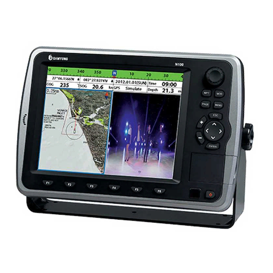
• Autopilot on your boat. The chart plotter can be connected to external devices with NMEA0183 and NMEA2000 interface and display information. Following are the examples. 1-2 Specification [NF100] GENERAL Category Detail 235mm(H) x 349mm(W) x 90mm(D) Size Display 10.4 inch, TFT color, 800X600 pixel... -
Page 9: Components
APA, APB, BWR, GGA, GLL, GSA, GSV, RMB, RMC, VTG, XTE, DBT, DPT, MTW, VHW, XDR NMEA 2000 Output +++Water Speed(128259), Water depth(128267), XTE(129283), NAV. data(129284), NAV. data(129285), COG & SOG(129026), GNSS position(129029), Water temp.(130310) 1-3 Components Part Number List NF100 N100 Display NF100-K N100-K Bracket N100-DB Cover N100–CC... -
Page 10: Getting Started
2 Getting Started 2-1 Installation The chart plotter is supplied with bracket and flush mounting kit. You can choose a method of installation according to your preference. 2-1-1 Bracket Mounting Find the appropriate place to install considering GPS Chart plotter’s weight and user convenience. - Page 11 ④ ⑥ ① ② ③ ⑤ ⑧ ⑦ ① Plotter : Displays plotter window no matter where you are at. ② Fishfinder : Displays the Fishfinding window. ③ Data : Displays the Data window ④ Highway : Displays the Highway window. ⑤3D map setting menu : Displays the menu that allows you to view map in 3D, and user may set to the setting he wishes to use..
-
Page 12: Navionics Sd Card, Usb
[REM-350] ※ Remote control(REM-350) is Option device 2-3 NAVIONICS SD Card, USB This section explains how to insert and remove the NAVIONICS SD Card and USB. Inserting SD Card 1 You have two slots for SD card as shown in ①, when you insert to the left slot, face the label to left as shown in ③... -
Page 13: Chart Selection
2-4 Chart Selection You may choose to display one map from 2 (NAVIONICS, SAMYUNG MAP) NAVIONICS SD Card is optional, and is not supplied Follow the instruction for selection of map. with the equipment. User may 1 Hold down to purchase it and use it. -
Page 14: Compass
2-7 Compass The chart plotter computes compass direction To turn the compass off and on from the constellation of GPS satellites. It is 1 Press and select Data bar. shown at the top of screen. 2 Check compass. For easy recognition, there is a compass needle at top right side. -
Page 15: Multi Window Display
2-8 Multi Window Display Chart plotter can display up to four Changing window size windows at a time. 1 Press and select Split icon on bottom 2 Press to change the size of the windows Removing the window 1 Press and hold down to select a window you wish to remove. -
Page 16: User Line Drawing
Active window If more than one windows are displayed, the active window has blue border around it. If you wish to activate other window, press and hold It is important to know which window is active as each window’s function can be used from the multi-screen. -
Page 17: General Operation
3 General Operation 3-1 Power on and off Power on Power off Press and hold until the display Press and hold . It will start a count shows the start up page. Press down. If you do not release the button accept the warning screen. -
Page 18: Main Window
3-3 Main window To display the one window from the main page, press and select function you wish to show. Note 1 Some function icons require optional units and sensors Echo Sounder Video Chart Highway Data Waypoint Routes Tide Satellites Navtex Engine Errors User Guide... -
Page 19: Chart
3-4 Chart Chart window shows all the navigational relevant data of S-MAP and NAVIONICS (buoys, lights, cables, depth sounding, marinas, tide station) 3-4-1 Chart Window To go to the Chart window: ① Data bar. You may change the data Press and select Chart icon. -
Page 20: Samyung Map Search
3-4-5 SAMYUNG Map Search This function is available when it has been set for SAMYUNG map to be displayed. This function is not available To find port & service: with NAVIONICS. -
Page 21: Going To A Waypoint Or To A Point On The Chart
3-4-8 Going to a waypoint or to a point on the chart A waypoint is a particular location on a Cancelling Navigating voyage whether it is a starting, 1 Press and select chart icon. intermediate or destination point. A 2 Press and select Cancel Goto. -
Page 22: Projected Course
3-4-11 Projected course The projected course shows you how far it can go at given time and speed. Projected position This function is useful to avoid collision with other vessels. Boat’s projected course Boat position 3-4-12 Finding a chart symbol From the chart, when you hold down to , the Mark window will show. -
Page 23: Video
3-5 VIDEO You may use the media cable to connect with CCTV, S-VIDEO or download the files from SD Card, USB to play it on the video function. To activate the video function, follow the instruction in order 1 Hold down to to select the system setting category. -
Page 24: Sonar
3-6 Sonar It is possible to use the Sonar function when it is connected to the transducer. Follow the following steps to activate the Sonar function. 1 Press and hold, select System Setting 2 Select additional component and select Sonar. 3 Press and press Then select Sonar. -
Page 25: Single Or Dual Frequency Fish Finding
3-6-3 Single or Dual Frequency Fish finding Sonar frequencies The display is useful for comparing the The unit has dual frequency, 200kHz and same picture with two different 50kHz to detect various bottom conditions. frequencies. 1 Press , select Frequency. 2 Select one frequency High frequency (200kHz ) The higher ultrasonic signal, the better is... -
Page 26: Gain
[When the set depth is too low] [When the set depth is too high] 3-6-5 Gain The Gain Mode To change a mode, The gain is a signal strength received from 1 Press , select Gain. the transducer and the threshold is the 2 Select a mode. -
Page 27: Sonar Window Display
3-6-6 Sonar window display Five sonar display windows are available Split A-Scope: Display Sonar history and and each display window has unique echo strength (see section 3-5-11) characteristics. Select a display window You can change the split ratio if the depending on your needs. -
Page 28: Split Bottom
3-6-9 Split bottom Split bottom display provides a normal picture on the right half and a selectable range over and below the bottom line is expanded onto the left half of the screen. This mode is useful for detecting bottom fishes. -
Page 29: Split 50/200
3-6-10 Split 50/200 The 50 kHz display appears on the left and the 200 kHz appears on the right. This dual frequency display is very useful for comparing the same scanning with two different frequencies. 3-6-11Split A-Scope This display shows echoes at each transmission with amplitudes and colors proportional to their intensities;... -
Page 30: Highway
3-7 Highway The Highway window shows a 3D view of the vessel traveling through the water when navigating to a destination point. To go to the Highway window, press and select Highway icon. The Highway window shows: ① Compass. ② Data bar. ③... -
Page 31: Waypoints
3-9 Waypoints A waypoint is a particular location on a voyage whether it is a starting, intermediate or destination point. A waypoint is the simplest piece of information the unit requires to get you to a destination in the shortest distance possible. This unit can save up to 10,000 waypoints. -
Page 32: Sort Waypoints
3-9-6 Sort Waypoints 3-9-7 Deleting all waypoints To change the order of displayed waypoint 1 In the waypoints window, press list: select Delete all. 1 Press and select Sort by. 2 Select Yes. 2 Select a sort type. User Guide... -
Page 33: Routes
3-10 Routes A trip from one place to another often involves several course changes, requiring a series of waypoints which you navigate to, one after another. The sequence of waypoints leading to the final destination is called a route. The unit can automatically advance to the next waypoint on a route. -
Page 34: Managing A Route From The Route Window
3-10-2 Managing a route from the route window Creating a rout from the route window Deleting a waypoint in the waypoint list 1 To go to the Route window, press 1 Highlight a waypoint you want to delete in the waypoint list. and select the Route icon 2 Press and select Remove. - Page 35 ⑤ ④ ③ ② ① ⑥ User Guide...
-
Page 36: Tides
⑧ Tide chart. - Next day: automatically set the date of ⑨ Tide height. today. In case of SAMYUNG MAP is - Prev day: automatically set the date of yesterday already set, it 2 Press to return to the window... -
Page 37: Ais
3-13 AIS AIS is an Automatic Identification System for identification and localization of boat. AIS provide a means for boats to exchange and share boat data including identification, position, course, etc. This information can be displayed on the screen of you unit. AIS is intended to assist you to monitor other boats movements to improve safety and prevent collision. - Page 38 User Guide...
-
Page 39: Dsc
3-14 DSC This feature requires connection to optional DSC VHF radio. DSC window shows the distress and poll information received from other vessel through DSC VHF radio. 1 Press and Hold Menu, then select the system configuration. 2 Select the optional components and select DSC 3 Press , press in the screen and select DSC. -
Page 40: Poll
3-14-2 Poll Deleting a poll Poll 1 Highlight a received distress call you want A compatible radio with the unit can request to delete. the position of other DSC VHF radio equipped 2 Press and select Delete. vessels around its position. When the position of a vessel is received, the location is displayed on the screen and it is logged into Deleting all poll... -
Page 41: Navtex
3-15 Navtex NAVTEX is an international automated direct Deleting a message printing service for delivery of navigational 1 Move the cursor to a message you want to and meteorological warnings and forecast, as delete. well as urgent marine safety information. 2 Press and select Delete. -
Page 42: Settings
4 Settings The system menu mainly consists of settings which do not require frequent adjustment. To go to system menu, press and hold then select the icon you want. ① System Configuration. ② SONAR. ③ Communication. ④ GPS. ⑤ Track & Log. ⑥... -
Page 43: Chart Settings
4-2 Chart settings To go to the chart settings: 1 Press and hold 2 Select the chart icon. NAVIONICS S-MAP Projected course: Display the Projected 4-2-1 Rotation course in given set time. Three types of display presentations are CDI scale: Set CDI (Course Deviation provided. -
Page 44: Map Datum
Cable on or off Applying a map shift Name: Turns the displaying of area name on 1 In the Chart setup menu, press and hold or off and select Chart icon. Mark Attribute: Turns the displaying of 2 Select Map shift to ON. Mark Attribute on or off 3 Move cursor to the actual position on the Sea Sector No: Turns the displaying of Sea... -
Page 45: Frequency
4-3-1 Frequency Fish sensitivity You can select a sonar frequency among 200 Select the minimum strength fish echo that kHz, 50 kHz or Mixed. will be displayed as a fish symbol. 4-3-2 Palette 4-3-6 Advance Settings Palettes are used to enhance the visibility of Interference filter: Interference from other the display depending on the surrounding equipment operating nearby or on your boat... -
Page 46: Gps Settings
4-4 GPS Settings To go to the GPS settings: 1 Press and hold 2 Select the GPS icon. When the GPS device is connected properly, the GPS settings provide the access to GPS functions and features connected with the satellites information used for further navigational information. -
Page 47: Track
4-5-1 Track 4-5-2 Log Reset trip dist Shows you the trip distance. If you select this Record option it resets the trip distance. Off: Stop a recording of Track Reset total dist 1 to 10 (select a track number): Start a Show you the total trip distance. -
Page 48: Memory Settings
4-6 Memory Settings To go to the memory settings: 1 Press and hold 2 Select the Memory icon. A user card is an option SD card which you need to purchase additionally. Before you use a user card it must be formatted. Note that formatting a user card erases all saved data. -
Page 49: Display Filter
4-7-1 Display Filter There are a couple of methods to filter AIS Filter by speed : Vessels with speed below vessel in this unit as below. the set value are filtered. Filter by Type : The type of vessel which is Show Dangerous Only : When this option selected will not be displayed on the chart. -
Page 50: Deep
A warning message with beep sound is displayed when an alarm condition is met by user setting. Press to clear the alarm. However, the alarm will be displayed again when the alarm condition occurs again. The unit provides alarms for various functions. 4-8-1 Deep 4-8-6 Navigation alarms Trigger an alarm when the depth value... -
Page 51: Other Settings
4-9 Other settings Press long then select Others: 4-9-1 Simulate Select the Port(NMEA0183-Por1, Simulate :Turn the simulate mode on or off. NMEA0183-Port2, NMEA2000) and Mode : See 2-5 Simulate Mode. Transmission speed and select the Speed : The simulated boat speed to use. demanded output information. -
Page 52: Connections
5 CONNECTIONS Accurate installation highly affects the performance of this equipment. You must read the manual on installation, antenna and other equipment information before installation process. For information on the additional equipment, contact SAMYUNGENC and check. 5-1 OPTIONAL PART Optional sense and equipment •... - Page 53 Number of Pin Color Description BLACK Enter -POWER BROWN WHITE NMEA0183 output BLUE NMEA0183 input +POWER input, 11 to 36V DC ORANGE YELLOW NMEA0183 GND GREEN output the external alarm, maximum 30V DC 200mA [SONAR] [REMOTE] Number Description Number Description of pin of pin SONAR+...
-
Page 54: Connection
5-2 CONNECTION GPS Chart plotter has the connection device to connect with the NMEA equipment like power supply, GPS antenna, AIS receiver, auto pilot device and digital equipment. *Warning: Check that the power supply cable does not get connected to the REMOTE Connector or the DATA connector. -
Page 55: Data
INPUT PIN No. : 4 (Data in) OUTPUT PIN No. : 3 (Data out) NMEA 0183 PIN No. : 7 (GND) NMEA 0183 PIN No. : 7 (GND) DSC VHF radio • Equipment may transmit the GPS location Refer to the above NMEA 0183 picture to and navigational information to the auto install the optional DSC VHF radio pilot equipment or other equipment. -
Page 56: Set Up And Test
3-4 Map 3-4-1 Map display 3-4-2 Longitude and Latitude 3-4-3 Chart Scale 3-4-4 NAVIONICS Search 3-4-5 SAMYUNG MARP Search 3-5-6 Symbol and information 3-4-7 Navigational information 3-4-8 Get to waypoint or point in a chart 3-4-9 Follow the route 3-4-10 Distance and bearing calculator... - Page 57 3-5 Video 3-5-1 Option 3-6 Fishfinder 3-6-1 Screen setting 3-6-2 Mode 3-6-3 Single or dual frequency fish finding 3-6-4 Range 3-6-5 Gain 3-6-6 Fish finder 3-6-7 No division of window 3-6-8 Split enlargement or full screen zoom. 3-6-9 Enlarge lowland 3-6-10 Dual frequency display(50/200) 3-6-11 A-Scope display 3-7 Highway...
- Page 58 4-3 Sonar setting 4-3-1 Frequency 4-3-2 Palette 4-3-3 Scroll Speed 4-3-4 Font Size 4-3-5 Fish 4-3-6 Advance setting 4-3-7 Restore default 4-4 GPS Setting 4-4-1 GPS Source 4-4-2 DGPS Source 4-4-3 Static Navigation 4-4-4 Speed Filter 4-4-5 Course Filter 4-4-6 Lat/Lon d.p’s 4-4-7 Ship speed 4-4-8 Magnetic Variation 4-5 Track setting...
- Page 59 4-9 Other setting 4-9-1 simulation 4-9-2 Waypoint 4-9-3 GPS 4-9-4 Units 4-9-5 Comms 4-9-6 Time 4-9-7 Restore default 5. Device commection 5-1 Optional parts 5-2 Connection part 5-3 Power supply & DATA cable 5-4 Alarm equipment 5-5 GPS Antenna 5-5-1 external antenna 5-5-2 internal antenna 5-6 NMEA0183 5-7 DATA...
-
Page 60: System Maintenance
When it has salt water or dirt, use clean tissue or cloth to remove it. Do not use the chemical to remove it as it may remove the color of surface or the writings on it. ※ Always update the electronic chart (Samyung Map) User Guide... - Page 61 Diagnosis The chart explains the general symptoms of breakdown and solutions to it. User should not disassemble equipment. The attempt may degrade the function of equipment or shorten the life of it. Therefore you take it to the professional engineer (A/S Center) AS Center ☏...
- Page 62 N100/NF100 Installation 1. If not connected to AIS, Autopilot, DGPS (Interconnect to the Power Cable 8P) POWER CABLE (8P) GNB-400S 3. TX(WHITE) RX(BLUE) 4. RX(BLUE) TX(YELLOW) 7. GND(YELLOW) GND(WHITE) POWER EXT Power+RED DC+10~36V EXT Power-BLACK 2. When two equipment AIS and Autopilot are connected (Interconnect to the Data Connector LTW 8P)
- Page 63 User Guide...
- Page 64 1 YEAR WARRANTY Thank you for purchasing an SAMYUNG ENC product. This product has been thoroughly checked and is covered by the Samyung ENC’s warranty for defects in materials and workmanship under normal use from the date of purchase. This warranty provides for the free repair or replacement of defective parts from our Samyung ENC authorized dealer.
- Page 65 User Guide...
- Page 66 User Guide...
- Page 67 User Guide...
Need help?
Do you have a question about the Nf100 and is the answer not in the manual?
Questions and answers