Table of Contents
Advertisement
Quick Links
Advertisement
Table of Contents

Subscribe to Our Youtube Channel
Related Manuals for Samyung N430


Summary of Contents for Samyung N430
- Page 1 Installation and Operation Manual...
- Page 2 Installation and Operation Manual...
-
Page 3: Screen Cleaning Precautions
If too dry, the tissue won’t glide easily, and may damage the surface. If you require technical advice or assistance, contact your nearest samyung enc office or visit our website, www.samyungenc.com. Installation and Operation Manual... - Page 4 Installation and Operation Manual...
-
Page 5: Table Of Contents
1 Introduction ................9 1-1 General Information ................... 9 1-2 Specification ....................9 1-3 Packing List ....................10 1-4 Optional Accessories ................10 2 Getting Started ..............11 2-1 Installation ....................11 2-1-1 Bracket Mounting ................11 2-1-2 Flush Mounting .................. 11 2-2 Keys ...................... - Page 6 3-5-6 Sonar window display ................. 30 3-5-7 No plit ....................30 3-5-8 Split zoom and Full Screen zoom ............31 3-5-9 Split bottom ..................31 3-5-10 Split 50/200 ..................32 3-5-11 Split A-Scope ................... 32 3-6 Highway .................... 33 3-7 Gauges....................33 3-8 Waypoints ..................
- Page 7 4-2- Palette ....................47 4-2-3-1 General (NAVIONICS) ..............47 4-2-3-2 General(S-MAP) ................47 4-2-4-1 Land & Sea (NAVIONICS) ..............47 4-2-4-2 Land & Sea (S-MAP) ................ 48 4-2-5 Map datum ..................48 4-2-6 NMEA datum offset ................48 4-2-7 Map shift ................... 48 4-2-8 Restore default ..................
- Page 8 4-8-7 Restore default .................. 55 5 INSTALLATION ..............56 5-1 Options and Accessories ................56 5-2 Connections ....................57 5-3 Power / Data Cable .................. 57 5-4 GPS Antenna ..................... 57 5-4-1 External Antenna ................57 5-4-2 The Antenna by using NMEA ............... 58 5-5 Sonar ......................
-
Page 9: Introduction
Some functions require optional • AIS receiver units and sensors installed on your boat. • DSC VHF radio • Transducer & sensors • Autopilot 1-2 Specification [N430, NF430] GENERAL Category Detail Size 129 mm(H) x 183 mm(W) x 113.5 mm(D) Display 4.3 “Diagonal, TFT color, 480 x 272 pixels... -
Page 10: Packing List
1-3 Packing List Part number Item List N430 NF430 Display N430-E NF430-E Bracket N430-DB Display Cover Z8-2M-05 Bracket mounting screw N430-BP Protection Cover N430-CB User’s Manual(E) N430-ME Quick User Guide(E) N430-BE GPS Antenna Stand type Support 57745 GPS Antenna +... -
Page 11: Getting Started
2 Getting Started 2-1 Installation The chart plotter is supplied with bracket and flush mounting kit. You can choose a method of installation according to your preference. 2-1-1 Bracket Mounting Before installing ensure the area the bracket is mounted to is strong enough to support the weight of the GPS chart plotter. -
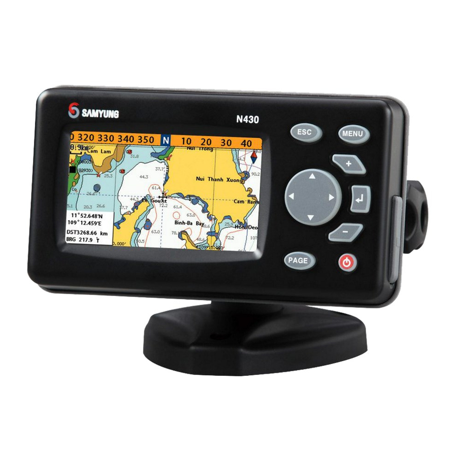
Page 12: Keys
2-2 Keys ESC – Exit from menu and return to previous menu or window. In chart window, it places own ship at center. (If press and hold ESC in chart window, you can access to track option) MENU – Show available options of current window. -
Page 13: Navionics Sd Card
User can purchase it A user can select a map as follow instruction, themselves or contact Chart Selection Samyung agent for 1 Press and hold purchasing. 2 Select the system setting icon. 3 Select Chart then a chart you prefer. - Page 14 Data bar displays useful navigation Selecting the Data bar size information at the top of the display. 1 Press and select Data bar. 2 Select Data bar then Data bar size. 3 Select the desired size of data bar. [Large] Displaying Data bar 1 Press and select Data bar.
-
Page 15: Compass
2-7 Compass The chart plotter computes compass direction To turn the compass off or on: from the constellation of GPS satellites. For 1 Press and select Data bar. the GPS chart plotter to compute direction 2 Select Compass. the vessel must be moving through the water.. -
Page 16: Multi Window Display
2-8 Multi Window Display The Chart plotter can display up to four windows at the same time. Changing window size 1 Press and select Split icon on bottom. 2 Press to change the height of the windows if there is only two windows. If the unit is displaying more that three windows, press change the height of the windows. - Page 17 Active Window To distinguish an active window among windows, an orange border indicates the active window. To change the active window to the next window, press and hold It is important to notice which screen is on due to the multi screens which can be used each screen’s function.
-
Page 18: General Operation
3 General Operation 3-1 Power on and off Manual power on Manual power off Press and hold until the display shows Press and hold for 5 seconds. A counter the start up page. When the Warning screen timer appears on the screen, if you release appears, press to accept. -
Page 19: The
3-3 The page window Press to show the page window and select a function icon you want to display. Note 1 Some function icons require optional units and connected sensors. 2 If you press one more time in the main window, favorite window is displayed. - Page 20 Highway Sonar Chart Chart Routes Waypoints Data Tides Satellite Engine Faults Navtex Engine Faults Installation and Operation Manual...
-
Page 21: Chart
3-4 Chart The Chart window mainly shows all relevant navigation data available on your preloaded maps, including buoys, lights, cables, depth soundings, marinas, and tide station in an overhead view. 3-4-1 Chart window To go to the Chart window: ① Data bar. To turn the data off or on or to •... -
Page 22: Latitude And Longitude
3-4-2 Latitude and longitude Latitude and longitude coordinates define a Info position on earth and can be displayed in Latitude: Angular distance North or South of data bar. the equator measured by lines encircling the In the data bar, own ship position is shown earth parallel to the equator in degrees from as below: 0°... -
Page 23: S-Map Search
3-4-6 S-Map search This function is available when NAVIONICS SD card is inserted and NAVIONICS is selected. To find port & service 1 Press NAVIONICS Chart does not 2 Select Find then Port. support this function. 3 Press to select a port then (See 2-4 for chart selection) 4 After searching process, select a nearest port in the list then the cursor will place... -
Page 24: Going To A Waypoint Or To A Point On The Chart
3-4-9 Going to a waypoint or to a point on the chart A waypoint is a particular location on a Cancelling navigating voyage whether it is a starting, intermediate 1 Press and select the Chart icon. or destination point. A waypoint is the 2 Press and select Cancel Goto. -
Page 25: Distance And Bearing Calculator
3-4-11 Distance and bearing calculator The unit can show the bearing and the length Saving as a route of leg and the total distance of legs. 1 Once you set all the legs, press select Save. Setting Legs 2 Enter a route name by pressing 1 In the chart window, press to select a letter then press for next... -
Page 26: Tracks & Log Settings In The Chart Window
3-4-14 Tracks & Log Settings in the chart window For tracks & log setting in the chart . (See 2-4 window, press and hold for Track & Log Settings) Installation and Operation Manual... -
Page 27: Sonar
3-5 Sonar It is available to use a sonar function when this equipment is connected to an depth transducer. Please refer the following process to use Sonar. 1 Press button longer and set system section. 2 Please add the page and select Sonar. 3 Press button and press button on the main... -
Page 28: Single And Dual Frequency Fish Finding
3-5-3 Single and Dual frequency fish finding Sonar frequencies The display is useful for comparing the same The unit has dual frequency, 200kHz and picture with two different frequencies. 50kHz to detect various bottom conditions. To select the sonar frequency in sonar window: 1 Press , select Frequency. -
Page 29: Gain
[When the set depth is too low] [When the set depth is too high] 3-5-5 Gain The gain menu To change a mode, The gain is a signal strength received from 1 Press , select Gain. the transducer and the threshold is the level 2 Select a mode. -
Page 30: Sonar Window Display
3-5-6 Sonar window display Five sonar display windows are available and Split A-Scope: Display Sonar history and each display window has unique echo strength (see section 3-5-11) characteristics. Select a display window You can change the split ratio if the window depending on your needs. -
Page 31: Split Zoom And Full Screen Zoom
3-5-8 Split zoom and Full Screen zoom Split zoom Bottom lock Split zoom mode expands selected area of If Bottom lock is on, the zoom depth (the the single frequency by VRM(Variable Range depth of the zoom section) is adjusted Mark). -
Page 32: Split 50/200
3-5-10 Split 50/200 The 50 kHz display appears on the left and the 200 kHz appears on the right. This dual frequency display is very useful for comparing the same scanning with two different frequencies. *NF430 is a 200KHZ only. 3-5-11 Split A-Scope This display shows echoes at each transmission with amplitudes and colors... -
Page 33: Highway
3-6 Highway The Highway window shows a 3D view of the vessel traveling through the water when navigating to a destination point. To go to the Highway window, press and select Highway icon. The Highway window shows: ① Compass. ② Data bar. ③... -
Page 34: Waypoints
3-8 Waypoints A waypoint is a particular location on a voyage whether it is a starting, intermediate or destination point. A waypoint is the simplest piece of information the unit requires to get you to a destination in the shortest distance possible. This unit can save up to 10,000 waypoints. -
Page 35: Deleting A Waypoint
3-8-4 Deleting a waypoint To delete a waypoint from the chart Deleting a waypoint from the waypoints window window 1 Move the cursor to the waypoint you want 1 Move cursor key to highlight a waypoint to delete. (If you move the cursor on the you want to delete. -
Page 36: Routes
3-9 Routes A trip from one place to another often involves several course changes, requiring a series of waypoints which you navigate to, one after another. The sequence of waypoints leading to the final destination is called a route. The unit can automatically advance to the next waypoint on a route. -
Page 37: Managing A Route From The Route Window
3-9-2 Managing a route from the route window Creating a rout from the route window Deleting a waypoint in the waypoint list 1 To go to the Route window, press 1 Highlight a waypoint you want to delete in the waypoint list. and select the Route icon 2 Press and select Remove. -
Page 38: Satellites
3-10 Satellites 3-10-1 Satellite information Acquiring GPS signals When the unit is first turned on it will take ① Ship’s Coordinates. some time for the GPS signal acquiring. After ② Time received GPS satellites. signals are received, the unit will ③... -
Page 39: Tides
- Set date: manually set a date. ⑨ Tide height. - Today: automatically set the date of today. In case of SAMYUNG MAP is - Next day: automatically set the date of already set, it today. (Please refer to 2-4 how to... -
Page 40: Ais
3-12 AIS AIS is an Automatic Identification System for identification and localization of boat. AIS provide a means for boats to exchange and share boat data including identification, position, course, etc. This information can be displayed on the screen of you unit. AIS is intended to assist you to monitor other boats movements to improve safety and prevent collision. - Page 41 [AIS Vessel Information -1] AIS Vessel List] [AIS Vessel Information -2] [AIS Vessel Safety message] Installation and Operation Manual...
-
Page 42: Dsc
3-13 DSC This feature requires connection to optional DSC VHF radio. DSC window shows the distress and poll information received from other vessel through DSC VHF radio. 1 Press and Hold Menu, then select the system configuration. 2 Select the optional components and select DSC 3 Press ESC and press DISPLAY from the top page then select DSC. -
Page 43: Poll
3-13-2 Poll Deleting a poll Poll 1 Highlight a received distress call you want A compatible radio with the unit can request to delete. the position of other DSC VHF radio equipped 2 Press and select Delete. vessels around its position. When the position of a vessel is received, the location is displayed on the screen and it is logged into Deleting all poll... -
Page 44: Navtex
3-14 NAVTEX NAVTEX is an international automated direct Deleting a message printing service for delivery of navigational 1 Move the cursor to a message you want to and meteorological warnings and forecast, as delete. well as urgent marine safety information. 2 Press and select Delete. -
Page 45: Settings
4 Settings The system menu mainly consists of settings which do not require frequent adjustment. To go to system menu, press and hold then select the icon you want. ① System Configuration. ② Chart. ③ Communication. ④ GPS. ⑤ Track & Log. ⑥... -
Page 46: Chart Settings
4-2 Chart Settings To go to the chart settings: 1 Press and hold 2 Select the chart icon. Installation and Operation Manual... -
Page 47: Rotation
4-2-1 Rotation These objects have been obtained from other Three types of display presentations are sources and then merged to the electronic provided. The default is heading up. charts in order to provide more information North up: North is at the top of the display. useful for the navigation. -
Page 48: Land & Sea (S-Map)
Sounding min: Set the minimum depth limit 4-2-7 Map shift to show depth sounding, bathymetric lines Sometimes current position of own ship does and depth area. not match with the current location on the Sounding max: Set the maximum depth chart. -
Page 49: Gps Settings
4-3 GPS Settings To go to the GPS settings: 1 Press and hold 2 Select the GPS icon. When the GPS device is connected properly, the GPS settings provide the access to GPS functions and features connected with the satellites information used for further navigation 4-3-1 GPS Source 4-3-5 Course Filter Select a source of GPS signals... -
Page 50: Track & Log Settings
4-4 Track & Log Settings To go to the tracking and long settings: 1 Press and hold 2 Select the track & log icon. The unit has the capability to store 10 individual tracks and record up to 15,000 track points. Before using the track function you will need to setup the track function that suits your boat. -
Page 51: Memory Settings
4-5 Memory Settings To go to the memory settings: 1 Press and hold 2 Select the Memory icon. A user card is an option SD card which you need to purchase additionally. Before you use a user card it must be formatted. Note that formatting a user card erases all saved data. -
Page 52: Format
4-5-4 Format 4-5-5 Screen Snap Shot Erase all data in the user card. Format the To take the snap shot of current screen, press user card before using it. twice. To save the captured image, press and select Save or Save all to save the captured images on the user card. -
Page 53: Display Filter
4-6-1 Display Filter There are a couple of methods to filter AIS Filter by speed : Vessels with speed below vessel in this unit as below. the set value are filtered. Filter by Type : The type of vessel which is Show Dangerous Only : When this option selected will not be displayed on the chart. -
Page 54: Alarm Settings
4-7 Alarm Settings Press long then select Alarms:: A warning message with beep sound is displayed when an alarm condition is met by user setting. Press to clear the alarm. However, the alarm will be displayed again when the alarm condition occurs again. The unit provides alarms for various functions. 4-7-1 Deep 4-7-6 Navigation alarms Trigger an alarm when the depth value... -
Page 55: Others
4-8 Others Press long then select Others: 4-8-1 Simulate 4-8-6 Time Simulate :Turn the simulate mode on or off. Local offset : The time information supplied Mode : See 2-4 Simulate Mode. by the GPS satellites is in UTC (Universal Speed : The simulated boat speed to use. -
Page 56: Installation
Correct installation is important to the performance of the unit. It is vital to read the entire installation section of this manual and the documentation that comes with the antenna and any other units before starting installation. For further information, please contact Samyung ENC. 5-1 Options and Accessories Optional sensors and instruments •... -
Page 57: Connections
5-2 Connections The GPS chart plotter has connectors that are used to connect to the power supply, GPS antenna and to NMEA devices such as VHF’s AIS receivers, digital instruments and autopilots. 5-3 Power / Data Cable Power • Connect each equipment as the below picture for Power. Power / Data Cable PIN No : 5 FUSE 2A... -
Page 58: The Antenna By Using Nmea
WAAS or EGNOS are not antenna. available. Such a DGPS antenna has both a GPS receiver and a beacon receiver, and it For more information, contact Samyung ENC. automatically applies the beacon correction to the GPS position. 5-5 Sonar Sonar •... -
Page 59: Nmea 0183
0183(2) IN. APB, APA and VTG sentences For information on sending NMEA data to Other NMEA instruments the instrument, contact Samyung ENC. NMEA is an industry standard for During setup to send NMEA data to other interconnecting instruments. The chart plotter instruments, set NMEA out and specify the can be connected to other NMEA instruments. - Page 60 1 YEAR WARRANTY Thank you for purchasing an SAMYUNG ENC product. This product has been thoroughly checked and is covered by the Samyung ENC’s warranty for defects in materials and workmanship under normal use from the date of purchase. This warranty provides for the free repair or replacement of defective parts from our Samyung ENC authorized dealer.
- Page 61 Installation and Operation Manual...
- Page 62 Installation and Operation Manual...
- Page 63 Installation and Operation Manual...
Need help?
Do you have a question about the N430 and is the answer not in the manual?
Questions and answers
Power connection
The power connection method for the Samyung N430 involves using the Power/Data cable. Pin 5 of this cable is for + power input (10 to 35 V DC), and Pin 1 (black) is ground. A 2A fuse should be used in the power line.
This answer is automatically generated