Table of Contents
Advertisement
Quick Links
Advertisement
Table of Contents

Subscribe to Our Youtube Channel
Related Manuals for Samyung AIS-50N


Summary of Contents for Samyung AIS-50N
- Page 2 Installation and Operation Manual...
-
Page 3: Industry Canada
Installation: If installation is not correct, the unit can not perform at its designed potential. If in doubt, consult your Samyung ENC dealer. Ensure that any holes made are in a safe position and will not weaken the boat’s structure. If in doubt, consult a qualified boat builder. -
Page 4: Screen Cleaning Precautions
If too dry, the tissue won’t glide easily, and may damage the surface. If you require technical advice or assistance, contact your nearest Samyung ENC office or visit our website, www.samyungenc.com. Installation and Operation Manual... -
Page 5: Table Of Contents
1 Introduction 1-1 Summary ................9 1-2 AIS Technology Summary ............9 1-3 Specification ................. 11 1-4 Packing List ................12 1-5 Optional Accessories ............. 12 2 Getting Started 2-1 Mounting the Unit ..............13 2-1-1 Bracket Mounting ................13 2-1-2 Flush Mounting .................. - Page 6 4-7-7 Chart symbols and information ............30 4-7-8 Introduction to navigating ..............30 4-7-9 Going to a waypoint or to a point on the chart ........31 4-7-10 Following a route ................31 4-7-11 Goto Key ..................31 4-7-12 Distance and bearing calculator ............32 4-7-13 COG ....................
- Page 7 5-2-3-2 General(S-MAP) ................47 5-2-4-1 Land & Sea (NAVIONICS) ..............47 5-2-4-2 Land & Sea (S-MAP) ................ 47 5-2-5 Map datum ..................47 5-2-6 NMEA datum offset ................48 5-2-7 Map shift ................... 48 5-2-8 Restore default .................. 48 5-3 Communication setup ........... 49 5-3-1 NMEA 2000 ..................
- Page 8 5-9-6 Time ....................56 5-9-7 Restore default .................. 56 5-9-8 Calendar ................... 56 6 INSTALLATION 6-1 Options and Accessories ............57 6-2 Connections ................. 57 6-3 Power/data cable ..............59 6-4 Alarm .................. 60 6-5 VHF antenna installation ............61 6-6 GPS antenna ................
-
Page 9: Summary
1 Introduction 1-1 Summary AIS is a spearhead equipment to provide AIS-50N has high efficiency AIS Class B. It voyage information such as ship’s position, provides plotter functions, needed in voyage. course, speed, etc. real time. This is to Some functions can be used with... - Page 10 Intervals of Information renewal are shown by table, according to ship status, classified by two Classes of AIS. Ship status (A Class) Interval Under speed 3 knots, in anchorage or moorage 3min. Over speed 3 knots, in anchorage or moorage 10sec.
-
Page 11: Specification
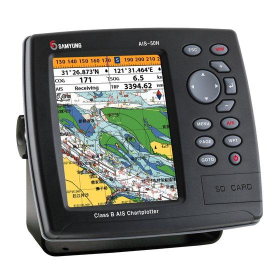
1-3 Specification [AIS-50N] GENERAL Category Detail Size 164 mm(H) x 183 mm(W) x 92.5 mm(D) Display 5.6” diagonal, TFT color, 480 x 640 pixels. Supply voltage 10 to 34 V DC Supply current 13.8 V 24 V 1A - AIS receiving by mode 0.5A - AIS receiving by mode... -
Page 12: Packing List
1-4 Packing List Item List Part number Display AIS-50N-E Bracket N560-DB Display Cover N560-CB Protection Cover N560-CC Power Cable LTW-2000-8 Bracket mounting screw N560-BP Flush mount Kit (Including scr w) N560-TK Cable tie N560-CK User’s Manual(Eng) AIS-50N-ME 1-5 Optional Accessories... -
Page 13: Getting Started
2 Getting Started 2-1 Mounting the Unit The chart plotter is supplied with bracket and flush mounting kit. You can choose a method of installation according to your preference. 2-1-1 Bracket Mounting Select the position, considering weight of equipment, conveniences, etc before installing. Display installing: 1 Gripping display, find both connecting joints between display &... -
Page 14: Keys
2-2 Keys – Exit from menu and return to previous menu or window. In chart window, it places own ship at center. SRM – If you push button long, SRM function works. (Refer to 2-5) CURSOR – Moves the cursor on the display screen. -
Page 15: Navionics Secure Digital (Sd) Card
2-3 NAVIONICS Secure Digital (SD) Card This section provides instructions for inserting and removing NAVI01NICS SD card procedure. Inserting the SD Card 1 Hold the SD card so that you can see the NAVIONICS label. 2 Open the door, gently push the SD card into the slot;... -
Page 16: Srm(Safety Related Message)
If you push SRM button long, counter is GPS signals. displayed. In 3 seconds (3->2->1), setup message is transmitted. SRM function of AIS-50N is made to meet 62287-1 Message 14 standard of IEC(International. Electrotechnical Commission) Users can set up SRM, which they want, referring to 3-5-1. -
Page 17: Ais Function Explanation
3 AIS Function Explanation 3-1 Screen configuration Opening screen is the vessel list of AIS-50N, which shows the distances & directions information from own vessel, utilizing received information from other vessels. Own vessel information Using direction keys, you can check the static Information, voyage information, GNSS antenna information of own vessel. -
Page 18: Screen Change
3-3 Vessel list Opening screen is the vessel list of AIS-50N, which shows the distances & directions information from own vessel, utilizing received information from other vessels. : Pushing button, you can check vessel name or MMSI information. -
Page 19: Own Vessel / Other Vessel Information
3-4 Own vessel / other vessel information Using own vessel / other vessel information, user can check the static Information, voyage information, GNSS antenna information of own vessel or other vessels easily. Own vessel information 1 Check own vessel information, pushing ①... -
Page 20: Message
3-5-1 Message Receiving message You can check Safety Related Message, Voyage Related Message, which AIS base station or other vessels transmit. Receiving message is checked as follows. 1 Selecting receiving message item, push 2 Selecting the message, use wants to Region area list check, push Among Voyage Related Messages, AIS base... -
Page 21: Initial Setup
Sensor information Sensor information are checked as follows. You can check the status of sensor, 1 After selecting sensor information item, Input to AIS in voyage. push ► GNSS : Check GPS receiving status 2 Check the status of sensor. ►... -
Page 22: General Operation
2 Select the system setting icon. can be used. Please 3 Select Chart then a chart you prefer. contact your nearest Samyung ENC office for purchasing the NAVI01NICS 4-2 Simulate Mode Simulate Mode is great for practicing the actual use of a product when the satellites signals and internal alarms are not available. -
Page 23: Compass
Setting the data displayed in data bar [Large] 1 Press and select Data bar. 2 Select Data bar then Data bar setup. 3 Move the cursor key to highlight the data field you want to change then press 4 Select Data type. 5 Select a desired data you want to display in the field then press [Small]... -
Page 24: Multi Window Displays
4-5 Multi window displays The Chart plotter can display up to four windows at the same time. Changing window size 1 Press and select Split icon on bottom. 2 Press to change the height of the windows if there is only two windows. If the unit is displaying more that three windows, press change the height of the windows. - Page 25 The active window To distinguish an active window among windows, an orange border indicates the active window. To change the active window to the next window, press and hold Favorite displays The most commonly used windows are called favorite displays and up to six favorite windows can be saved.
-
Page 26: The
4-6 The page window Press to show the page window and select a function icon you want to display. Note 1 Some function icons require optional units and connected sensors. 2 If you press one more time in the main window, favorite window is displayed. - Page 27 Highway Data Chart Satellite Routes Waypoints Tides Engine Faults Navtex Installation and Operation Manual...
-
Page 28: Chart
4-7 Chart The Chart window mainly shows all relevant navigation data available on your preloaded maps, including buoys, lights, cables, depth soundings, marinas, and tide station in an overhead view. 4-7-1 Chart window To go to the Chart window: ① Data bar. To turn the data off or on or to •... -
Page 29: Latitude And Longitude
4-7-3 Latitude and longitude Latitude and longitude coordinates define a position on earth and can be displayed in Info data bar. Latitude: Angular distance North or South of In the data bar, own ship position is shown the equator measured by lines encircling the as below: earth parallel to the equator in degrees from 47°... -
Page 30: S-Map Search
4-7-6 S-Map search This function is available when NAVI01NICS SD card is inserted and NAVI01NICS is selected. To find port & service 1 Press NAVI01NICS Chart does not 2 Select Find then Port. support this function. 3 Press to select a port then (See 4-1 for chart selection) 4 After searching process, select a nearest port in the list then the cursor will place... -
Page 31: Going To A Waypoint Or To A Point On The Chart
4-7-9 Going to a waypoint or to a point on the chart A waypoint is a particular location on a voyage whether it is a starting, intermediate or destination point. A waypoint is the simplest piece of information your equipment requires to get you to a destination. -
Page 32: Distance And Bearing Calculator
4-7-12 Distance and bearing calculator The unit can show the bearing and the length Saving as a route of leg and the total distance of legs. 1 Once you set all the legs, press select Save. Setting Legs 2 Enter a route name by pressing 1 In the chart window, press to select a letter then press for next... -
Page 33: Highway
4-8 Highway The Highway window shows a 3D view of the vessel traveling through the water when ① navigating to a destination point. ② To go to the Highway window, press and select Highway icon. ③ The Highway window shows: ①... -
Page 34: Waypoints
4-10 Waypoints A waypoint is a particular location on a voyage whether it is a starting, intermediate or destination point. A waypoint is the simplest piece of information the unit requires to get you to a destination in the shortest distance possible. This unit can save up to 10,000 waypoints. -
Page 35: Deleting A Waypoint
4-10-4 Deleting a waypoint To delete a waypoint from the chart Deleting a waypoint from the waypoints window window 1 Move the cursor to the waypoint you want 1 Move cursor key to highlight a waypoint to delete. (If you move the cursor on the you want to delete. -
Page 36: Routes
4-11 Routes A trip from one place to another often involves several course changes, requiring a series of waypoints which you navigate to, one after another. The sequence of waypoints leading to the final destination is called a route. The unit can automatically advance to the next waypoint on a route. -
Page 37: Managing A Route From The Route Window
4-11-2 Managing a route from the route window Creating a rout from the route window Deleting a waypoint in the waypoint list 1 To go to the Route window, press 1 Highlight a waypoint you want to delete in the waypoint list. and select the Route icon 2 Press and select Remove. -
Page 38: Satellites
4-12 Satellites 4-12-1 Satellite information Acquiring GPS signals ① Ship’s Coordinates. When the unit is first turned on it will take ② Time received GPS satellites. some time for the GPS signal acquiring. After ③ Date received GPS satellites. signals are received, the unit will ④... -
Page 39: Tides
4-13 Tides The Tides window is useful for boaters that The tides window shows data for the are concerned about the height of the water chosen date or by fisherman that wish to know the tide and moon phase of a specific date. ①... -
Page 40: Ais
This information can be displayed on the screen of you unit. AIS is intended to assist you to monitor other boats movements to improve safety and prevent collision. AIS functions require an optional AIS unit to be installed. Contact your nearest Samyung ENC dealer for more details or visit at www.samyungenc.com. - Page 41 [AIS Vessel Information -1] [AIS Vessel List] [AIS Vessel Information -2] [AIS Vessel Safety message] Installation and Operation Manual...
-
Page 42: Dsc
4-15 DSC This feature requires connection to optional DSC VHF radio. DSC window shows the distress and poll information received from other vessel through DSC VHF radio. To go to the DSC windows: 1 Press , select DSC icon. 2 Select one of two tabs: Distress or Poll. 4-15-1 distress During a distress situation, a vessel that is Tip : When receiving a Distress call from... -
Page 43: Poll
4-15-2 Poll Poll Deleting all poll A compatible radio with the unit can request 1 Press and select Delete all. the position of other DSC VHF radio equipped vessels around its position. When the position Tip: Even though you delete a DSC call, of a vessel is received, the location is the DSC waypoints still exist. -
Page 44: Navtex
4-16 NAVTEX NAVTEX is an international automated direct Deleting a message printing service for delivery of navigational 1 Move the cursor to a message you want to and meteorological warnings and forecast, as delete. well as urgent marine safety information. 2 Press and select Delete. -
Page 45: System Configuration Settings
The system menu mainly consists of settings which do not require frequent adjustment. To go to system menu, press and hold then select the icon you want. ① System Configuration. ① ② ③ ② Chart. ③ Comms. ④ GPS. ⑤ Track & log. ④... -
Page 46: Chart Settings
5-2 Chart Settings To go to the chart settings: 1 Press and hold NAVI01NIC 2 Select the chart icon. S-MAP 5-2-1 Rotation Mixing levels: when the map coverage at Three types of display presentations are the current chart scale does not fill the entire provided. -
Page 47: General(S-Map)
Boundaries: Turns the displaying of chart Mark Attribute: Turns the displaying of Mark boundaries on, off or auto mode which shows Attribute on or off the chart boundaries of the two charts below Sea Sector No: Turns the displaying of Sea the current scale. -
Page 48: Nmea Datum Offset
5-2-6 NMEA datum offset 5-2-7 Map shift When you select other Map datum different Sometimes current position of own ship does from WGS84, latitude and longitude will be not match with the current location on the different from WGS84’S coordinates and this chart. -
Page 49: Communication Setup
5-3 Communication setup When this equipment is connected to marine communication equipments through compatible NMEA equipment, you can use this function. You can use as follows. long. 1 Push 2 Select communication icon. 5-3-1 NMEA 2000 5-3-3 NMEA 0183-Port 2 Communication with other equipments by This is used exclusively for AIS, always output NMEA 2000 method. -
Page 50: Gps Settings
5-4 GPS Settings To go to the GPS settings: 1 Press and hold 2 Select the GPS icon. When the GPS device is connected properly, the GPS settings provide the access to GPS functions and features connected with the satellites information used for further navigation. 5-4-1 GPS Source 5-4-4 Speed Filter and Course Filter Select a source of GPS signals... -
Page 51: Track & Log Settings
5-5 Track & Log Settings To go to the tracking and long settings: 1 Press and hold 2 Select the track & log icon. The unit has the capability to store 10 individual tracks and record up to 15,000 track points. Before using the track function you will need to setup the track function that suits your boat. -
Page 52: Memory Settings
5-6 Memory Settings To go to the memory settings: 1 Press and hold 2 Select the Memory icon. A user card is an option SD card which you need to purchase additionally. Before you use a user card it must be formatted. Note that formatting a user card erases all saved data. -
Page 53: Ais Settings
Erase all data in the user card. Format the To take the snap shot of current screen, press user card before using it. twice. To save the captured image, press and select Save or Save all to save the captured images on the user card. 5-7 AIS Settings Note AIS feature require an optional AIS receiver. -
Page 54: Restore Default
Dangerous Vessel Alarm : When this Projected course : Set a time for projected option is selected an alarm will activate. Even course. The project course show the estimate this option is not selected; dangerous vessels course of vessel base on the given time. will still be on the chart. -
Page 55: Alarms
5-8 Alarms Press and then Alarms: A warning message with beep sound is displayed when an alarm condition is met by user setting. Press to clear the alarm. However, the alarm will be displayed again when the alarm condition occurs again. The unit provides alarms for various functions. 5-8-1 Fish 5-8-6 Low battery Trigger an alarm when echo from the sensor... -
Page 56: Others
5-9 Others Press and then Others: 5-9-1 Simulate 5-9-6 Time simulation: Start/end exercise mode. local time mode: Refer to exercise mode of 4-2. Change the sunrise & sunset time of chart in speed: Simulated boat speed order to read correct time, provided from GPS direction: Simulated course satellite. -
Page 57: Installation
• DSC VHF radio receive data from other instruments and send data to other instruments by NMEA. 6-2 Connections You can connect AIS-50N to power supply, GPS antenna, VHF antenna, automatic navigation device, digital device, etc. [Pin Number] VHF antenna(BNC) Power &... - Page 58 Installation and Operation Manual...
-
Page 59: Power/Data Cable
6-3 Power/data cable Basic power • Wire the display unit for basic power as below picture. Power/Data cable Pin number : 5 Fuse 2A Pin number : 2 Pin number : 1 Auto power • Wire the display unit for auto power as below picture. •... -
Page 60: Alarm
6-4 Alarm • Wire the chart plotter for any external alarm beepers or lights as below picture. • The output from the unit to external alarm is maximum 30V DC 200mA. It is needed to fit a suitable relay. ALARM Power/Data cable Relay Pin number : 8... -
Page 61: Vhf Antenna Installation
6-5 VHF antenna installation antenna play roles stable VHF antenna installation is done as follows. communication AIS-50N. Several ► Locate antenna installing bracket at important points in antenna installation are structurally solid position. as follows. ► Install antenna on antenna mount-make ►... -
Page 62: Gps Antenna
Such a DGPS antenna has both a EGNOS DGPS corrections to any GPS GPS receiver and a beacon receiver, and it antenna. automatically applies the beacon correction to the GPS position. For more information, contact Samyung ENC. Installation and Operation Manual... -
Page 63: Nmea 0183
• DSC VHF Radio • GPS antenna(NMEA 0183) NMEA 0183(1,2) ports work • Navtex individually. Please ask Main functions of NMEA 0183 port in AIS-50N SAMYUNGENC for detailed are as follows. information. ► NMEA 0183(1): Used as exclusive plotter port. Option device should be connected to... -
Page 64: Nmea 2000
An autopilot requires NMEA data to send. APB, APA and VTG sentences For information on sending NMEA data to the instrument, contact Samyung ENC. 6-8 NMEA 2000 NMEA 2000 interface standard was If connected display unit, use the cable introduced for communications network to compatible with NMEA 2000 standard. - Page 65 Thank you for purchasing an SAMYUNG ENC product. This product has been thoroughly checked and is covered by the Samyung ENC’s warranty for defects in materials and workmanship under normal use from the date of purchase. This warranty provides for the free repair or replacement of defective parts from our Samyung ENC authorized dealer.
- Page 66 Installation and Operation Manual...
- Page 67 Installation and Operation Manual...
- Page 68 Installation and Operation Manual...
Need help?
Do you have a question about the AIS-50N and is the answer not in the manual?
Questions and answers
How to set on the TX or transmission?
How to activate tx on