Table of Contents
Advertisement
Quick Links
Advertisement
Table of Contents

Related Manuals for Shini STM-PW series


Summary of Contents for Shini STM-PW series
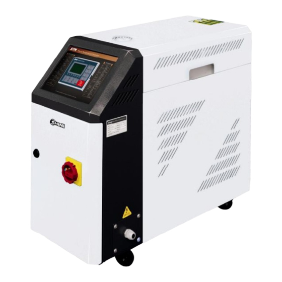
- Page 1 STM-PW series Hi-Temp. Water Heaters Date : June. 2009 Version : V2.3 (English)
- Page 3 Contents Contents ------------------------------------------------------ Technical Specifications ------------------------------------------------- --------------------------------------------------- General Description -------------------------------------------------------------- Working Principle ------------------------------------------------------------------ Safety Regulations -------------------------------------------------------- Signs and Labels ------------------------------------------------------------------ Operation Regulations ------------------------------------------------------------ Installation ------------------------------------------------------------------ Installation Space ------------------------------------------------------------------- Mould and Water Couplings ----------------------------------------------------- Power Supply ----------------------------------------------------------------------- Operation Guide ---------------------------------------------------------- Check Before Starting ------------------------------------------------------------- Start the Machine ------------------------------------------------------------------ Stop the Machine ------------------------------------------------------------------ Temperature Controller ------------------------------------------------------------...
- Page 4 Contents 7.5 The Useful Life of The Key Parts of The Product...
-
Page 5: General Description
1. General Description 1. General Description Please read through this operation manual before using and installation to avoid damage of the machine and personal injuries. STM- PW series high temperature water heaters are used to heat up the mould and maintain temperature, although they can be used in other similar applications. - Page 6 Other chapters contain instructions for the daily operator. Any modi cations of the machine must be approved by SHINI in order to avoid personal injury and damage to machine. We shall not be liable for any damage caused by unauthorized change of the machine.
-
Page 7: Technical Specifications
2. Technical Specifications 2. Technical Specifications 2.1 STM-607- PW 2.1.1 Specificatio ns Pum Performance curve pressure (Bar) Pipe heater: 6 kW Pump power: 0.55/0.63 kW Max. pump flow: 27 L/min Max. pump pressure: 3.8 Bar Cooling method: direct Mould coupling (Optional) : 3/8 "(2 2) - Page 8 2. Technical Specifications STM-910- PW Pum Performance curve pressure (Bar) (Optional) Flow rate (L/min) Outer demension s...
-
Page 9: Specifications
2. Technical Specifications STM-1220 -PW Specificatio ns Pum Performance curve pressure (Bar) (Optional) Flow rate (L/min) Outer demension s... -
Page 10: Specificati On List
2. Technical Specifications Specificati on List Max. pump Max. pump Mould Heater Pump (kw) Weight Heating / cooling Dimensions (mm) Heating chamber Cooling flow (L/min) pressure (bar) model Max. temp. coupling* (kw) (50/60Hz) (kg) tank (L) (H W D) number method (50/60Hz) (50/60Hz) - Page 11 3. Main Functions General Description SHINI Hi-temp. Water Heaters are mainly used to heat up the mould and keep its temp. at a certain level, and they are also found applications in other similar fields. Water returned from the mould will be cooled by...
- Page 12 3. Main Functions High-temperature water returning from mould returns to cooler through pipes, which is conveyed to heater after being pressured through pumping and it is transmitted to mould after being heated in electric thermal pipe, so on and so forth.
-
Page 13: Safety Regulations
4. Safety Regulations 4. Safety Regulations Danger! The unit is designed endure high temp. And high pressure. For safe operation, do not remove the covers or switches. Attention! The unit should be operated by qualified personnel only. During operation, avoid wearing gloves or clothes that may cause danger. -
Page 14: Signs And Labels
4. Safety Regulations 4.1 Signs and Labels In order to keep a stable temperature, cooling water pressure should not be less than 2kg/cm , but also no more than 5kg/cm . Clean the Y type strainer to ensure cooling capacity of the machine. -
Page 15: Operation Regulations
4. Safety Regulations Please abide by the safety guide when you operate the machine so as to prevent damage of the machine and personal injuries. All electrical components should be installed by qualified electricians. Turn off main switch and control switch during repair and maintenance. Warning High voltage This mark is attached on the cover of the control box. - Page 16 Transportation and storage of the machine Transportation 1) STM-PW series standard oil heaters are packed in crates or plywood cases with wooden pallet at the bottom, suitable for quick positioning by fork lift. 2) After unpacked, castors equipped on the machine can be used for ease of movement.
-
Page 17: Fire Hazard
4. Safety Regulations 4) This equipment works normally in the environment with altitude within 3000m. 5) At least a clearance of 1m surrounding the equipment is required during operation. Keep this equipment away from flammable sources at least two meters. 6) Avoid vibration, magnetic disturbance at the operation area. -
Page 18: Installation Space
5. Installation 5.1 Installation Space During installation of the machine, keep at least 500mm installation space around the machine as shown by the picture. Do not install the machine in a position crowded with other objects. This would cause inconvenience to operation, maintenance and repair. - Page 19 5. Installation 5.2 Mould and Water Couplings 1) It is necessary, while connecting from the access to mould, to use two spanners to fix the switching connection and ball valve before screw tightly the horn nut of the connection pipe, otherwise water might leaks from the machine.
-
Page 20: Power Supply
5. Installation 5.3 Power Supply Make sure that power supply is the same as required before installation. Mould heaters are generally set to be used with 3 400V power supply or other specifications according to customers' requirement. -
Page 21: Control Panel
6. Operation Guide 6. Operation Guide 6.1 Control Panel Name Functions Remarks Power supply Connect the machine with power supply Note! Do not remove any electrical indicator and turn on main switch. This indicator parts or terminals after the power is on. turns green. - Page 22 6. Operation Guide Name Functions Remarks Motor overload When motor current exceeds the limits, Check that if motor shaft is blocked or alarm the buzzer sounds. Motor overload the bearing is broken or setting current alarm is red and system stops working. of overload relay is too low.
-
Page 23: Machine Startup
6. Operation Guide 6.2 Machine Startup 1) Pipe connect the inlet and outlet of the standard water heater to the pipe of mould (refer to chapter 5.2 for details). 2) Connect the cooling water inlet /backup water inlet (refer chapter 5.5.2 for details). 3) Turn all the ball valves on. -
Page 24: Stop The Machine
6. Operation Guide 6.3 Stop the Machine 1) Switch off heater power. 2) Wait until oil temperature falls below 50 , turn off pump switch. 3) Turn off main switch. Warning! When main switch is turned on, be careful of electrical shock. Note! Pump motor rotating direction should be the same as indicated. - Page 25 6. Operation Guide 6.4.1 Temperature controller display Practical value: display practical temperaure value or parameter code of temperature controller. Setting value: display set temperature value or parameter value, or display input value when you set parameters. Operation indicator ALM1 (alarm 1) This indicator becomes bright to indicate that heater 2 has stopped working.
- Page 26 6. Operation Guide 6.4.2 Keys on control panel (Menu) press this key to show the items you want to reset. (mode) press this key to choose a parameter. (increase value) press this key to increase setting value. (decrease value) press this key to decrease setting value. 6.4.3 Choose a parameter Press to choose a parameter or switch to next parameter.
- Page 27 6. Operation Guide Confirm your setting when changing to another menu. 4) Before power supply is cut off, press to confirm your setting. Attention! Before delivery, the parameters of temp. controller are set already. Do not reset the parameters unless it is necessary.
-
Page 28: Service And Maintenance
7. Service and Maintenance 7. Service and Maintenance Pay attention to the following rules during maintenance: 1) Please reduce the temperature to room temperature (below50 ), cut off power supply and drain oil and water first while inspecting the machine; carry out operations with safety gloves on after complete confirmation of spaces for inspection and maintenance. - Page 29 7. Service and Maintenance 3) Open the cover of control box. Screw off two butterfly screws to unlock the cover. (Refer to the pictures below) Butterfly screws 7.2 Y Type Strainer 1) Clean soft water should be used as cooling water. Filter screen is used in the strainer to stop impurities and pollutants to enter into water pipe.
- Page 30 7. Service and Maintenance 7.4 Pipe Heater 1) Open machine rear cover door. (Refer to pictures below) 2) Unlock heater cap. (Refer to pictures below) 3) Unlock the screws of pipe heater to take it out. (Refer to the pictures below.) 4) Install the pipe heater in a reverse order.
- Page 31 7. Service and Maintenance The Useful Life of The Key Parts of The Product...
-
Page 32: Troubleshooting
8. Trouble Shooting 8. Trouble Shooting Failures Possible reasons Solutions Main power indicator Did not connect through power Connect through power supply. does not become bright supply. Replace main switch. after main switch is Main switch broken. turned on. Check electrical wires. ¡£... - Page 33 8. Trouble Shooting Failures Possible reasons Solutions Main switch indicator PCB output relay problems. won't become bright Check or replace the PCB. Pump switch problems. after turning on main Replace the switch. Time relay (K5) problems. switch. Pump can not Replace time relay.
-
Page 34: Assembly Drawing And Parts List
9. Assembly Drawing and Parts List 9. Assembly Drawing and Parts List... - Page 35 9. Assembly Drawing and Parts List -607-P...
- Page 36 9. Assembly Drawing and Parts List Main power supply switch* Door plate Long door plate Electric-controlled ground plate Electric control box Temperature controller Operation panel Alternation switch Circuit board buzzer Side plate Back plate of electric control box M8X20 Inner hexagon screw Beam Clapboard Inlet pressure switch *...
- Page 37 9. Assembly Drawing and Parts List Safety release valve Cooled water electromagnetic valve* PT 1 PT Stainless steel elbow Copper connection H Teflon pipe connection PT 1 H Teflon pipe connection Filtering valve* Core Electric heat tube unit* M10x25 Inner hexagon screw Electric heat tube shield Release electromagnetic valve Thermocouple *...
- Page 38 9. Assembly Drawing and Parts List Cooling bucket Ground plate EGO* EGO mounting panel Rib reinforcement Plastic core-rubber-tires Fan* PT 3 H copper connection with external teeth at the two ends (L type) *Indicates latent wearing parts **Indicates latent wearing parts and it's suggested to back them up.
- Page 39 9. Assembly Drawing and Parts List -910-P...
- Page 40 9. Assembly Drawing and Parts List Main power supply switch* Door plate Long door plate Electric-controlled ground plate Electric control box Temperature controller Operation panel Alternation switch Circuit board buzzer Side plate Back plate of electric control box M8X20 Inner hexagon screw Beam Clapboard Inlet pressure switch *...
- Page 41 9. Assembly Drawing and Parts List Safety release valve Cooled water electromagnetic valve PT 1 PT Stainless steel elbow Copper connection H Teflon pipe connection PT 1 H Teflon pipe connection Filtering valve Core Electric heat tube unit* M10x25 Inner hexagon screw Electric heat tube shield Release electromagnetic valve Thermocouple *...
- Page 42 9. Assembly Drawing and Parts List Cooling bucket Ground plate EGO* EGO mounting panel Rib reinforcement Plastic core-rubber-tires Fan* PT 3 H copper connection with external teeth at the two ends (L type) *Indicates latent wearing parts **Indicates latent wearing parts and it's suggested to back them up.
- Page 43 9. Assembly Drawing and Parts List -1220-P 9-10...
- Page 44 9. Assembly Drawing and Parts List Main power supply switch* Door plate Long door plate Electric-controlled ground plate Electric control box Temperature controller Operation panel Alternation switch Circuit board buzzer Side plate Back plate of electric control box M8X20 Inner hexagon screw Beam Clapboard Inlet pressure switch *...
- Page 45 9. Assembly Drawing and Parts List Safety release valve Cooled water electromagnetic valve* PT 1 PT Stainless steel elbow Copper connection H Teflon pipe connection PT 1 H Teflon pipe connection Filtering valve* Core Electric heat tube unit* M10x25 Inner hexagon screw Electric heat tube shield Release electromagnetic valve Thermocouple*...
- Page 46 9. Assembly Drawing and Parts List Cooling bucket Ground plate EGO* EGO mounting panel Rib reinforcement Plastic core-rubber-tires Fan* PT 3 H copper connection with external teeth at the two ends (L type) *Indicates latent wearing parts **Indicates latent wearing parts and it's suggested to back them up. 9-13...
- Page 47 9. Assembly Drawing and Parts List 1. Pump body 2. Sleeve 3. O shape ring 4. Key 5. Pump cover 6. Socket cap screw 7. Neck ring 8. Mechanical seal 9. Rotary ring 10. Motor 9-14...
-
Page 48: Electrical Circuit
10. Electrical Circuit 10. Electrical Circuit 10.1 STM-607-PW 10.1.1 Main electrical circuit 10-1... -
Page 49: Electrical Components Layout
10. Electrical Circuit 10.1.2 Electrical components layout PC(AA-01) 10-2... - Page 50 10. Electrical Circuit Connect power supply ground wire Connect heater ground wire Connect pump ground wire Connect with control board ground wire Connect door plate ground wire 10-3...
- Page 51 10. Electrical Circuit 10.1.4 Electrical components layout 10-4...
- Page 52 10. Electrical Circuit Symbol Specifications Name Part No. Main switch E1416000 Circuit_breakers* E3121030 Excitation Break Away E3121010 Contactors* 230V 50/60Hz E1130100 Auxiliary contact terminal E1140102 Auxiliary contact terminal E1140012 Contactors* 230V 50/60Hz E1131000 Overload Relays* 1.6~2.5A E1216250 Transformer IN=400V OUT=230V 500mA E3305000 Fuse box* 32A 2P...
- Page 53 10. Electrical Circuit Symbol Specifications Name Part No. Main switch E1425000 Circuit_breakers* E3121060 Excitation Break Away E3121010 Contactors* 230V 50/60Hz E1130100 Auxiliary contact terminal E1140102 Auxiliary contact terminal E1140012 Contactors* 230V 50/60Hz E1131000 Overload Relays* 2~3.2A E1202320 Transformer IN=400V OUT=230V 500mA E3305000 Fuse box* 32A 2P...
- Page 54 10. Electrical Circuit Symbol Specifications Name Part No. 400V 50Hz Heater** Fan* 230V 50/60Hz *Indicates latent wearing parts **Indicates latent wearing parts and it's suggested to back them up. 10-7...
- Page 55 10. Electrical Circuit Symbol Specifications Name Part No. Main switch E1432000 Circuit_breakers* E3114004 Excitation Break Away E3121010 Contactors* 230V 50/60Hz E1130100 Auxiliary contact terminal E1140102 Auxiliary contact terminal E1140012 Contactors* 230V 50/60Hz E1131000 Overload Relays* 4~6.3A E1204631 Transformer IN=400V OUT=230V 500mA E3305000 Fuse box* 32A 2P...
- Page 56 10. Electrical Circuit Symbol Specifications Name Part No. 400V 50Hz 1.5kW Motor Heater** 400V 50Hz Fan* 230V 50/60Hz *Indicates latent wearing parts **Indicates latent wearing parts and it's suggested to back them up. 10-9...
-
Page 57: Overload Relay
10. Electrical Circuit 10.3 Main Electrical Components List Overload relay 1) Terminal for contact coil A2. 2) Setting current adjusting scale. 3) Reset (blue). H: manual reset A: automatic reset 4) Stop. 5) ON / OFF idication and TEST function. 6) Auxiliary contact terminals shown in 95.96.97.98. -
Page 58: Maintenance Schedule
11. Maintenance Schedule 11. Maintenance Schedule 11.1 About the Machine Model: Manufacturing date: Voltage: Frequency: Total power: 11.2 Check after Installation Check the installation space is enough as required. Check the pipes are correctly connected. Electrical installation Voltage: Fuse melting current: 1 Phase 3 Phase Check phase sequence of power supply. -
Page 59: Daily Checking
11. Maintenance Schedule 11.3 Daily Checking Check machine startup function Check machine startup function Check machine startup function Check all the electrical wires Check all the electrical wires Check all the electrical wires Check machine startup function Check machine startup function Check machine startup function Check all the electrical wires Check all the electrical wires... - Page 60 11. Maintenance Schedule Check machine startup function Check machine startup function Check machine startup function Check all the electrical wires Check all the electrical wires Check all the electrical wires Check machine startup function Check machine startup function Check machine startup function Check all the electrical wires Check all the electrical wires Check all the electrical wires...
- Page 61 11. Maintenance Schedule Check machine startup function Check machine startup function Check machine startup function Check all the electrical wires Check all the electrical wires Check all the electrical wires Check machine startup function Check machine startup function Check machine startup function Check all the electrical wires Check all the electrical wires Check all the electrical wires...
-
Page 62: Weekly Checking
11. Maintenance Schedule 11.4 Weekly Checking Check machine startup function Check machine startup function Check machine startup function Check all the electrical wires Check all the electrical wires Check all the electrical wires Check loose electrical connections Check loose electrical connections Check loose electrical connections Check and clean Y type strainer Check and clean Y type strainer... - Page 63 11. Maintenance Schedule Check machine startup function Check machine startup function Check machine startup function Check all the electrical wires Check all the electrical wires Check all the electrical wires Check loose electrical connections Check loose electrical connections Check loose electrical connections Check and clean Y type strainer Check and clean Y type strainer Check and clean Y type strainer...
- Page 64 11. Maintenance Schedule Check machine startup function Check machine startup function Check machine startup function Check all the electrical wires Check all the electrical wires Check all the electrical wires Check loose electrical connections Check loose electrical connections Check loose electrical connections Check and clean Y type strainer Check and clean Y type strainer Check and clean Y type strainer...
-
Page 65: Monthly Checking
11. Maintenance Schedule 11.5 Monthly Checking Check loose electrical connections Check loose electrical connections Check loose electrical connections Check and clean Y type strainer Check and clean Y type strainer Check and clean Y type strainer Clean solenoid valve Clean solenoid valve Clean solenoid valve Check loose electrical connections Check loose electrical connections... - Page 66 11. Maintenance Schedule Check loose electrical connections Check loose electrical connections Check loose electrical connections Check and clean Y type strainer Check and clean Y type strainer Check and clean Y type strainer Clean solenoid valve Clean solenoid valve Clean solenoid valve Check loose electrical connections Check loose electrical connections Check loose electrical connections...
-
Page 67: Half-Yearly Checking
11. Maintenance Schedule 11.6 Half-yearly Checking Check damaged pipes Check damaged pipes Check damaged pipes Check and clean Y type strainer Check and clean Y type strainer Check and clean Y type strainer Clean solenoid valve Clean solenoid valve Clean solenoid valve Check damaged pipes Check damaged pipes Check damaged pipes... - Page 68 (d) Wear parts and accessories. 7. If your SHINI product is not the same place of purchase, you can still send the product to your local SHINI's branch or distributor for servicing at your full costs according to the individual country service policy.
- Page 69 Date of purchase: Please send all queries and comments to: Shini Plastics Technologies, Inc. Corporate Product & Marketing Center 1 Shini Road, Dalang, Dongguan, Guangdong, China Tel: (0769) 8331 3588 Fax: (0769) 8331 3589 Corporate e-mail: shini@shini.com Corporate internet: www.shini.com...
Need help?
Do you have a question about the STM-PW series and is the answer not in the manual?
Questions and answers