Advertisement
Quick Links
Advertisement

Related Manuals for Shini STM-PW


Summary of Contents for Shini STM-PW
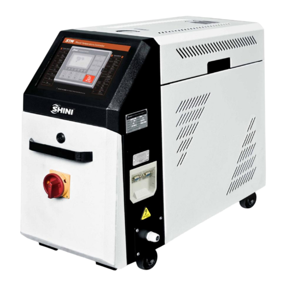
- Page 1 STM-PW High Temp. Water Heater Date:Jan. 2019 Version: Ver.H (English)
- Page 3 Contents General Description ..................7 1.1 Coding Principle ..................8 1.2 Feature ....................8 1.3 Options ....................8 1.4 Technical Specifications ................ 10 1.4.1 Specification ................10 1.4.2 Reference Formula of Mould Controllers Model Selection ..11 1.5 Safety Regulations ................11 1.5.1 Safety Signs and Labels .............
- Page 4 4.4.2 Output Setting ................29 4.4.3 Alarm Settings ................30 4.4.4 Instrument Setting............... 31 4.4.5 SUCTION Function ..............31 4.4.6 Water Replenishment Function ..........31 4.4.7 Exhaust valve function ..............32 4.4.8 Plunger pump function ..............33 4.5 Errors and Causes ................34 Trouble-shooting ..................
- Page 5 Table 4-6: Temp. Setting .................. 27 Table 4-7: Time Setting ..................27 Table 4-8: One Week ON/OFF Setup ............... 27 Table 4-9: Communication Setup ..............28 Table 4-10: Instrument Setup ................28 Table 4-11: Refilling Setup ................28 Picture Index Picture 2-2: Working Principle ................
- Page 6 6(42)
- Page 7 Read this manual carefully before operation to prevent damage of the machine or personal injuries. STM-PW series high temp. water heaters are used to heat up the mould and maintain temperature, they can be used in other similar applications as well. High temp.water from mould through high-temp.
- Page 8 1.1 Coding Principle 1.2 Feature l P.I.D. multi-stage temperature control system can maintain an mould temperature with accuracy of ±0.5℃. l Adopts high efficiency water cycle magnetic pump, with which precise moulds and mould loop with minor diameter can achieve precise temperature control and high efficient heat exchange.
- Page 9 Chapter 6, which contains service instructions intended for service engineers. Other chapters contain instructions for the daily operator. Any modifications of the machine must be approved by SHINI in order to avoid personal injury and damage to machine. We shall not be liable for any damage caused by unauthorized change of the machine.
- Page 10 1.4 Technical Specifications 1.4.1 Specification Table 1-1: Specification Model STM-607PW STM-607PW-D STM-1220PW STM-1220PW-D STM-2440PW Ver. Max. temp 180℃ Heater (kW) 6×2 12×2 Pump (kw) (50/60Hz) 0.6×2 1.05 1.05×2 Max. pump flow 25.5/28 25.5/28 50/60 50/60 100/120 (L/min) (50/60Hz) Max. pump pressure 4.8/6.3 4.8/6.3 5.8/7.6...
- Page 11 1.4.2 Reference Formula of Mould Controllers Model Selection Heater Power (kW) = mould weight (kg) × mould specific heat (kcal/kg℃) × temperature difference between mould and environment (℃) × safety coefficient / heating duration / 860 Note: safety coefficient can select a value from 1.3 to 1.5. Flow Rate (L/min) = heater power (kw) ×...
- Page 12 Do not use the machine before fully aware of its performance. Be careful not to touch or hit the switch or sensor. Please keep enough operation space, and keep away obstacles. To avoid producing statics, clean the floor from oil or water to keep a dry environment.
- Page 13 Water outlet: drainage outlet. Water inlet: inlet for replenishing water and cooling water. Please abide by the safety guide when you operate the machine so as to prevent damage of the machine and personal injuries. All electrical components should be installed by qualified electricians. Turn off main switch and control switch during repair and maintenance.
- Page 14 100℃. 1.5.4 Transportation and Storage of the Machine Transportation 1) STM-PW series standard oil heaters are packed in crates or plywood cases with wooden pallet at the bottom, suitable for quick positioning by fork lift.
- Page 15 1) Indoors in a dry environment with maximum temperature +45℃ and humidity not more than 80%. Do not use the machine: 1) If it is with a damaged cord. 2) On a wet floor or when it is exposed to rain to avoid electrical shock. 3) If it has been dropped or damaged until it is checked or fixed by a qualified serviceman.
- Page 16 Shini (including employees and agents). Shini is exempted from liability for any costs, fees, claims and losses caused by reasons below: 1. Any careless or man-made installations, operation and maintenances upon machines without referring to the Manual prior to machine using.
- Page 17 Structure Characteristics and Working Principle 2.1 Working Principle Picture 2-1: Working Principle High-temp. water from the mold turns back to pump inlet through the pipeline and is sent to the heater by pump pressurizing, then it gets into the mold after heating by pipe heater, and so on.
- Page 18 2.2 Options Installation 2.2.1 Installation steps for options water manifold (dewaxing) 1) Install copper joint to the level valve. 2) Install level valve with copper joint to the dewaxing water manifold. 3) Install water manifold to the machine. 4) Install Teflon to copper joint. Note: For the operating temperature not higher than 200 ℃...
- Page 19 2.2.2 Installation steps for options water manifold (welding) 1) Install copper joint to the level valve. 2) Install level valve with copper joint to the welding water manifold. 3) Install water manifold to the machine. 4) Connect water manifold with manifold joint via screws. 5) Install Teflon to copper joint.
- Page 20 3. Installation and Debugging 3.1 Installation Space During installation of the machine, keep at least 500mm installation space around the machine as shown by the picture. Do not install the machine in a position crowded with other objects. This would cause inconvenience to operation, maintenance and repair.
- Page 21 2) Unused mould couplings can be connected with each other by a teflon pipe, as shown in. Picture 3-3: Mould and Water Couplings 2 3) Connect cooling water inlet with water supply and cooling water outlet with a drainage pipe. After that, turn on water supply. Picture 3-4: Mould and Water Couplings 3 Note: Cooling water inlet and outlet as shown by the Figure.
- Page 22 Operation Guide 4.1 Control Panel Picture 4-1: Control Panel Table 4-1: Key Function Specification Name Functions Remarks Heating(Main) Heating output indicator Heating(SUB) Auxiliary heating output indicator Cooling Cooling indicator Display pump positive Pump rotating action indicator Pump rotating Pump reverse action indicator direction reverse Water supply Water refilling indicator...
- Page 23 Name Functions Remarks Auto-tuning Auto tuning key Reverse/Drain Reverse running/discharge Hold the button for 2 secs to enable force cooling. It stop heating while enable Mandatory cooling Forced cooling key 100% cooling. It stops after the temperutre drops below Cooling Temp. After press”...
- Page 24 4.2 Menu Introduction Power on ON/OFF Shini welcome screen Main screen MENU Password Input MENU Screen MENU Control setup Alarm setup Output setup Temp. setup 1:Phase detect. 1:U L temp. 1: Aux. output 2:Ret. water temp. dev.. 2:L L temp.
- Page 25 4.3 Menu Introduction 4.3.1 Main screen 30℃ Current temp. 70℃ Current target Display 3 Display 1 Display 2 Display 4 Picture 4-2: Main Menu Screen Display Function Display 1 Display system time Display 2 Reserved time (reserve startup) / output percentage (start temp.control) Display 3 System state / return water temp.(Return water and mould temp.
- Page 26 2. In the function menu, select different parameters by pressing <up> or <down> button. 4.4 Parameter Table 4.4.1 Parameter Setting Table Table 4-2: Main Screen Parameter Description Range Default Control temp. 0-350 (32 180℃ ℃ ℉-662℉) Table 4-3: Control Setting Parameter Description Range...
- Page 27 Table 4-5: Output Setting Parameter Description Range Default Auxiliary output Auxiliary output OFF temp. 0-300 (0= not use) 1℃ ℃ Cooling temp. Forced cooling temp. 0-100 (0= not use) 35℃ ℃ machine running time before Overhaul temp. 0-10000H(0= not use) maintenance Total running time Total machine running time Table 4-6: Temp.
- Page 28 Table 4-9: Communication Setup Parameter Description Range Default Comm. protocol Comm. protocol Modbus-RTU Modbus-RTU Comm. unit No. Comm. address 1-99 Comm. speed Comm. speed 4800、9600、19200 19200 Comm. length Data length 7, 8Bit 8Bit Stop bit stop bit 1, 2Bit 1Bit Check bit check bit -,odd,even...
- Page 29 4.4.2 Output Setting 1. Main output and auxiliary output of heating control 1) When control temp. is smaller than set value, initiate main output and auxiliary output to promptly improve the temp. 2) Alternatively select the main output and auxiliary output. SV=100℃...
- Page 30 4.4.3 Alarm Settings 1. Phase shortage and reverse alarm 1) The alarm will sound when the phase can’t be detected or R, S, T wrong connection, and the control will stop. 2. Water output temp. deviation and mould temp. deviation alarm 2) If the difference of control temp.
- Page 31 SV=100℃ Start control Control temp. 95℃(SV-5℃) Alarm dismissed Heat alarm It doesn’t reach sv-5℃ in heating alarm set time time, the alarm will sound. 4.4.4 Instrument Setting Parameters Meaning Language selection English/Chinese The external voltage (1-5VDC) signal can be used to set the control temp.
- Page 32 2) Low level contact input signal, and the replenishment relay immediately starts the refilling. 2. Startup replenishment 1) When the startup time is set as 601s, the water level will be replenished to the high level, it then starts PID operation. 2) When the startup replenishment <601S, the PID will operate after water replenishment processed according to the set time.
- Page 33 2. When machine enters the running state, after the actual temperature rises to a constant value (can be set), the exhaust valve will open for some time (can be set) to be used for the limitation system pressure and ensure normal operation.
- Page 34 Errors and Causes Temp. Errors Causes Alarm control Phase alarm phase shortage or phase reverse detected occur stop EGO contact input detected occur stop Pump overload pump overload contact input detected occur stop High pressure input high pressure contact input occur stop Low pressure input...
- Page 35 Trouble-shooting Failures Possible reasons Solutions Did not connect through power Connect through power supply. LCD displays nothing supply. Replace main switch. after switch on power Main switch broken. Check electrical wires. and press ON/OFF Power supply wires problems. Fix the fuse. key.
- Page 36 Failures Possible reasons Solutions Short circuit of main circuit. Circuit breaker tripping Transformer short circuit or Check electrical wire. off at turning on main connected with earth wire. Replace circuit breaker. switch. Problems of circuit breaker. Circuit breaker tripping Pump motor coil short circuit. Check pump motor.
- Page 37 Maintenance and Repair Pay attention to the following rules during maintenance: 1) It requires two personnel to check the machine. Firstly, reduce the temperature, cut off the power supply, and drain the oil and water; Make sure to operate after inspection with enough maintenance space. 2) When operating, it’s dangerous to touch the machine as it is in high temperature state.
- Page 38 6.1 Open the Covers 1) Open the top covers of the unit (Lift up it as shown picture). Picture 6-1: Open the Covers 1 2) Take down the side covers (Pull up it outward as shown picture). Picture 6-2: Open the Covers 2 3) Open the cover of control box.
- Page 39 6.2 Y Type Strainer 1) Clean soft water should be used as cooling water. Filter screen is used in the strainer to stop impurities and pollutants to enter into water pipe. 2) Impurities or pollutants may cause errors and bad temperature control. Clean filter screen of the strainer periodically.
- Page 40 6.4 Pipe Heater 1) Open machine rear cover door. (Refer to pictures below) Picture 6-6: Pipe Heater 1 2) Unlock heater cap. (Refer to pictures below) Picture 6-7: Pipe Heater 2 3) Unlock the screws of pipe heater to take it out. (Refer to the pictures below.) Picture 6-8: Pipe Heater 3 4) Install the pipe heater in a reverse order.
- Page 41 6.5 Maintenance Schedule 6.5.1 About the Machine Model Manufacture date Voltage Ф Frequency Power 6.5.2 Installation & Inspection Check the installation space is enough as required. Check the pipes are correctly connected. Electrical installation Voltage: Fuse melting current: 1 Phase 3 Phase Check phase sequence of power supply.
- Page 42 Replace the hot kerosene with a using temperature above 120~160 degree 6.5.7 Yearly Checking Replace the hot kerosene with a using temperature above 120 degree 6.5.8 3 year Checking PC board renewal. No fuse breaker renewal. Note: 1. Y-type filter has the function of filling water cooling protection effect, be sure the waterway are clear to avoid cooling failure.
Need help?
Do you have a question about the STM-PW and is the answer not in the manual?
Questions and answers