Table of Contents
Advertisement
Quick Links
Advertisement
Table of Contents

Related Manuals for Shini STM-W


Summary of Contents for Shini STM-W
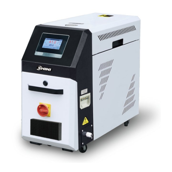
- Page 1 STM-W Water Heater Date: Jan. 2024 Version: Ver.H (English)
-
Page 2: Table Of Contents
Contents General Description ..................6 1.1 Coding Principle ..................7 1.2 Feature ....................7 1.3 Options ....................8 1.4 Reference Formula of Mould Controllers Model Selection ...... 9 1.5 Safety Regulations .................. 9 1.5.1 Safety Signs and Labels ............... 9 1.5.2 Signs and Labels ................ - Page 3 4.4.1 User Parameter Settings ............24 4.4.2 Action Setting ................25 4.4.3 Clock Timing ................26 4.4.4 System Setting ................27 4.4.5 Data Download ................28 4.4.6 Advanced Setting ............... 29 4.4.7 Factory Setting ................34 4.5 Current Fault Inquiry ................43 4.6 Inquiry Screen ..................
- Page 4 Table 4-4:Project Parameter Description ............30 Table 4-5:Default Parameters and Meanings ..........36 Table 4-6:Controller Exception List ..............38 Table 4-7: Current Fault Inquiry Screen Icon Key Description ......43 Picture Index Picture 1-1: Water Heater STM-607W ..............6 Picture 2-1: Working Principle ................14 Picture 3-1: Installation Space ................
- Page 5 Picture 4-24: Current Fault Screen ..............43 Picture 4-25: History Fault Inquiry Screen ............44 Picture 4-26: User Setting Screen ..............44 Picture 4-27: Data Inquiry Screen ..............45 Picture 4-28: Output Inquiry Screen ..............45 Picture 4-29: Input Inquiry Screen ..............45 Picture 4-30: Version Inquiry Screen ..............
-
Page 6: General Description
Read this manual carefully before operation to prevent damage of the machine or personal injuries. The STM-W series of standard water heaters are used to heat up the mould and maintain this temperature. Besides, they can also be used in other similar applications. -
Page 7: Coding Principle
8) For standard STM-W, the heating temperature can reach 120℃. 9) Equipped with high pressure protection, safety pressure relieving, automatic water supplying and air exhausting. -
Page 8: Options
Chapter 6, which contains service instructions intended for service engineers. Other chapters contain instructions for the daily operator. Any modifications of the machine must be approved by SHINI in order to avoid personal injury and damage to machine. We shall not be liable for any damage caused by unauthorized change of the machine. -
Page 9: Reference Formula Of Mould Controllers Model Selection
Reference Formula of Mould Controllers Model Selection Heater Power (kW) = mould weight (kg) × mould specific heat (kcal/kg℃) × temperature difference between mould and environment (℃) × safety coefficient / heating duration / 860 Note: safety coefficient can select a value from 1.3 to 1.5. Flow Rate (L/min) = heater power (kw) ×... -
Page 10: Signs And Labels
Do not touch the switch with wet object or hands. Do not use the machine before fully aware of its performance. Be careful not to touch or hit the switch or sensor. Please keep enough operation space, and keep away obstacles. To avoid producing statics, clean the floor from oil or water to keep a dry environment. -
Page 11: Operation Regulations
From mould: connector for circulating water/oil coming from mould. To mold: connector for circulating water/ oil to go to mould. 1. To maintain temperature consistency, cooling water pressure must be higher than 2 bar at all time, but should never exceed 5 bar in any case. 2. - Page 12 5) The mould temperature controller has pump overloader: When it is over loaded, the pump and pipe heater will stop. At this time, check the reasons of pump overload (phase shortage, pipe blockage, bearing damage etc.). After all is normal, reset the overload protector (RESET) or wait for the pump temp.
-
Page 13: Exemption Clause
The following statements clarify the responsibilities and regulations born by any buyer or user who purchases products and accessories from Shini (including employees and agents). Shini is exempted from liability for any costs, fees, claims and losses caused by reasons below: 1) Any careless or man-made installations, operation and maintenances upon machines without referring to the Manual prior to machine using. -
Page 14: Structure Characteristics And Working Principle
Structure Characteristics and Working Principle 2.1 Main Functions The STM-W series of standard water heater are used to heat up the mould and maintain this temperature. Besides, they can also be used in other similar applications. High temperature water from the mould is cooled by direct cooling and then sent to the pipe heater via high-pressure pump for heating to a constant temperature. -
Page 15: Installation And Debugging
Installation and Debugging 3.1 Installation Space During installation of the machine, keep at least 500mm installation space around the machine as shown by the picture. Do not install the machine in a position crowded with other objects. This would cause inconvenience to operation, maintenance and repair. -
Page 16: Power Supply
Cooling Cooling water inlet water outlet Picture 3-2:Pipe Connection Table 3-1:Cooling Water Inlet and Outlet Specification Model Cooling Water Inlet Cooling Water Outlet Connector Type Φ13mm Φ13mm STM-607W/910W Pagoda (ext. diameter) (ext. diameter) Φ13mm Φ13mm STM-1220W/2440W Pagoda (ext. diameter) (ext. diameter) Φ13mm Φ13mm STM-3650W... -
Page 17: Options Installation
5) The machine requires 3-phase 4-wire power source, connect the power lead (L1, L2, L3) to the live wires, and the earth (PE) to the ground. 6) Power supply requirements: Main power voltage: +/- 5% Main power frequency: +/- 2% 7) Please refer to electrical drawing of each model to get the detailed power supply specifications 3.4 Options Installation... -
Page 18: Installation Steps For Options Water Manifold (Welding)
3.4.2 Installation steps for options water manifold (welding) 1) Install copper joint to the level valve. 2) Install level valve with copper joint to the welding water manifold. 3) Install water manifold to the machine. 4) Connect water manifold with manifold joint via screws. 5) Install Teflon to copper joint. -
Page 19: Installation Steps For Function Of Water Drainage Via. Air Blowing
3.4.3 Installation Steps for Function of Water Drainage via. Air Blowing 1) Connect the air blowing joint parts to “Toward mold mouth” on mold temperature controller and then istall the water distributor. 2) In shutdown, click the menu button on the main page, enter the user settings screen, and click on the operation buttons. -
Page 20: Installation And Operation Steps Of The Optional Manual Air Drainer
3.4.4 Installation and Operation Steps of the Optional Manual Air Drainer 1) Connect the assemblies of the manual air drainer connector to the mould, and then install the water flow regulator. 2) Open the ball valve on the manual air drainer connector when the machine is shutdown to blow and drain the water. -
Page 21: Operation Guide
Operation Guide Machine Startup After the system is powered on, the panel displays the startup screen, as below: Picture 4-1:Startup Screen Main Screen 4.2.1 Standby Screen Picture 4-2:Standby Screen 21(62) - Page 22 Table 4-1:Standby Screen Specifications Function Name Description Type Setting Enter the user setting screen Forced button Start the forced cooling function Stop the forced cooling function cooling only Display the set temp. unit. The unit supports ℃/ Temp. unit shifting. display When the system fails, the main interface will flicker.
-
Page 23: Operation Screen
4.2.1 Operation Screen Pump forward/ reverse running Heating/cooling Low level Alarm Reverse emptying Inlet T Mold T Media P Media F Picture 4-3:Operation Screen Table 4-2:Operation Screen Specification Items Description Pump forward / the unit starts the pump forward / reverse running reverse running It starts the unit temp. -
Page 24: User Setting
2) When the temperature drops below 50 ℃ , press the<Forced cooling>button to turn off the forced cooling, and then press the<Run/Stop>button to stop the machine. 3) Turn the main power switch to OFF. Note: When the main power switch is ON, please be aware of the risk of electric shock! Attention: The pump direction must be correct! Attention: To reduce machine damage and extend its lifespan,... -
Page 25: Action Setting
Picture 4-6:User Parameter Screen Table 4-3:User Parameter Specification Initial Parameter Setting Range Unit Remarks Value When selecting the “use”, it’s not allowed to set Locking temp. disable disable- use temperature on the main interface. ℃ Setting temp. 80.0 0-120.0 Local: unit startup/shutdown can only be controlled locally. -
Page 26: Clock Timing
Picture 4-7:Action Setting Screen 4.4.2.1 Reverse Emptying After the machine stops, it will start pump reverse running and exhaust valve, which can be started and stopped manually or automatically (The factory default of reversal running time is 60S, and refer to the project parameter table for specific settings). -
Page 27: System Setting
picture below: Picture 4-9:Set Timing Switch Screen If the "Timing Main Switch" is set to "ON", press the < Clock > button in the "Operation" screen to enter the Timing Inquiry and Modification Screen. Clock Low level Inlet T Mold T Media P Media F Picture 4-10:Timer Inquiry and Modification Screen... -
Page 28: Data Download
Picture 4-11:System Setting Screen Set the backlight time: setting range is 0 ~ 255 secs. Language: Chinese or English The default user password is 123. See "Password Modification" for details; 4.4.5 Data Download When downloading data, please use the U disk format: FAT32, and the recommended U disk capacity is 16g or below. -
Page 29: Advanced Setting
"U disk" displays "connected" status, and then follow the prompts. Other operations are prohibited during the download process. Real-time data recording: After inserting the U disk and starting the real-time data recording function, then the temp. data will be updated in real time and stored in the U disk automatically, and the recording will be interrupted after unplugging the U disk. - Page 30 Picture 4-15:Project Screen In the "Project" screen, click the < Project Parameter > button to enter the project parameter setting Picture 4-16:Project Parameter Setting Screen Table 4-4:Project Parameter Description Control 12.0 1~30 Adjust PID control response response adjustment Ar ℃ Heating 0.1~200.0℃...
- Page 31 Control circuit: Control temp. probe only Control Control return medium: loop~control+return control temp. + return medium The number of control medium~control temp. probes circuit +mould~control+ Control + mould: control temp. return medium + mould temp. mould Control+mould+mould: control temp. + return medium temp. + mould temp.
- Page 32 temp. alarm medium output temp. |>【return medium temp. deviation 】 , delay 【 temp. deviation alarm delay 】secs., it alarms “Large return medium temp. ℉ 0-90.0 difference”, make auto reset. 0: disable (2) After modifying [SV] or forced cooling, this fault will not be solved in previous temp.
- Page 33 1. If the machine fails to reach the set temp. of - 5 ℃ within the [heater alarm] time, it will give the "heater alarm", and 分 Heater alarm 0~999 continue to control the temp. Manual reset. 2. Set to 0, disable the limit detection.
-
Page 34: Factory Setting
Comm. address SHINI SHINI, GBT Unit maintenance 0-3000 When the set accumulative time Maint running time is greater than Accumulative enan [unit maintenance time], it total running 0-3000 alarms” Unit Maintenance time (hr.) Fault”; Accumulative total running 0-59 Min. time (min.) 4.4.7 Factory Setting... - Page 35 User parameters, project parameters and manufacturer parameters can be initialized without initializing passwords. Picture 4-19: Parameter Initialization Screen 4.4.7.3 Fault Clearing Clear all historical faults. Picture 4-20: Fault Clearing Screen 4.4.7.4 Manufacturer Debugging User can enter this operation under non-operational status, and debug relay output.
- Page 36 Picture 4-21: Manufacturer Debugging Screen When the button is grey, press to start relay output. When the button is green, press to close the relay. 4.4.7.5 Default Parameter Table Table 4-5:Default Parameters and Meanings Initial Parameter Name Setting Range Unit Remarks Value common...
- Page 37 Manually adjust SW2 thin code switch AI2 input Current Current, voltage on the control board, specification and select the correct analog signal input. Upper limit of flow 200.0 0~999.9 L/min measurement Lower limit of flow 0~999.9 L/min measurement ℃ temp. upper 90.0 0~200.0...
- Page 38 High liquid level normal open normal open ~ normal close Table 4-6:Controller Exception List Fault Name Detection Logic Reset Mode 1. Power-on detection Pump overload Manual reset 2. Pump overload input point is valid, and the alarm delays 2 secs. Stop and release. 1.
- Page 39 2. AI 1 input is defined as "disabled", disable the fault. 1. Check whether the sensor input signal is normal. When it alarms, the machine runs continuously. Manual reset Flow sensor fault 2. AI2 input is defined as "disabled", disable the fault. 1.
- Page 40 Note: In order to prevent false alarm after modifying the set temp., the fault can only be solved after the PV temp. reaches the set temp. once. 1. When it alarms, the machine runs normally. 2. 【SV】-PV > 【Low temp. deviation alarm】, it delays 2 secs., and gives low temp.
- Page 41 (1)| Control temp. – mould temp. | > 【 Mould temp. deviation 】, it delays【 Temp. difference alarm delay 】 secs., and it alarms large return medium temp. difference. When the 【 Mould temp. deviation 】 = 0, disable this function.
- Page 42 Engineering Parameters - "Auxiliary". Built- in Modbus- Rtu protocol. Note: The communication address, Baud, check bit and stop bit are adjusted according to the actual demands. 2) Comm. address set selection: SHIINI(default):The address definition of Shini controller (as shown in the Appendix). 42(62)
-
Page 43: Current Fault Inquiry
Picture 4-23: Comm. Parameter Settings 4.5 Current Fault Inquiry When the unit fails, in the “Operation” screen, the < Fault Inquiry > button will flicker. At this time, click the < Fault Inquiry > button to silence and enter following screen: Picture 4-24: Current Fault Screen Table 4-7: Current Fault Inquiry Screen Icon Key Description... -
Page 44: History Fault Inquiry
4.6.1 History Fault Inquiry When there is no fault currently, click the < Fault Inquiry > button in the "Operation" screen to enter the history fault inquiry. Picture 4-25: History Fault Inquiry Screen 4.6.2 Inquiry Screen In the "Operation" screen, click the < Setting > button to enter the "User Setting" screen, and click the <... - Page 45 Picture 4-27: Data Inquiry Screen 4.6.2.2 Output Inquiry Picture 4-28: Output Inquiry Screen When the indicator is gray, it means that corresponding relay has no output. When the indicator light is green, it indicates that corresponding relay is outputting. 4.6.2.3 Input Inquiry Picture 4-29: Input Inquiry Screen When the indicator light is gray, it indicates that corresponding switch input is invalid.
- Page 46 When the indicator light is green, it indicates that corresponding switch input is valid. 4.6.2.4 Version Inquiry Picture 4-30: Version Inquiry Screen Take real display value as standard. 46(62)
-
Page 47: Trouble-Shooting
Trouble-shooting Failures Possible reasons Solutions Did not connect through power supply. Connect through power supply. LCD displays nothing Main switch broken. Replace main switch. after switch on power Power supply wires problems. Check electrical wires. and press ON/OFF key. Control circuit fuse melt. Fix the fuse. - Page 48 Heater contactor problems. Replace the contactor. Temperature can't rise Heater problems. Replace pipe heater. Thermocouple problems. Replace thermocouple. PCB output point problems. Check and repair PCB. Short circuit of main circuit. Circuit breaker tripping Transformer short circuit or connected Check electrical wire. off at turning on main with earth wire.
-
Page 49: Maintenance And Repair
Maintenance and Repair Pay attention to the following rules during maintenance: 1) It requires two personnel to check the machine. Firstly, reduce the temperature, cut off the power supply, and drain the oil and water; Make sure to operate after inspection with enough maintenance space. 2) When operating, it’s dangerous to touch the machine as it is in high temperature state. -
Page 50: Open The Covers
6.1 Open the Covers 1) Open the top covers of the unit. (Refer to the pictures below) Picture 6-1: Open the Covers 1 2) Take down the side covers. (Refer to the pictures below) Picture 6-2: Open the Covers 2 3) Open the cover of control box. -
Page 51: Y Type Strainer
6.2 Y Type Strainer 1) Clean soft water should be used as cooling water. Filter screen is used in the strainer to stop impurities and pollutants to enter into water pipe. 2) Impurities or pollutants may cause errors and bad temperature control. Clean filter screen of the strainer periodically. -
Page 52: Pipe Heater
6.4 Pipe Heater 1) Open machine rear cover door. (Refer to pictures below) Picture 6-6: Pipe Heater 1 2) Unlock heater cap. (Refer to pictures below) Picture 6-7: Pipe Heater 2 3) Install the pipe heater to the machine according to above opposite orders. 6.5 By-pass Globe Valve Shut off the by-pass globe vale when water pressure gauge display value is too low. -
Page 53: Maintenance Schedule
6.6 Maintenance Schedule 6.6.1 About the Machine Model Manufacture date Ф Voltage Frequency Power 6.6.2 Installation & Inspection Check the installation space is enough as required. Check the pipes are correctly connected. Electrical installation Voltage: Fuse melting current: 1 Phase 3 Phase Check phase sequence of power supply. -
Page 54: Year Checking
6.6.8 3 year Checking PC board renewal. No fuse breaker renewal. Note: (1). Y-type filter has the function of filling water cooling protection effect, be sure the waterway are clear to avoid cooling failure. (2). Manufacturer laboratory data for AC contactor is two million times in life. we suggest service life for one million four hundred thousand times, if work eight hours per day, recommended replacing frequency is 1.5 years, if work day and night, replacement is suggested to be done every six months. - Page 55 Appendix 1: SHINI Comm.Variable Table (1) Comm. STM Comm. Variables Protocol: MODBUS-RTU D-Map(4 English Chinese Range Description Type 0001+i) ※1(Different displays depending on whether CONTROL PV Control temp. -50 ~ 500 read only the temp. unit ° C has a decimal point.)
- Page 56 Appendix2) ※2 (Operate it with bit Contact DO STATUS 0 ~ 255 address)(as shown in read only output status Appendix2) ※2 (Operate it with bit Contact input DI STATU 0 ~ 255 address)(as shown in read only status Appendix2) ※2 (Operate it with bit ALARM Alarm status 0 ~ 255...
- Page 57 1 = Key (button) RUN/RESET RUN/RESET operation. After this 0, 1 write only operation, it will be automatically reset to 0. AUTO-TUNIN AUTO-TUNI 0, 1 write only G KEY NG KEY AUTO-START AUTO-STAR 0, 1 write only T KEY SUCTION SUCTION KEY 0, 1 write only...
- Page 58 decimal point.) Integral time 1 ~ 3600s read /write Differential 1 ~ 3600s read /write time ※1(Different displays Cooling depending on whether 0 ~ 550℃ read /write the temp. unit ° C has a control zone decimal point.) Heating 1 ~ 100s read /write control cycle Cooling...
- Page 59 decimal point.) Lower limit L.LIMIT TEMP -50 ~ 500℃ read /write temp. ℃ ℉(1) TEMP UNIT Temp. unit 0, 1 (0), read /write TEMP Decimal 0, 1 0.1(0), 1(1) read /write DEGREE point ※1(Different displays CTL TEMP Control temp. depending on whether -550 ~ 550℃...
- Page 60 0 ~ 60s read /write Display control loop, Return loop control+ return medium, RET/ENT DISP display 0,1,2,3 control + mould, read /write settings control+ return medium + mould SHINI Comm.Variable Table (2) Comm. Protocol: STM Comm. Variables MODBUS-RTU D-Map(40 Name 001+i.J) 60(62)
- Page 61 Control Cooling Auto-tuning Suction MMI STATUS Reserve Buzzer Off Input power Pump forward Pump forward Water refilling Suction DO STATUS action action Alarm Breaker Pump overload Low pressure High pressure DI STATUS High liquid Low liquid evel Start control evel Deviation Phase alarm Temp.
- Page 62 FORWARD REVERSE REFILLING ACTION ACTION MODBUS -RTU uses the RS485serial port. Note: The address minimum value is 1. If it readis and writies from zero, an error will occur. 62(62)
Need help?
Do you have a question about the STM-W and is the answer not in the manual?
Questions and answers