Metrologic MS6520 Service Manual
Cubit series
Hide thumbs
Also See for MS6520:
- Installation and user manual (44 pages) ,
- Installation and user manual (48 pages)
Table of Contents
Advertisement
Quick Links
Advertisement
Table of Contents
Troubleshooting

Related Manuals for Metrologic MS6520


Summary of Contents for Metrologic MS6520
- Page 1 METROLOGIC INSTRUMENTS, INC. ® MS6520 Cubit Series Service Manual...
-
Page 2: Table Of Contents
INTRODUCTION ................................2-1 .................................2-1 ANUAL COPE ..............................2-1 ANUAL YMBOL ..............................2-2 ENERAL RECAUTIONS 2.4.1 PRODUCT ESD INFORMATION:........................2-2 2.4.2 LASER SAFETY INFORMATION:........................2-2 MS6520 C ........................2-3 UBIT CANNER ISTORY ROFILE THEORY & OPERATION................................3-1 ......................3-1 ASIC ECODING ECTIONAL UMMARYS 3.1.1 Photodiode (Detector) Summary: .........................3-1 3.1.2 Pre-Amplifier Sectional Summary:........................3-1... - Page 3 XPLODED ....................7-3 CANNER ONNECTOR ABLE INOUT ONNECTIONS 7.3.1 Cubit Modular Jack Pinout............................7-3 7.3.2 Cable Connector Configurations..........................7-3 MS6520 ORBIT S .........................7-5 CANNER PECIFICATIONS 7.4.1 OPERATIONAL DESIGN SPECIFICATIONS ....................7-5 7.4.2 OVERALL PHYSICAL DIMENSIONS .........................7-5 7.4.3 ELECTRICAL CHARACTERISTICS ........................7-6 7.4.4 ENVIRONMENTAL DETAILS ..........................7-6 ........................7-7...
- Page 4 Manual Tables Table Name: Page # Table 1 - Manual Symbology................................2-1 Table 2 - Troubleshooting Chart – Powering up problems......................6-4 Table 3 - Troubleshooting Guide – Scanning & reading problems...................6-5 Table 4 - Troubleshooting Chart - rs-232 interface only......................6-6 Table 5 - Keyboard Wedge Pinout Chart............................7-3 Table 6 - RS-232/LTPN Pinout Chart.............................7-3 Table 7 - "Standard"...
-
Page 5: Preliminary Information
1 PRELIMINARY INFORMATION 1.1 Product Safety 1.1.1 Notices Notice This equipment has been tested and found to comply with limits for a Class A digital device, pursuant to Part 15 of the FCC Rules. These limits are designed to provide reasonable protection against harmful interference when the equipment is operated in a commercial environment. -
Page 6: European Standard
Attention L'emploi de commandes, réglages ou procédés autres que ceux décrits ici peut entraîner de graves irradiations. Le client ne doit en aucun cas essayer d'entretenir lui- même le scanner ou le laser. Ne regardez jamais directement le rayon laser, même si vous croyez que le scanner est inactif. N'ouvrez jamais le scanner pour regarder dans l'appareil. -
Page 7: Introduction
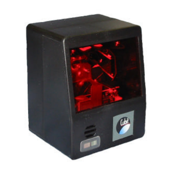
2 INTRODUCTION 2.1 INTRODUCTION Metrologic's Cubit® is a compact, omnidirectional bar code scanner that can be used as a presentation scanner or as the scanning component in Original Equipment Manufacturer (OEM) applications. Incorporating the latest in scanning technology Cubit can scan and decode all standard bar codes in any orientation. -
Page 8: General Precautions
Doing so could result in hazardous radiation exposure. The MS6520 unit is rated as a CLASS IIA laser product, as defined by The U.S. Federal Laser Product Performance Standard (FLPPS): Title 21 of the Code of Federal Regulations; Part 1000;... -
Page 9: Ms6520 Cubit Scanner History Profile
2.5 MS6520 Cubit Scanner History Profile MS6520 Revision ‘A’ / January 2000 • Light pipe removed from signal processor board and made into separate board. MS6520 Revision ‘B’ / March 2000 • Ultrasonically welded top case. MS6520 Revision ‘C’ / August 2000 •... -
Page 10: Theory & Operation
3 THEORY & OPERATION FIGURE 2.5-1 VLD LASER AND BARCODE DATA PATHS 3.1 Basic Data Decoding Sectional Summarys 3.1.1 Photodiode (Detector) Summary : 3.1.1.1 Receives the optical signal reflected off the bar code 3.1.1.2 Converts into electrical signal (current) of about 100 nanoamps 3.1.2 Pre-Amplifier Sectional Summary: 3.1.2.1 Part of the Signal processor board, usually contained in a shielded area of the PCB with the Photodiode. -
Page 11: Programmable Depth Of Field Operation Specifications
3.2 Programmable Depth of Field Operation Specifications 3.2.1 OPTIMAL LOW AND CLOSE DEPTH OF FIELD Note: The same depth of field is achieved when programming Cubit® for either Optimal Low Depth of Field or Close Depth of Field. -
Page 12: Optimal High And Normal Depth Of Field
3.2.2 OPTIMAL HIGH AND NORMAL DEPTH OF FIELD Note: The same depth of field is achieved when programming Cubit® for either Optimal High Depth of Field or Normal Depth of Field. -
Page 13: Far Depth Of Field
3.2.3 FAR DEPTH OF FIELD... -
Page 14: Board Removal & Installation
4 BOARD REMOVAL & INSTALLATION THE MS6520 ELECTRONICS ARE ESD SENSITIVE! ESD SAFETY PROCEDURES MUST BE FOLLOWED WHILE HANDLING THE MS6520 UNIT WITH ANY ELECTRONICS EXPOSED!! 4.1 Optics Bench Removal & Installation 4.1.1 Optics Bench Removal 4.1.1.1 Flip the unit over, using care not to scratch red window, so the product label is visible. -
Page 15: Optics Bench Installation
4.1.2 Optics Bench Installation 4.1.2.1 Install the four (4) grommets from the sides of the optics bench. (Figure 4.1-4) 4.1.2.2 Install the optics bench into the bottom case by grasping the signal processor board, align rubber grommets over each grommet slot and carefully insert into case. -
Page 16: Decode Board Removal & Installation
Unplug the motor cable and LED beeper wire. 4.2.1.4 Remove the ground wire from the Signal Processor Board. 4.2.1.4.1 MS6520 models, from Rev. A up to and including Rev. C with serial number ending in 0130, the ground wire is pulled off the FIGURE 4.2-1 DECODE BOARD... -
Page 17: Decode Board Installation
Signal Processor Board. (Refer to figure 4.2-2 Ground Wire shown in Decode Board Removal) 4.2.2.1.1 MS6520 models, from Rev. A up to and including Rev. C with serial number ending in 0130, the ground wire is pulled off the ground lug 4.2.2.1.2... -
Page 18: Signal Processor Board Removal & Installation
4.3 Signal Processor Board Removal & Installation 4.3.1 Signal Processor Board Removal 4.3.1.1 Open the Case and remove Optics Bench from case assembly. (Follow steps 4.1.1 Optics Bench Removal) 4.3.1.2 Disconnect J1 Ribbon cable from signal processor board J1 connector. (Figure 4.3-2) 4.3.1.3 Remove four Phillips head screws securing signal processor board from Optics bench... -
Page 19: Signal Processor Board Installation
4.3.2 Signal Processor Board Installation 4.3.2.1 Place signal processor board over Optics Bench assembly with four screw h oles aligned over screw threaded sockets. (See figure 4.3-2 in previous step.) 4.3.2.2 Secure signal processor board to optics bench using appropriate Phillips head screws. (See Figure 4.3-2 in previous step.) Ensure Ground Wire shown in Figure 4.3-2 is properly connected to signal... -
Page 20: Vld Replacement Procedure
4.4 VLD Replacement Procedure 4.4.1 VLD Removal Instructions: 4.4.1.1 Open the case to gain access inside the unit. (Follow Steps 4.1) 4.4.1.2 Carefully remove the decode board from the unit. (Follow Steps 4.2) 4.4.1.3 Remove the damaged VLD by unscrewing the two screws shown in the figure to the right. -
Page 21: Pcb Specifications
5 PCB SPECIFICATIONS 5.1 Signal Processor Board FIGURE 5.1-2 - 37823A TOP SIDE FIGURE 5.1-1 - 37823A BOTTOM SIDE VIEW VIEW 5.1.1 Signal Processor Board Functions • Receives the optical signal reflected off the bar code. • Converts received optical signal into electrical signal (current) of about 100 nanoamps. •... -
Page 22: Signal Processor Board (37823-A) Layout
5.1.2 SIGNAL PROCESSOR BOARD (37823-A) LAYOUT FIGURE 5.1-3 SIGNAL PROCESSOR BOARD 5.1.2.1 SIGNAL PROCESSOR CONNECTOR PINOUT J1 – 10 PIN Surface J2 – 3 PIN CONN Mount ZIF CONN To VLD T46 POINT LASER DRIVE T45 POINT +5VDC NO CONNECTION PHOTODIODE +5VDC +5VDC... -
Page 23: Decode Board
5.2 Decode Board FIGURE 5.2-1 - 37576D BOTTOM SIDE VIEW FIGURE 5.2-2 - 37576D TOP SIDE VIEW 5.2.1 DECODE Board Functions • Decoding algorithm decodes digital signals into universal ASCII character data. • The ASCII character data is then transmitted to the Host Computer System. •... -
Page 24: Decode Board (37576-D) Layout
5.3 DECODE BOARD (37576-D) LAYOUT FIGURE 5.3-1 DECODE BOARD 5.3.1.1 DECODE BOARD CONNECTOR PINOUT J1 – 10 PIN Surface J2 – 4 PIN CONN J3 – 10 PIN J4 – 12 PIN Surface Mount ZIF CONN Modular Jack Mount ZIF CONN MOTOR CONTROL VOLTAGE GREEN LED... -
Page 25: Led Board
5.4 LED Board FIGURE 5.4-2 - 37587D TOP SIDE FIGURE 5.4-1 - 37587D BOTTOM VIEW SIDE VIEW 5.4.1 LED Board Functions • During normal operation, the green LED is on indicating unit is ready to scan. • The red LED will turn on when the unit has successfully read a barcode. •... -
Page 26: Troubleshooting
6 TROUBLESHOOTING 6.1 AUDIBLE INDICATORS When the IS6520/MS6520 scanner is in operation, it provides audible feedback. These sounds indicate the status of the scanner. Eight settings are available for the tone of the beep (normal, 6 alternate tones and no tone). To change the tone, refer to the MetroSelect® Programming Guide MLPN 2407. -
Page 27: Failure Modes
6.2 FAILURE MODES Flashing Green and One Razzberry Tone This indicates the scanner has experienced a laser subsystem failure. Return the unit for repair at an authorized service center. Flashing Green and Red and Two Razzberry Tones This indicates the scanner has experienced a motor failure. Return the unit for repair at an authorized service center. -
Page 28: Visual Indicators
6.3 VISUAL INDICATORS There is a red LED and a green LED on IS6520/MS6520. When the scanner is on, the flashing or stationary, activity of the LEDs indicates the status of the current scan and the scanner. No Red or Green LED The LEDs will not be illuminated if the scanner is not r e ceiving power from the host or transformer. -
Page 29: Ms6520 Series Troubleshooting Guide
1 – No power is being supplied to power Omni-Quest. Use the power supply included the scanner front host. with the scanner. 1 – Contact a Metrologic Representative, if the unit will 3 beeps on power up. 1 – Non-volatile RAM failure. not hold the programmed configuration. -
Page 30: Table 3 - Troubleshooting Guide – Scanning & Reading Problems
TROUBLESHOOTING GUIDE (CONTINUED) TABLE 3 - TROUBLESHOOTING GUIDE – SCANNING & READING PROBLEMS SYMPTOMS POSSIBLE CAUSE(S) SOLUTION Unit scans, communicates and 1 – Same symbol timeout set too 1 – Adjust same symbol timeout for a longer time. beeps twice. short. -
Page 31: Table 4 - Troubleshooting Chart - Rs-232 Interface Only
TROUBLESHOOTING GUIDE (CONTINUED) TABLE 4 - TROUBLESHOOTING CHART - RS-232 INTERFACE ONLY SYMPTOMS POSSIBLE CAUSE(S) SOLUTION Powers up OK and scans OK Com port at the host is not working Check to make sure that the buad rate, data bits, stop but does not communicate or configured properly. -
Page 32: Servicing Diagrams, Parts & Pins
LEDs are also used as diagnostic indicators and mode indicators. C. Output Window Laser light emits form this aperture. D. PowerLink Cable The IS6520/MS6520 scanner has a 10-pin modular jack. The 10-pin modular plug on the PowerLink cable connects into IS6520/MS6520. -
Page 33: Cubit Model Exploded View
7.2 Cubit Model Exploded View FIGURE 7.2-1 CUBIT EXPLODED VIEW Grey Case Models Black Case Models 46-46440 GREY TOP CASE 46-46443 BLACK TOP CASE 46-46441 GREY BOTTOM CASE 46-46444 BLACK BOTTOM CASE 46-46442 DECODE PCB 46-46442 DECODE PCB 53-53000 COMM CABLE 53-53000 COMM CABLE... -
Page 34: Scanner Connector/Cable Pinout Connections
The serial # label indicates the interface enabled when the scanner is shipped from the factory. TABLE 6 - RS-232/LTPN TABLE 5 - KEYBOARD WEDGE PINOUT PINOUT IS6520-47 / MS6520-47 IS6520-41 / MS6520-41 Keyboard Wedge RS-232/LTPN Function Function Ground Ground... - Page 35 FIGURE 7.3-3 - 6 PIN DIN, FEMALE DIN, MALE Metrologic will supply an adapter cable with a 5-pin DIN male connector on one end and a 6-pin mini DIN female connector on the other. FIGURE 7.3-5 - ADAPTER CABLE FIGURE 7.3-6 - 5 PIN FIGURE 7.3-7 - 6 PIN...
-
Page 36: Ms6520 Orbit Scanner Specifications
Lines 20 Minimum Bar Width 0.145 mm (5.7 mil) Decode Capability Auto discriminates all standard bar codes; for other symbologies call Metrologic System Interfaces RS232, Light Pen Emulation, Keyboard Wedge, Stand Alone Keyboard, USB Print Contrast 35% minimum reflectance difference... -
Page 37: Electrical Characteristics
7.4.3 ELECTRICAL CHARACTERISTICS E N V I R O N M E N TA L T R I C TABLE 12 - ELECTRICAL CHARACTERISTICS Input Voltage 5 VDC + 0.25 V Power 1.0 W Operating Current 200 mA typical @ 5 VDC DC Transformers Class 2;... -
Page 38: Caution And Serial Number Labels
7.5 Caution and Serial Number Labels 7.5.1 Labels Each Cubit Scanner has an information/serial number label on the back of the unit. This label will have the unit model number, date of manufacture, in dividual unit serial number, CE and caution information. (Figure 2.5-2) FIGURE 7.5-1 TYPICAL CUBIT SERIES LABEL... -
Page 39: Ordering Replacement Parts, Servicing Information
8 Ordering Replacement Parts, Servicing Information ** To order replacement parts, contact the dealer, distributor or call Metrologic’s Customer Service Department at 1-800-ID-METRO or 1-800-436-3876. 8.1 6500 Replacement Parts Available Metrologic Description of Part Part Number 46-46510 6500 Joystick Assembly... -
Page 40: Limited Warranty
This warranty is limited to repair, replacement of Product or refund of Product price at the sole discretion of Metrologic. Faulty equipment must be returned to the Metrologic facility in Blackwood, New Jersey, U.S.A. or Puchheim, Germany. -
Page 42: Metrologic Service Locations
Fax: +34 913 273 829 Edificio Diapasón Email: info@es.metrologic.com 28037 Madrid Italy Metrologic Instruments Italia srl Tel: +39 0 51 6511978 Via Emilia 70 Fax: +39 0 51 6521337 40064 Ozzano dell’Emilia (BO) Email: info@it.metrologic.com France Metrologic Eria France SA Tel: +33 (0) 1 48.63.78.78... -
Page 43: Patents
METROLOGIC products that are physically transferred to the user, and only to the extent of METROLOGIC’S license rights and subject to any conditions, covenants and restrictions therein.”... - Page 44 Notes:...
- Page 45 Notes:...
- Page 46 Notes:...
Need help?
Do you have a question about the MS6520 and is the answer not in the manual?
Questions and answers