Metrologic VoyagerGS MS9590 Installation And User Manual
Metrologic instruments single-line hand held laser scanner installation and user's guide ms9590
Hide thumbs
Also See for VoyagerGS MS9590:
- Installation manual (2 pages) ,
- Installation and user manual (47 pages)

Related Manuals for Metrologic VoyagerGS MS9590


Summary of Contents for Metrologic VoyagerGS MS9590
- Page 1 METROLOGIC INSTRUMENTS, INC. ™ MS9590 VoyagerGS Single-Line Hand Held Laser Scanner Installation and User's Guide...
- Page 2 Copyright © 2007 by Metrologic Instruments, Inc. All rights reserved. No part of this work may be reproduced, transmitted, or stored in any form or by any means without prior written consent, except by reviewer, who may quote brief passages in a review, or provided for in the Copyright Act of 1976.
-
Page 3: Table Of Contents
ABLE OF ONTENTS Introduction Product Overview ... 1 Scanner and Accessories... 2 Scanner Components... 4 Cable Installation and Removal... 5 Labels... 6 Scanner Installation RS232 (-14)... 7 RS485 (-106)... 8 Keyboard Wedge (-47) ... 9 Stand-Alone Keyboard (-47)... 10 USB (-38 and -106) ... 11 Stand Flex Stand (PN 46-00709)... - Page 4 Design Specifications Operational... 27 Mechanical ... 28 Electrical... 28 Environmental ... 28 Scanner and Cable Terminations Scanner Pinout Connections ... 29 Cable Connector Configurations ... 30 Limited Warranty ... 32 Regulatory Compliance Safety ... 33 EMC ... 34 Patents ... 36 Index ...
-
Page 5: Product Overview
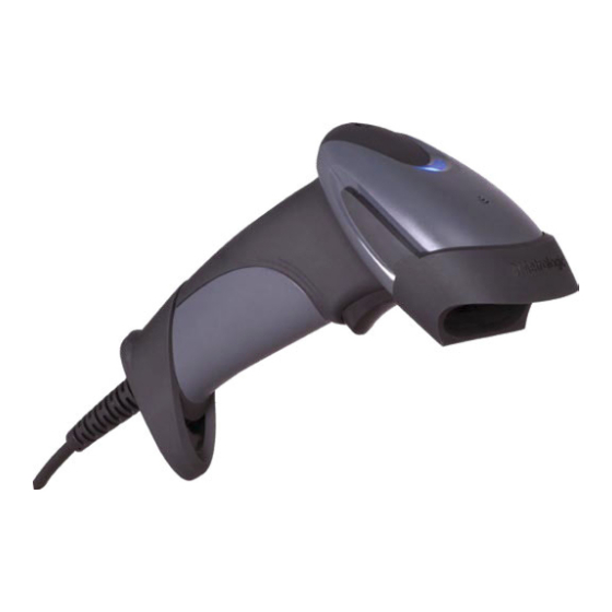
Product Overview Metrologic’s MS9590 VoyagerGS™ is the newest addition to the Voyager of hand-held laser scanners. The MS9590 is the first Voyager product to feature trigger scanning in its design. The VoyagerGS provides an aggressive solution for scanning all standard 1D bar codes in a new ergonomic form factor that maximizes comfort and reduces fatigue. -
Page 6: Scanner And Accessories
Metrologic’s Customer Service Department at 1-800-ID-METRO or 1-800-436-3876. ASIC MS9590 Bar Code Scanner MetroSelect Single-Line Configuration Guide* MS9590 Series Single-Line Hand Held Laser Scanner Installation and User’s Guide* PTIONAL CCESSORIES Flex Stand 90VAC to 255VAC, United States, Canada and Japan... - Page 7 Scanner and Accessories Part # Cable Compatibility Warning Use only MS9590 compatible product cables from the list below. Damage may occur to the scanner if incompatible cables are used. Any damage incurred from incorrect cable usage will void the limited warranty shown on page 32.
-
Page 8: Scanner Components
Cable Release Pin-Hole Laser Aperture See How to use CodeGate on page 15 10-pin RJ45, Female Socket, See Scanner Pinout Connections on page 29 See Audible Indicators on page 16 See Visual Indicators on page 17 See Visual Indicators on page 17... -
Page 9: Cable Installation And Removal
Cable Installation and Removal Important: If the cable is not fully latched, the unit can power intermittently. Plug the 10-pin RJ45 end of the cable into the 10-pin socket on the MS9590. There will be an audible click when the connector lock engages. -
Page 10: Labels
NTRODUCTION Labels Every MS9590 has a serial number label located on the underside of the scanner head and molded text on the scanner handle. The label and molded text provide important information such as the unit’s date of manufacture, serial number, CE and caution information. -
Page 11: Scanner Installation
RS232 (-14) Turn off the host device. Plug the 10-pin RJ45 end of the PowerLink cable into the 10-pin socket on the MS9590. There will be an audible click when the connector lock engages. Connect the 9-pin D-type connector of the PowerLink cable to the proper COM port on the host device. -
Page 12: Rs485 (-106)
Scan the bar code below to activate the RS485 interface. ³ USB is the default communication protocol for an MS9590-106. If the recall defaults bar code is scanned after the unit has been configured for RS485, the scanner will revert to the USB default communication protocol. -
Page 13: Keyboard Wedge (-47)
MetroSet2 for instructions on changing the scanner’s factory default configuration. Powering the MS9590-47 directly from the host device may cause interference with the operation of the scanner or the host device. Not all host devices supply the same current through the keyboard port. -
Page 14: Stand-Alone Keyboard (-47)
MetroSet2 for instructions on changing the scanner’s factory default configuration. Powering the MS9590-47 directly from the host device may cause interference with the operation of the scanner or the host device. Not all host devices supply the same current through the keyboard port. -
Page 15: Usb (-38 And -106)
See caution on page 6. The MS9590-38 and the MS9590-106 meet the requirements for Full Speed USB hardware. These interfaces also support all emulation types previously supported by Metrologic in Low Speed USB scanners. -
Page 16: Stand
TAND Flex Stand Components (PN 46-00709) Item Cradle Coupler Cradle Flexible Shaft Screw Cap Stand Base ¼" - 20 x ⅜" Flat Head Phillips Screw, 100° Undercut #8 Round Head Wood Screw M3 -.5 x 20 mm, Pan Head Phillips Screw M3 Flat Washer M3 Split Lock Washer Flexible Shaft Cover... -
Page 17: Assembly
TAND Flex Stand Assembly (PN 46-00709) Figure 11. Stand Assembly... -
Page 18: Optional Fixed Mount
TAND Optional Flex Stand Fixed Mount (PN 46-00709) In the kit, two #8 wood screws have been provided for fixed mount applications. When choosing the stand location, make sure to consider the front orientation of the stand (indicated in Figure 12). On a centerline, drill two #39 pilot holes in the countertop spaced 125 mm (4.92") apart. -
Page 19: Scanner Operation
CANNER PERATION Default Modes of Operation There are two default modes of operation available with the MS9590. In-Stand, Automatic Activation Mode • The laser is activated upon object detection in the IR activation area. • Bar code data is automatically decoded and transmitted. -
Page 20: Indicators Audible
NDICATORS Audible During operation, the MS9590 provides audible feedback that indicates the status of the scanner and latest scan. Eight settings are available for the tone of the beep (normal, 6 alternate tones and no tone). To change the beeper tone, refer to the MetroSelect Single-Line Configuration Guide or MetroSet2’s help... -
Page 21: Visual
LEDs indicates the status of the scanner and the current scan. All LEDs are Off The LEDs will not be illuminated if the scanner is not receiving power from the host or transformer. The scanner is in idle mode and CodeGate is enabled. -
Page 22: Failure Modes
Return the scanner for repair to an authorized service center. Three Beeps – On Power Up If the scanner beeps 3 times on power up, verify the host and scanner are set to the same communication protocol. If the host and the scanner's communication protocol match, then, the non-volatile memory (NovRAM) that holds the scanner's configuration may have failed. -
Page 23: Configuration Modes
ONFIGURATION The MS9590 has three modes of configuration. • Bar Codes The MS9590 can be configured by scanning the bar codes located in the ® MetroSelect Single-Line Configuration Guide ( This manual can be downloaded FREE at www.metrologic.com. ® •... -
Page 24: Upgrading The Flash Rom Firmware
PGRADING THE The MS9590 VoyagerCG is part of Metrologic's line of scanners with flash upgradeable firmware. The upgrade process requires a new firmware file supplied to the customer by a customer service representative and Metrologic's MetroSet2 software . A personal computer running Windows 95 or greater with an available RS232 serial or USB port is also required to complete the upgrade. -
Page 25: Depth Of Field
EPTH OF IELD .127 mils Figure 16. Depth of Field vs. Bar Code Element Width Specifications are subject to change without notice. INIMUM LEMENT 10.4 IDTH... -
Page 26: Ir Activation Range
IR A CTIVATION ANGE The MS9590 has an optional built in object detection sensor that instantly turns on the scanner's laser when an object is presented within the scanner's IR activation area. Refer to the MetroSelect Single-Line Configuration Guide for information on configurable IR activation range options. -
Page 27: Applications And Protocols
Scanner Identifier MS9590 The MS9590 Keyboard Wedge Series (-47) is designed for keyboard emulation only. Many RS232 configurable functions available in other Metrologic scanners are also available as keyboard wedge functions. The following items are the most important selectable options specific to the... -
Page 28: Troubleshooting Guide
Some host systems cannot supply enough current to power Voyager. A power supply may be needed. Set the host and scanner to the same communication protocol. Contact a Metrologic service representative. Contact a Metrologic service representative. - Page 29 Solution Verify that the bar code being scanned falls into the configured criteria. The scanner defaults to a minimum of 3 character bar code. If the unit is setup to support ACK/NAK, RTS/CTS, XON/XOFF or D/E, verify that the host cable and host are supporting the handshaking properly.
- Page 30 It may be necessary to try this in both settings. Enable the Caps Lock detect feature of the scanner to detect whether the PC is operating in Caps Lock. Try operating the scanner in Alt mode. Check to make sure that the baud...
-
Page 31: Design Specifications
Beeper Operation: Visual Indicators: Default Settings Specifications are subject to change without notice. MS9590 Series Specifications Visible Laser Diode 650 nm ± 10 nm 0.809 mW (peak) 560 µsec 0 mm - 305 mm ( 0" – 12" ) with a 0.330 mm (13 mil) bar code... -
Page 32: Mechanical
For regulatory compliance information see pages 33 – 35. NVIRONMENTAL Temperature: Humidity: Light Levels: Shock: Contaminants: Specifications are subject to change without notice. MS9590 Series Specifications 160 mm (6.30") 41 mm (1.60") 65 mm (2.56") 25.4 mm (1.00") 100 mm (3.93") 150g 5VDC ± 0.25V... -
Page 33: Scanner And Cable Terminations
CANNER AND ABLE Scanner Pinout Connections The MS9590 scanner interfaces terminate to a 10-pin modular jack. The serial number label indicates the interface enabled when the scanner is shipped from the factory. MS9590-14 RS232 Function Ground Transmit RS232 Output Receive RS232 Input... -
Page 34: Cable Connector Configurations
CANNER AND ABLE Cable Connector Configurations (Host End) RS232 PowerLink Cable 53-53000x-3 Function Shield Ground RS232 Transmit Output RS232 Receive Input DTR Input/Light Pen Source Signal Ground Light Pen Data (DSR Out for -14 interfaces) CTS Input RTS Output +5VDC USB Cables 53-53813x-N-3, 53-53809x-N-3 Function... - Page 35 CANNER AND ABLE Cable Connector Configuration (Host End) Keyboard Wedge Cable 53-53802x-3 Function Keyboard Clock Keyboard Data No Connect Power Ground +5 Volts DC Function PC Data No Connect Power Ground +5 Volts DC PC Clock No Connect Metrologic will supply an adapter cable with a 5-pin DIN male connector on one end and a 6-pin mini DIN female connector on the other.
-
Page 36: Limited Warranty
The MS9590 VoyagerGS™ series scanners are manufactured by Metrologic at its Blackwood, New Jersey, U.S.A. facility and at its Suzhou, China facility. The MS9590 series scanners have a five (5) year limited warranty from the date of manufacture. Metrologic warrants and represents that all MS9590 series scanners are free of all defects in material, workmanship and design, and have been produced and labeled in compliance with all applicable U.S. -
Page 37: Regulatory Compliance Safety
Never attempt to look at the laser beam, even if the scanner appears to be nonfunctional. Never open the scanner in an attempt to look into the device. Doing so could result in hazardous laser light exposure. The use of optical instruments with the laser equipment will increase eye hazard. -
Page 38: Emc
Class A Devices The following is applicable when the scanner cable is greater in length than 3 meters (9.8 feet) when fully extended: Les instructions ci-dessous s’appliquent aux cables de scanner dépassant 3 métres (9.8 pieds) de long en extension maximale:... - Page 39 Class B Devices The following is applicable when the scanner cable is less than 3 meters (9.8 feet) in length when fully extended: Les instructions ci-dessous s’appliquent aux cables de scanner ne dépassant pas 3 métres (9.8 pieds) de long en extension maximale:...
-
Page 40: Patents
ATENTS This METROLOGIC product may be covered by, but not limited to, one or more of the following US Patents: US Patent No. 4,958,984; 5,081,342; 5,260,553; 5,340,971; 5,340,973; 5,424,525; 5,468,951; 5,484,992; 5,525,789; 5,528,024; 5,591,953; 5,616,908; 5,627,359; 5,661,292; 5,777,315; 5,789,730; 5,789,731; 5,811,780; 5,825,012; 5,828,048;... -
Page 41: Index
NDEX AC ... see power accessories ...2, 3 adapter ...3 Beep ...see indicators blue LED...see indicator cable... 2–3, 24–26 adapter ...3 communication ... 1, 2–3, 5, 7–11, 20, 26, 29–31 installation...5 MVC...3, 8 pin assignments...29–31 caution...6, 33 labels ...6 laser...6, 33 CE ...see caution CodeGate ...1, 15, 17 communication ...24–26... - Page 42 NDEX repair ...32 RMA ...32 RS232 ... see interface RS485 ... see interface safety...33 SELV ...see caution serial number...6 specifications...27, 28 stand ... 2, 12–15 termination...29–31 tones ...17 troubleshooting...24–26 UL ... see caution USB ...see interface ventilation... 28 voltage ... 2, 28, see caution warranty ...
- Page 44 November 2007 Printed in the USA 0 0 - 0 5 1 5 0 C...
Need help?
Do you have a question about the VoyagerGS MS9590 and is the answer not in the manual?
Questions and answers