Table of Contents
Advertisement
Quick Links
Advertisement
Table of Contents

Subscribe to Our Youtube Channel
Related Manuals for thomann Stairville Robohead X-3 LED


Summary of Contents for thomann Stairville Robohead X-3 LED
- Page 1 Robohead X-3 LED moving head user manual...
- Page 2 Musikhaus Thomann e.K. Treppendorf 30 96138 Burgebrach Germany Telephone: +49 (0) 9546 9223-0 E-mail: info@thomann.de Internet: www.thomann.de 28.11.2012...
-
Page 3: Table Of Contents
Table of contents Table of contents General notes............................... 5 Safety instructions............................. 8 Features............................... 13 Installation..............................15 Starting up..............................21 Connections and operating elements................... 24 Operation..............................28 7.1 Starting the device........................... 28 7.2 Main menu............................29 7.3 Settings menu........................... 38 7.4 Gobos..............................43 7.5 Functions in 11-channel DMX mode.................. - Page 4 Table of contents Troubleshooting............................61 Technical specifications........................63 Protecting the environment......................64 moving head...
-
Page 5: General Notes
General notes General notes This user manual contains important information on safe operation of the device. Read and follow all safety notes and all instructions. Save this manual for future reference. Make sure that it is available to all persons using this device. If you sell the device, include the manual for the next owner. - Page 6 General notes Signal word Meaning DANGER! This combination of symbol and signal word indicates an immediate dangerous situation that will result in death or serious injury if it is not avoided. WARNING! This combination of symbol and signal word indicates a possible dangerous situation that can result in death or serious injury if it is not avoided.
- Page 7 General notes Warning signs Type of danger Warning – high-voltage. Warning – hot surface. Warning – suspended load. Warning – danger zone. Robohead X-3 LED...
-
Page 8: Safety Instructions
Safety instructions Safety instructions Intended use This device is intended to be used as moving-head spotlight. Use the device only as described in this user manual. Any other use or use under other operating conditions is considered to be improper and may result in personal injury or property damage. No liability will be assumed for damages resulting from improper use. - Page 9 Safety instructions DANGER! Electric shock caused by high voltages inside Within the device there are areas where high voltages may be present. Never remove any covers. There are no user-serviceable parts inside. DANGER! Electric shock caused by short-circuit Always use proper ready-made insulated mains cabling (power cord) with a pro‐ tective contact plug.
- Page 10 Safety instructions WARNING! Eye damage caused by high light intensity Never look directly into the light source. WARNING! Risk of epileptic shock Strobe lighting can trigger seizures in photosensitive epilepsy. Sensitive persons should avoid looking at strobe lights. WARNING! Risk of burns The surface of the device can become very hot during operation.
- Page 11 Safety instructions CAUTION! Risk of injury due to movements of the device The head of the device can move quickly (pan, tilt) and can produce very bright light. This is also valid immediately after you turn on the device, when the device operates in automatic mode or under remote control and when you turn off a DMX controller that is connected to the device.
- Page 12 Safety instructions NOTICE! Operating conditions This device has been designed for indoor use only. To prevent damage, never expose the device to any liquid or moisture. Avoid direct sunlight, heavy dirt, and strong vibrations. NOTICE! Power supply Before connecting the device, ensure that the input voltage (AC outlet) matches the voltage rating of the device and that the AC outlet is protected by a residual current circuit breaker.
-
Page 13: Features
Features Features This Moving Head is specially suited for professional lighting, e.g. at events, on rock stages, in theatres, musicals or discos. Special features of the device: Three axes of movement with 8 or 16 bit resolution: – Tilt (540 °) –... - Page 14 Features Shutter frequency: 0…13 Hz Automatic position correction moving head...
-
Page 15: Installation
Installation Installation Unpack and check carefully there is no transportation damage before using the unit. Keep the equipment packaging. To fully protect the device against vibration, dust and moisture during transportation or storage use the original packaging or your own packaging material suitable for transport or storage, respectively. - Page 16 Installation CAUTION! Risk of injury due to movements of the device The head of the device can move quickly (pan, tilt) and can produce very bright light. This is also valid immediately after you turn on the device, when the device operates in automatic mode or under remote control and when you turn off a DMX controller that is connected to the device.
- Page 17 Installation NOTICE! Possible damage caused by movements of the device Always ensure that enough space is free around the device for the movements of the head (pan, tilt). NOTICE! Possible data transmission errors For error-free operation make use of dedicated DMX cables and do not use ordi‐ nary microphone cables.
- Page 18 Installation DMX connections The unit offers a 3-pin XLR socket for DMX output and a 3-pin XLR plug for DMX input. Please refer to the drawing and table below for pin assignment. Ground, shielding DMX data (–) DMX data (+) moving head...
- Page 19 Installation Mounting options You can install the unit on the ceiling or on the floor. A mounting bracket and the necessary screws are included. The device is not suitable for wall mounting. The threads on the bottom side of the housing allow the secure attachment of the bracket or truss clamps.
- Page 20 Installation A Threads for the supplied bracket or truss clamps B Safety-rope openings moving head...
-
Page 21: Starting Up
Starting up Starting up Establish all connections as long as the unit is switched off. Use the shortest possible high- quality cables for all connections. Robohead X-3 LED... - Page 22 Starting up Connections in DMX mode Connect the DMX input of the device to the DMX output of a DMX controller or another DMX device. Connect the output of the first DMX device to the input of the second one, and so on to form a daisy chain.
- Page 23 Starting up DMX indicator If the device and the DMX controller are in operation, the DMX indicator shows an incoming DMX signal at the input. Connections in master/slave When you configure a group of devices in master/slave mode, the first unit will control the mode other units for an automatic, sound-activated, synchronized show.
-
Page 24: Connections And Operating Elements
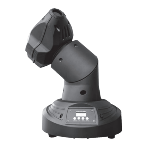
Connections and operating elements Connections and operating elements moving head... - Page 25 Connections and operating elements 1 Light aperture with projection lens. 2 Moving head. 3, 4 Moving arm. 5 Device base. 6 Display. 7 [MODE/ESC] button Activates the main and the settings menu and changes between the menu items. Closes an open menu without saving the changes.
- Page 26 Connections and operating elements 10 [ENTER] button Selects an option of the respective operating mode, confirms the set value. 11 DMX indicator This LED indicates an incoming DMX signal. 12 INPUT DMX input. 13 OUTPUT DMX output. 14 Carrying handle. 15 POWER IEC chassis connector with fuse holder.
- Page 27 Connections and operating elements Axes of movement The figure below shows the three axes of movement of the device. Robohead X-3 LED...
-
Page 28: Operation
Operation Operation 7.1 Starting the device CAUTION! Risk of injury due to movements of the device The head of the device can move quickly (pan, tilt) and can produce very bright light. This is also valid immediately after you turn on the device, when the device operates in automatic mode or under remote control and when you turn off a DMX controller that is connected to the device. -
Page 29: Main Menu
Operation 7.2 Main menu Press [MODE/ESC] (for about 30 seconds if running DMX controlled) to open the main menu. Press [MODE/ESC] again to select a menu item. Use the [UP] and [DOWN] buttons to change the respectively indicated value. When the display shows the desired value, press [ENTER]. - Page 30 Operation DMX address Repeatedly press [MODE/ESC] until the display shows ‘dxxx’ . Now you can set the number of the first DMX channel to be used by the device (DMX address). Use [UP] and [DOWN] to select a value between 1 and 512. When the display shows the desired value, press [ENTER] to confirm the setting and then [MODE/ESC] to proceed to the next menu item.
- Page 31 Operation Operating mode ‘Auto show’ Repeatedly press [MODE/ESC] until the display shows ‘NASL’ . Use [UP] and [DOWN] to select one of the preprogrammed shows. Press [ENTER] to start operation in the selected operating mode. Display with opened menu Display after confirmation Operating mode with [ENTER] NASL...
- Page 32 Operation Display with opened menu Display after confirmation Operating mode with [ENTER] NStc ‘crUn’ Automatic show type 3 (mid speed), in stand alone opera‐ tion or as master in master / slave operation SLAv ‘Son’ Unit operates as slave und follows the master device Pan inversion 1 Repeatedly press [MODE/ESC] until the display shows ‘PAN’...
- Page 33 Operation Tilt inversion Repeatedly press [MODE/ESC] until the display shows ‘tit’ . Use [UP] and [DOWN] to select between ‘rtit’ (inverse direction of inclination) and ‘tit’ (normal direction of inclination). This setting refers to the rotation of the axis between the two parts of the rotating arm. When the display shows the desired value, press [ENTER] to confirm the setting and then [MODE/ESC] to proceed to the next menu item.
- Page 34 Operation Operating mode ‘DMX’ Repeatedly press [MODE/ESC] until the display shows ‘11CH’ . Use [UP] and [DOWN] to select one of the following DMX operating modes: 11 channel or 16 channel. This setting is only rele‐ vant if the device is controlled via DMX. When the display shows the desired value, press [ENTER] to confirm the setting and then [MODE/ESC] to proceed to the next menu item.
- Page 35 Operation Tilt range Repeatedly press [MODE/ESC] until the display shows ‘ti27’ . Use [UP] and [DOWN] to determine the Tilt range. Choose between ‘ti54’ (Tilt range = 540°), ‘ti36’ (Tilt range = 360°) and ‘ti18’ (Tilt range = 180°). This setting refers to the rotation of the axis between the two parts of the rotating arm.
- Page 36 Operation Loading default values Repeatedly press [MODE/ESC] until the display shows ‘LoAd’ . Press [ENTER] to reset all values that can be adjusted in the main menu to factory defaults. moving head...
- Page 37 Operation Overview (main menu) Robohead X-3 LED...
-
Page 38: Settings Menu
Operation 7.3 Settings menu Press [MODE/ESC] for about five seconds to activate the settings menu. Use [UP] or [DOWN] to input the device password 2323. Then the [UP] button will change the number at the cursor position, the [DOWN] button moves the cursor to the next digit. Press [ENTER] when all digits are entered. - Page 39 Operation Rotation preset (pan 1 offset) Activate the settings menu. Repeatedly press [MODE/ESC] until the display shows ‘Pxxx’ . Use the [UP] / [DOWN] buttons to enter a value between 0 and 255, until the head is in the desired home position.
- Page 40 Operation Rotation preset (pan 2 offset) Activate the settings menu. Repeatedly press [MODE/ESC] until the display shows ‘Hxxx’ . Use the [UP] / [DOWN] buttons to enter a value between 0 and 255, until the head is in the desired home position.
- Page 41 Operation Gobo wheel preset Activate the settings menu. Repeatedly press [MODE/ESC] until the display shows ‘Gxxx’ . Use the [UP] / [DOWN] buttons to enter a value between 0 and 255, until the Gobo wheel is in the desired home position. When the display shows the desired value, press [ENTER] to confirm the setting and then [MODE/ESC] to proceed to the next menu item.
- Page 42 Operation Overview (settings menu) moving head...
-
Page 43: Gobos
Operation 7.4 Gobos Robohead X-3 LED... -
Page 44: Functions In 11-Channel Dmx Mode
Operation 7.5 Functions in 11-channel DMX mode Channel Value Function 0…255 Rotation (pan) around axis 1 (0° up to the maximum value of pan range: 180°, 360° or 540°) 0…255 Inclination (tilt) (0° up to the maximum value of Tilt range: 180°, 360° or 540°) 0…255 Rotation (pan) around axis 2 (0°... - Page 45 Operation Channel Value Function 56…63 64…71 White + dark blue 72…79 Dark blue + yellow 80…87 Yellow + pink 88…95 Pink + green 96…103 Green + peachblow 104…111 Peachblow + blue 112…119 Blue + red 120…127 Red + white 128…191 Rainbow effect clockwise, increasing speed 192…255 Rainbow effect counter-clockwise, increasing speed...
- Page 46 Operation Channel Value Function 4…7 Open 8…215 Strobe effect, increasing speed 216…255 Open Gobo wheel 0…7 Open 8…15 Gobo 2 16…23 Gobo 3 24…31 Gobo 4 32…39 Gobo 5 40…47 Gobo 6 48…55 Gobo 7 56…63 Gobo 8 64…71 Gobo 8 shake, increasing speed moving head...
- Page 47 Operation Channel Value Function 72…79 Gobo 7 shake, increasing speed 80…87 Gobo 6 shake, increasing speed 88…95 Gobo 5 shake, increasing speed 96…103 Gobo 4 shake, increasing speed 104…111 Gobo 3 shake, increasing speed 112…119 Gobo 2 shake, increasing speed 120…127 Open 128…191...
- Page 48 Operation Channel Value Function 240…255 Yo-yo effect (bouncing gobo) with alternating rotation direction, increasing length of rota‐ tion intervals Prism 0…7 Not in use 8…255 Prism effect 0…255 Focus Special functions 0…7 Not in use 8…15 Blackout during pan-1, pan-2 or tilt movement 16…23 No blackout during pan-1, pan-2 or tilt movement 24…31...
- Page 49 Operation Channel Value Function 48…55 No blackout during gobo wheel movement 56…87 Not in use 88…95 Blackout during movement 96…103 Pan 1, pan 2 and tilt reset 104…111 Not in use 112…119 Colour wheel reset 120…127 Gobo wheel reset 128…135 Gobo rotation reset 136…143 Prism reset...
- Page 50 Operation Channel Value Function 0…7 Not in use 8…23 Programme 1 24…39 Programme 2 40…55 Programme 3 56…71 Programme 4 72…87 Programme 5 88…103 Programme 6 104…119 Programme 7 120…135 Programme 8 136…151 Sound-control 1 152…167 Sound-control 2 168…183 Sound-control 3 184…199 Sound-control 4 moving head...
-
Page 51: Functions In 16-Channel Dmx Mode
Operation Channel Value Function 200…215 Sound-control 5 216…231 Sound-control 6 232…247 Sound-control 7 248…255 Sound-control 8 7.6 Functions in 16-channel DMX mode Channel Value Function 0…255 Rotation (pan) around axis 1 (0° up to the maximum value of pan range: 180°, 360° or 540°) 0…255 Inclination (tilt) (0°... - Page 52 Operation Channel Value Function 0…255 Fine tuning of inclination (tilt) 0…255 Fine tuning of rotation (pan) around axis 2 0…255 Speed of pan-1, pan-2 and tilt movement Colour wheel 0…7 White 8…15 Dark blue 16…23 Yellow 24…31 Pink 32…39 Green 40…47 Peachblow 48…55...
- Page 53 Operation Channel Value Function 72…79 Dark blue + yellow 80…87 Yellow + pink 88…95 Pink + green 96…103 Green + peachblow 104…111 Peachblow + blue 112…119 Blue + red 120…127 Red + white 128…191 Rainbow effect clockwise, increasing speed 192…255 Rainbow effect counter-clockwise, increasing speed Shutter 0…3...
- Page 54 Operation Channel Value Function 216…255 Open 0…255 Dimmer (0 to 100 %) Gobo-Rad 0…7 Open 8…15 Gobo 2 16…23 Gobo 3 24…31 Gobo 4 32…39 Gobo 5 40…47 Gobo 6 48…55 Gobo 7 56…63 Gobo 8 64…71 Gobo 8 shake, increasing speed 72…79 Gobo 7 shake, increasing speed moving head...
- Page 55 Operation Channel Value Function 80…87 Gobo 6 shake, increasing speed 88…95 Gobo 5 shake, increasing speed 96…103 Gobo 4 shake, increasing speed 104…111 Gobo 3 shake, increasing speed 112…119 Gobo 2 shake, increasing speed 120…127 Open 128…191 Rainbow effect clockwise, increasing speed 192…255 Rainbow effect counter-clockwise, increasing speed Gobo rotation...
- Page 56 Operation Channel Value Function 240…255 Yo-yo effect (bouncing gobo) with alternating rotation direction, increasing length of rota‐ tion intervals Special functions 0…7 Not in use 8…15 Blackout during pan-1, pan-2 or tilt movement 16…23 No blackout during pan-1-, pan-2- or tilt movement 24…31 Blackout during colour wheel movement 32…39...
- Page 57 Operation Channel Value Function 104…111 Not in use 112…119 Colour wheel reset 120…127 Gobo wheel reset 128…135 Gobo rotation reset 136…143 Prism reset 144…151 Focus reset 152…159 All channel reset 160…255 Not in use Built-in programmes 0…7 Not in use 8…23 Programme 1 24…39...
- Page 58 Operation Channel Value Function 56…71 Programme 4 72…87 Programme 5 88…103 Programme 6 104…119 Programme 7 120…135 Programme 8 136…151 Sound-control 1 152…167 Sound-control 2 168…183 Sound-control 3 184…199 Sound-control 4 200…215 Sound-control 5 216…231 Sound-control 6 232…247 Sound-control 7 248…255 Sound-control 8 moving head...
- Page 59 Operation Channel Value Function Prism 0…7 Not in use 8…255 Prism effect 0…255 Focus Robohead X-3 LED...
-
Page 60: Cleaning
Cleaning Cleaning Optical lenses Clean the exterior of accessible optical lenses periodically to optimise light output. The fre‐ quency of cleaning depends on the operating environment: wet, smoky or particularly dirty surroundings can cause more accumulation of dirt on the optics of the device. Clean with a soft cloth using normal glass cleaning products. -
Page 61: Troubleshooting
Troubleshooting Troubleshooting NOTICE! Possible data transmission errors For error-free operation make use of dedicated DMX cables and do not use ordi‐ nary microphone cables. Never connect the DMX output to audio devices such as mixers or amplifiers. In the following we list a few common problems that may occur during operation. We give you some suggestions for easy troubleshooting: Robohead X-3 LED... - Page 62 4. Check whether the DMX cables lie near or adjacent to high voltage cables, which could cause damage or inter‐ ference with a DMX interface circuit. If the procedures recommended above do not succeed, please contact our Service Center. You can find the contact information at www.thomann.de. moving head...
-
Page 63: Technical Specifications
Technical specifications Technical specifications Number of DMX channels 11, 16 50 W Operating voltage supply AC 230 V , 50 Hz Power consumption 145 W Fuse 5 mm × 20 mm, 2 A, 250 V, fast acting Dimensions (W × D × H) 276 mm ×... -
Page 64: Protecting The Environment
Protecting the environment Protecting the environment Disposal of the packaging mate‐ rial For the transport and protective packaging, environmentally friendly materials have been chosen that can be supplied to normal recycling. Ensure that plastic bags, packaging, etc. are properly disposed of. Do not just dispose of these materials with your normal household waste, but make sure that they are collected for recycling. - Page 65 Notes Robohead X-3 LED...
- Page 66 Notes moving head...
- Page 68 Musikhaus Thomann e.K. · Treppendorf 30 · 96138 Burgebrach · Germany · www.thomann.de...
Need help?
Do you have a question about the Stairville Robohead X-3 LED and is the answer not in the manual?
Questions and answers