Table of Contents
Advertisement
Quick Links
Advertisement
Table of Contents

Subscribe to Our Youtube Channel
Related Manuals for thomann Starville EP1080


Summary of Contents for thomann Starville EP1080
- Page 1 EP1080 Event Panel 1080 RGB LED floodlight user manual...
- Page 2 Musikhaus Thomann Thomann GmbH Hans-Thomann-Straße 1 96138 Burgebrach Germany Telephone: +49 (0) 9546 9223-0 E-mail: info@thomann.de Internet: www.thomann.de 10.08.2015, ID: 359649...
-
Page 3: Table Of Contents
Table of contents Table of contents General notes............................... 5 1.1 Further information........................... 6 1.2 Notational conventions........................7 1.3 Symbols and signal words....................... 8 Safety instructions..........................10 Features............................... 15 Installation..............................16 Starting up..............................20 Connections and operating elements................... 23 Operating..............................29 7.1 Starting the device........................... - Page 4 Table of contents 7.6 Mode 3 functions..........................42 7.7 Mode 4 functions..........................43 7.8 Mode 5 functions..........................44 7.9 Mode 6 functions..........................48 7.10 Mode 7 functions........................... 49 Technical specifications........................50 Plug and connection assignment....................51 Troubleshooting............................53 Cleaning............................... 56 Protecting the environment......................
-
Page 5: General Notes
General notes General notes This manual contains important instructions for the safe operation of the unit. Read and follow the safety instructions and all other instructions. Keep the manual for future reference. Make sure that it is available to all those using the device. If you sell the unit please make sure that the buyer also receives this manual. -
Page 6: Further Information
General notes 1.1 Further information On our website (www.thomann.de) you will find lots of further information and details on the following points: Download This manual is also available as PDF file for you to download. Use the search function in the electronic version to find the topics of Keyword search interest for you quickly. -
Page 7: Notational Conventions
General notes 1.2 Notational conventions This manual uses the following notational conventions: Letterings The letterings for connectors and controls are marked by square brackets and italics. Examples: [VOLUME] control, [Mono] button. Displays Texts and values displayed on the device are marked by quotation marks and italics. Examples: ‘24ch’... -
Page 8: Symbols And Signal Words
General notes 1.3 Symbols and signal words In this section you will find an overview of the meaning of symbols and signal words that are used in this manual. Signal word Meaning DANGER! This combination of symbol and signal word indicates an immediate dangerous situation that will result in death or serious injury if it is not avoided. - Page 9 General notes Warning signs Type of danger Warning – high-voltage. Warning – suspended load. Warning – danger zone. EP1080 Event Panel 1080 RGB...
-
Page 10: Safety Instructions
Safety instructions Safety instructions Intended use This device is intended to be used as an electronic illumination effect using LED technics. The device is designed for professional use and is not suitable for use in households. Use the device only as described in this user manual. Any other use or use under other operating con‐ ditions is considered to be improper and may result in personal injury or property damage. - Page 11 Safety instructions Safety DANGER! Danger for children Ensure that plastic bags, packaging, etc. are disposed of properly and are not within reach of babies and young children. Choking hazard! Ensure that children do not detach any small parts (e.g. knobs or the like) from the unit.
- Page 12 Safety instructions DANGER! Electric shock caused by short-circuit Always use proper ready-made insulated mains cabling (power cord) with a pro‐ tective contact plug. Do not modify the mains cable or the plug. Failure to do so could result in electric shock/death or fire. If in doubt, seek advice from a regis‐ tered electrician.
- Page 13 Safety instructions NOTICE! Risk of fire Do not cover the device nor any ventilation slots. Do not place the device near any direct heat source. Keep the device away from naked flames. NOTICE! Operating conditions This device has been designed for indoor use only. To prevent damage, never expose the device to any liquid or moisture.
- Page 14 Safety instructions NOTICE! Power supply Before connecting the device, ensure that the input voltage (AC outlet) matches the voltage rating of the device and that the AC outlet is protected by a residual current circuit breaker. Failure to do so could result in damage to the device and possibly injure the user.
-
Page 15: Features
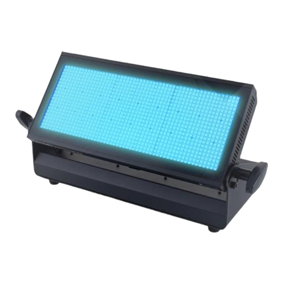
Features Features The LED floodlight is particularly suitable for lighting applications in clubs and discotheques, on rock stages, in theatres and musicals. It can also be used for effect lighting of stage back‐ grounds. Special features of the device: 1080 tri-colour SMD LEDs Control via DMX (seven different modes) and via buttons and display on the unit Eight preprogrammed automatic shows Sound control... -
Page 16: Installation
Installation Installation Unpack and carefully check that there is no transportation damage before using the unit. Keep the equipment packaging. To fully protect the device against vibration, dust and moisture during transportation or storage use the original packaging or your own packaging material suitable for transport or storage, respectively. - Page 17 Installation NOTICE! Risk of overheating Always ensure sufficient ventilation. The ambient temperature must always be below 40 °C (104 °F). NOTICE! Possible data transmission errors For error-free operation make use of dedicated DMX cables and do not use ordi‐ nary microphone cables. Never connect the DMX input or output to audio devices such as mixers or ampli‐...
- Page 18 Installation Please note that this device must not be connected to a dimmer. LED floodlight...
- Page 19 Installation Mounting options The quick lock openings on the housing bottom are used for secure attachment of the sup‐ plied Omega brackets. Here you can connect flight adapters (such as C-hooks). The safety cable must be guided through this safety eyelet Ä...
-
Page 20: Starting Up
Starting up Starting up Establish all connections as long as the unit is switched off. Use the shortest possible high- quality cables for all connections. LED floodlight... - Page 21 Starting up Connections in DMX mode Connect the DMX input of the device to the DMX output of a DMX controller or another DMX device. Connect the output of the first DMX device to the input of the second one, and so on to form a daisy chain.
- Page 22 Starting up DMX indicator If the unit is in DMX mode and a DMX controller is connected and turned on, the [DMX] LED lights. Connections in master/slave When you configure a group of devices in master/slave mode, the first unit will control the mode other units for an automatic, sound-activated, synchronized show.
-
Page 23: Connections And Operating Elements
Connections and operating elements Connections and operating elements Rear panel EP1080 Event Panel 1080 RGB... - Page 24 Connections and operating elements 1 LED panel with adjustable tilt angle. 2 Locking screws for the LED panel. 3 Operating panel. 13 [DMX OUT] DMX output in three and five-pole design. 14 [DMX IN] DMX input in three and five-pole design. 15 [MIC] Microphone for sound control.
- Page 25 Connections and operating elements 18 [Mains IN] Blue lockable powerCON input socket (NAC3FA) for mains connection. 19 Fuse holder. If the fuse blows, replace it with a new fuse of the same type. You must first disconnect the device from the power supply.
- Page 26 Connections and operating elements Operating panel LED floodlight...
- Page 27 Connections and operating elements 4 Display. 5 [SLAVE] The red control LED indicates that the device is in ‘Slave’ mode. 6 [SOUND] The green control LED indicates that the Sound Control function is enabled. 7 Button [ENTER] Selects an option of the respective operating mode, confirms the set value. 8 Button Navigates upwards in a menu list.
- Page 28 Connections and operating elements 11 [MASTER] The yellow control LED indicates that the device is in ‘Master’ mode. 12 [DMX] The red control LED indicates that a signal is present at the DMX input. LED floodlight...
-
Page 29: Operating
Operating Operating 7.1 Starting the device Connect the device to the power supply to start operation. After a few seconds, the fans start and the display indicates that a reset is in progress. The device is then ready for use. The dis‐ play shows the operating mode that was selected when the unit was last powered off. - Page 30 Operating Operating mode ‘Preprog‐ A preprogrammed automatic show can only be activated when the unit is operating in stand- rammed automatic show’ alone mode or as master in a master / slave combination. This setting is only relevant if the device is not controlled via DMX.
- Page 31 Operating DMX address This setting is only relevant if the device is controlled via DMX. Press [MENU] repeatedly until the display shows ‘Addr’ . Press [ENTER]. Now you can set the number of the first DMX channel to be used by the device (DMX address). to select a value between 1 and 512.
- Page 32 Operating Press [ENTER] to apply the settings. Press [MENU] for about one second or wait for about eight seconds to close the menu without changes. LED floodlight...
- Page 33 Operating DMX mode This setting is only relevant if the device is controlled via DMX. Press [MENU] repeatedly until the display shows ‘ChNd’ . Press [ENTER]. Now use select one of the following DMX operating modes: Mode ‘Nod1’ (4 channels) ‘Nod2’...
- Page 34 Operating Operating mode ‘Master / Salve’ This setting is only relevant if the device is working in a Master / Slave configuration and is not controlled via DMX. Press [MENU] repeatedly until the display shows ‘SLNd’ . Press [ENTER]. Now use choose from the following options: ‘NASt’...
- Page 35 Operating Colour transition This setting is only relevant if the device is Master in a Master / Slave configuration and is not controlled via DMX. Press [MENU] repeatedly until the display shows ‘CoNd’ . Press [ENTER]. Now use choose between fast colour transition ( ‘CoJP’ , colour jump) and gradual colour transition ( ‘CoFd’...
- Page 36 Operating Blackout Press [MENU] repeatedly until the display shows ‘bLNd’ . Press [ENTER]. Now use blackout the LEDs ( ‘YES’ ) or to turn them back on again ( ‘no’ ). Press [ENTER] to apply the settings. Press [MENU] for about one second or wait for about eight seconds to close the menu without changes.
- Page 37 Operating Display blackout Press [MENU] repeatedly until the display shows ‘Led’ . Press [ENTER]. To enable the Blackout function press repeatedly until the display shows ‘oFF’ . Press [ENTER]. From now on the display goes out if you do not press a button within a period of two minutes.
- Page 38 Operating White balance Press [MENU] repeatedly until the display shows ‘bALA’ . Press [ENTER]. With you can now select the primary colour you want to set: ‘red’ , ‘Gree’ , ‘bLue’ . Press [ENTER] again. With you can now set a value between 125 and 255 for the selected colour.
-
Page 39: Menu Overview
Operating 7.3 Menu overview EP1080 Event Panel 1080 RGB... - Page 40 Operating LED floodlight...
-
Page 41: Mode 1 Functions
Operating 7.4 Mode 1 functions Channel Value Function 0 … 255 Intensity Red (0 % to 100 %) 0 … 255 Intensity Green (0 % to 100 %) 0 … 255 Intensity Blue (0 % to 100 %) Dimmer / Strobe 0 …... -
Page 42: Mode 2 Functions
Operating 7.5 Mode 2 functions Channel Value Function 0 … 255 Intensity Red (0 % to 100 %) 0 … 255 Intensity Green (0 % to 100 %) 0 … 255 Intensity Blue (0 % to 100 %) 0 … 255 Dimmer (0 % to 100 %) 7.6 Mode 3 functions Channel... -
Page 43: Mode 4 Functions
Operating Channel Value Function Dimmer / Strobe 0 … 160 Dimmer (0 % to 100 %) 161 … 255 Strobe effect, increasing speed 7.7 Mode 4 functions Channel Value Function 0 … 255 Intensity Red (0 % to 100 %), if channel 4 = 0 … 199 0 …... -
Page 44: Mode 5 Functions
Operating Channel Value Function 128 … 199 Strobe effect, increasing speed 200 … 255 Automatic colour change with gradual transition, increasing speed 7.8 Mode 5 functions Channel Value Function 0 … 255 Intensity Red (0 % to 100 %), if channel 5 = 0 … 7 0 …... - Page 45 Operating Channel Value Function 8 … 15 Colour 1 16 … 23 Colour 2 24 … 30 Colour 3 31 … 38 Colour 4 39 … 46 Colour 5 47 … 54 Colour 6 55 … 61 Colour 7 62 … 69 Colour 8 70 …...
- Page 46 Operating Channel Value Function 109 … 115 Colour 14 116 … 123 Colour 15 124 … 131 Colour 16 132 … 139 Colour 17 140 … 146 Colour 18 147 … 154 Colour 19 155 … 162 Colour 20 163 … 169 Colour 21 170 …...
- Page 47 Operating Channel Value Function 209 … 216 Colour 27 217 … 223 Colour 28 224 … 231 Colour 29 232 … 239 Colour 30 240 … 247 Colour 31 248 … 255 Colour 32 Strobe effect 0 … 7 LEDs off 8 …...
-
Page 48: Mode 6 Functions
Operating Channel Value Function 190 … 231 Strobe effect with fast rising and slow drop of brightness, increasing speed 232 … 239 LEDs on, no strobe effect 240 … 247 Random Strobe effect 248 … 255 LEDs on, no strobe effect 7.9 Mode 6 functions Channel Value... -
Page 49: Mode 7 Functions
Operating 7.10 Mode 7 functions Channel Value Function 0 … 14 LEDs off 16 … 31 32 … 47 Yellow 48 … 63 Green 64 … 79 Cyan 80 … 95 Blue 96 … 111 Magenta 112 … 127 White 128 …... -
Page 50: Technical Specifications
Technical specifications Technical specifications Number of DMX channels 1, 3, 4 or 6 channels, according to operating mode Illuminant 1080 tri-colour SMD LEDs Dispersion angle approx. 135° Operating supply voltage AC 100 … 240 V , 50/60 Hz Power consumption 247 W Fuse 5 mm ×... -
Page 51: Plug And Connection Assignment
Plug and connection assignment Plug and connection assignment Introduction This chapter will help you select the right cables and plugs to connect your valuable equip‐ ment so that a perfect light experience is guaranteed. Please take our tips, because especially in ‘Sound & Light’ caution is indicated: Even if a plug fits into a socket, the result of an incorrect connection may be a destroyed DMX controller, a short circuit or ‘just’... - Page 52 Plug and connection assignment DMX connections A five-pin XLR socket serves as DMX output, a five-pin XLR plug serves as DMX input. The drawing below and the table show the pin assignment of a matching coupling. Assignment Ground (shielding) Signal inverted (DMX–, ‘cold’) Signal (DMX+, ‘hot’) unused / second connection (DMX–) unused / second connection (DMX+)
-
Page 53: Troubleshooting
Troubleshooting Troubleshooting NOTICE! Possible data transmission errors For error-free operation make use of dedicated DMX cables and do not use ordi‐ nary microphone cables. Never connect the DMX input or output to audio devices such as mixers or ampli‐ fiers. In the following we list a few common problems that may occur during operation. - Page 54 Troubleshooting Symptom Remedy The unit does not work, no light, Check the mains connection and the main fuse. the display is dark Apparently no function despite Check if the unit is in DMX mode or in ‘slave’ mode. If so, proper power supply check the unit in another mode.
- Page 55 Troubleshooting If the procedures recommended above do not succeed, please contact our Service Center. You can find the contact information at www.thomann.de. EP1080 Event Panel 1080 RGB...
-
Page 56: Cleaning
Cleaning Cleaning Optical lenses Clean the optical lenses, that are accessible from the outside, regularly in order to optimize the light output. The frequency of cleaning depends on the operating environment: wet, smoky or particularly dirty surroundings can cause more accumulation of dirt on the optics of the device. -
Page 57: Protecting The Environment
Protecting the environment Protecting the environment Disposal of the packaging mate‐ rial For the transport and protective packaging, environmentally friendly materials have been chosen that can be supplied to normal recycling. Ensure that plastic bags, packaging, etc. are properly disposed of. Do not just dispose of these materials with your normal household waste, but make sure that they are collected for recycling. - Page 58 Notes LED floodlight...
- Page 60 Musikhaus Thomann · Hans-Thomann-Straße 1 · 96138 Burgebrach · Germany · www.thomann.de...
Need help?
Do you have a question about the Starville EP1080 and is the answer not in the manual?
Questions and answers