
Related Manuals for Hague Quality Water Hydroclean HC3


Summary of Contents for Hague Quality Water Hydroclean HC3
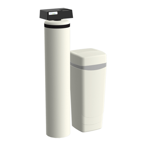
- Page 1 ’ ’...
- Page 2 This warranty does not cover any labor or service call costs incurred with respect to the removal and replacement of any defective part(s). Hague Quality Water International will not be liable for, nor will it pay any labor or service call charges incurred or expended with respect to this warranty.
-
Page 3: Table Of Contents
Contents Owner Information .............................. 4 General Information ............................4 Getting Maximum Efficiency From the Appliance ................... 5 Five-Button Controller ............................ 6 Customer Settings ............................8 Checklist Before Installation ........................... 9 Installation and Maintenance Information ......................9 Precautions ..............................10 Installation Steps and Start-Up Procedures ....................11 Bypass Valve ............................... -
Page 4: Owner Information
WNER NFORMATION General Information Congratulations on choosing a superior Hague water treatment appliance! Soon you and your family will be enjoying clean, clear water. Use this guide to attain the maximum benefit from your appliance. As an owner, you may find the first few pages to be the most helpful in solving your needs. -
Page 5: Getting Maximum Efficiency From The Appliance
Getting Maximum Efficiency From the Appliance To achieve the maximum benefit and performance The appliance may be disinfected with 5.25% from this appliance, familiarize yourself with this sodium hypochlorite, which is the active manual and the appliance. ingredient in household chlorine bleach. To disinfect the appliance, add chlorine bleach The salt level should always be at least 1/3 full. -
Page 6: Five-Button Controller
Five-Button Controller This appliance features a five-button controller with an LCD display. The controller can be used to view the appliance’s status, perform regenerations, and change settings. An independent Hague dealer should set the Service Settings Gal. Remain 00850 LCD Display during installation of the appliance. - Page 7 Five-Button Controller, Cont. Controller Part Function Buttons Cont. The Change, Select, Display, and Scroll Back buttons are used when changing Customer Settings and Service Settings. Display The Display button is used to enter programming modes and also to save a value and display the next value to be changed.
-
Page 8: Customer Settings
Customer Settings Service Settings must be set before Customer Settings; Service Settings should be set during installation of the appliance. To set Customer Settings, press and hold the Display button for about five seconds while “Customer Setting” displays. Release the button when “Set Time” displays. If the setting displayed is correct, press Display to move to the next setting. -
Page 9: Checklist Before Installation
NSTALLATION AND AINTENANCE NFORMATION Checklist Before Installation Refer to this checklist before installation. Water Quality—If the water supply contains sand, sulfur, bacteria, iron bacteria, tannins, algae, oil, acid, or other unusual substances, consider pre-treating the water to remove these contaminants before the water supply enters the appliance, unless the appliance is represented as being capable of treating these contaminants in its specifications. -
Page 10: Precautions
Precautions Comply with all state and local, building, plumbing, and electrical codes. Install the appliance before the water heater. Install the appliance after the pressure tank on well-water installations. Install a pressure-reducing valve if the inlet pressure exceeds 70 psi (4.8 bar). Examine the inlet line to ensure water will flow through it freely and that the inlet pipe is sized correctly. -
Page 11: Installation Steps And Start-Up Procedures
Installation Steps and Start-Up Procedures Prepare the Placement Area Step 1 Make sure the placement area is clean. Turn off the electricity and water supply to the water heater. For gas water heaters, turn the gas cock to “Pilot.” Examine the inlet plumbing to ensure that the pipe is not plugged with lime, iron, or any other substance. -
Page 12: Turn Off Water Supply
Installation Steps and Start-Up Procedures, Cont. Turn Off Water Supply Step 2 Turn off the water supply. Open the hot and cold water taps to depressurize the lines. Connect Water Lines Step 3 Connect water lines in compliance with all state and local, building, plumbing, and electrical codes. - Page 13 Installation Steps and Start-Up Procedures, Cont. Check for Leaks Step 8 Close all faucets. Check all lines and connections for leaks. If leaks are found: 1. Turn off the main water supply. 2. Open a cold water faucet to depressurize the lines. 3.
-
Page 14: Bypass Valve
Installation Steps and Start-Up Procedures, Cont. Complete the Installation Step 13 Ensure that the bypass valve is left in the Service position. See Figure 4. Ensure the water supply is on. Open the inlet valve and turn on the electricity to the water heater. For gas water heaters, return the gas cock to “On.”... -
Page 15: Blending Valve
Blending Valve In some situations, the blending valve may be used to decrease water softness. The amount of hardness blended back into the water line is determined by the hardness of the incoming water and the setting of the blending valve. Where extremely hard water is present, the blending valve may only need to be “cracked” open. Where the incoming water has relatively low levels of hardness, the blending valve will need to be opened further. -
Page 16: Service Settings
Service Settings To program Service settings on the controller, press and hold the Select and Display buttons while “Service Settings” is displayed until “Set Language Eng” is displayed. Programming Service Settings is similar to programming Customer Settings (see Customer Settings for programming details). The values that can be set are listed below. - Page 17 Service Settings, Cont. Display Meaning Possible Values Comments 72–96 hr Regen A way to force regeneration at No (or Yes, for iron) See 72–96 Hour regularly scheduled intervals Regeneration Backwash 1 01.0 Number of minutes the first backwash 00.0 to 99.9 Set to the nearest tenth of cycle lasts a minute...
- Page 18 Service Settings, Cont. Mode 1 (Timer) and Mode 2 (Demand Delayed) Setting Chart This section provides guidance for using different service settings to achieve the desired capacity. HC3 25* HC3 25CX** HC3 35* HC3 48* HC3 64* HC3 105* #1 Salt Setting Backwash 1 (minutes) Brine/Rinse (minutes) Backwash 2 (minutes)
-
Page 19: Hc3 1Nf Replenishment Procedure
HC3 1NF Replenishment Procedure The neutralizing media that adjusts the pH level of the water must be refilled periodically. Typically, this media is calcite and is available from Hague. To refill the neutralizing media, measure the appliance’s media bed depth upon installation (factory freeboard). Use this measurement to determine the amount of media to add to maintain optimum performance of the HC3 1NF. - Page 20 HC3 1NF Replenishment Procedure, Cont. Add Replenishment Media Step 4 Weigh the replenishment media. Place the funnel into the tank. Pour the media into the funnel to fill the tank with the measured amount of media. Replace Control Valve Step 5 Make sure the threads of the tank are clean.
-
Page 21: Hc3 2If Iron Filter Sizing Formula
HC3 2IF Iron Filter Sizing Formula This iron filter may be programmed to regenerate every 1–12 days. Select the frequency based on the amount of iron in the water and the number of people in the household. For optimum performance, program the water softener to regenerate first, followed by the iron filter. -
Page 22: Iron Filter And Potassium Permanganate Feeder Installation Guide
Iron Filter and Potassium Permanganate Feeder Installation Guide Important: This iron filter is capable of treating a combination of undesirable constituents in the water (iron, manganese, and/or hydrogen sulfide). However, the filter must be applied within the operating limits stated in the Filter Specifications in this manual. -
Page 23: Complete The Installation
Iron Filter and Potassium Permanganate Feeder Installation Guide, Cont. Connect Lines Step 3 Connect the 3/8-inch tubing to the brine valve on the filter by pushing the tube to the stop. Pull back on the tubing to install the red locking clip behind the collet. Connect the tubing to the feeder. -
Page 24: Assembly And Parts
Assembly and Parts Hook-Up/Cover Assembly Figure 9: Controller Tab Lock Detail Figure 8: Hook-Up/Cover Assembly Part # Description Quantity 53008 Valve Cover (Rain Resistant) without Label (optional) 53500 Valve Cover (Rain Resistant) with Label (standard) 53505 Valve Cover Assembly with Window (optional on Custom Valves) 53501 Valve Assembly w/O-Ring 90837... - Page 25 Assembly and Parts, Cont. Standard Brine Tank Assembly Figure 11: Standard 24" x 50" Brine Tank Figure 10: Standard Brine Tank Assembly (HC3 64 and 105) (HC3 25, 25CX, 35, and 48) Part # Description Quantity Part # Description Quantity 54006 Brine Tank Cover BT2450...
- Page 26 Assembly and Parts, Cont. Optional Brine Tank Assembly Figure 13: Potassium Permanganate Feeder Figure 12: Optional Brine Tank Assembly (P/N PT1424) Part # Description Quantity BT055 Brine Tank Cover BT1833-HWC Brine Tank C0700 Overflow Fitting 93811-26.5 Air Check/Draw Tube Assembly C0800 Brine Well C0650...
- Page 27 Assembly and Parts, Cont. Resin Tank Assembly Part # Description BT844 Thermo Jacket – 44" BT948 Thermo Jacket - 48" BT1047 Thermo Jacket - 47" BT1054 Thermo Jacket - 54" C1400 Thermo Foam - 8" C1430 Thermo Foam - 9" C1480 Thermo Foam - 10"...
- Page 28 Assembly and Parts, Cont. Valve Assembly Figure 15: Valve Assembly Part # Description Quantity 93809 End Cap Screw 93870 End Cap Screw 90614 Drain End Cap Assembly 93808 O-Ring 93835 Spacer Tube 93838 I/O Adapter O-Ring 54600 Bypass Valve Assembly 95301T-JG* Drive End Cap Assembly 95302T-BWO* Drive End Cap Assembly-Backwash Only...
- Page 29 Assembly and Parts, Cont. Brine Valve Housing Assembly Concave side Static O-Ring Figure 16: Brine Valve Housing Assembly Part # Description Quantity 53511 Piston Assembly (includes O-Ring & Spring) 90821 O-Ring 53510 Housing (Not sold separately) 90843 0.5 gpm Flow Control 93805 O-Ring 93247...
- Page 30 Assembly and Parts, Cont. Bypass Valve Assembly Figure 17: Bypass Valve Assembly Part # Description Quantity 54600 Bypass Valve Assembly (also includes items 2-15) 90827 O-Ring 90222 Blending Dial 90252 Cap - Blending Dial 90802 Screw 90812 Tubing 4.0-inch 90226 Test Port Valve 90828 O-Ring...
- Page 31 Assembly and Parts, Cont. Bypass Valve Assembly Cont. 90252 Blending The Cap should be held in place by the three 1/2-inch self-tapping screws and be in the proper Dial Cap orientation. 90222 Blending The Dial permits the addition of “untreated water” into the soft water outlet. It is closed when pointing Dial toward the Main Control Valve and open when pointing toward the inlet side.
- Page 32 Assembly and Parts, Cont. Drive End Cap Assembly Figure 18: Drive End Cap Assembly Part # Description Quantity 90802 Screw, self-tapping 90217 Drive Motor 93891 1/4-inch Hex Nut 93238 Drive Gear 90809 Screw, self-tapping 93219 Piston Slide Cam Cover 93217 Piston Slide Cam 93583 Drive End Cap...
- Page 33 Assembly and Parts, Cont. Drive End Cap Assembly Cont. 90217 Drive The Motor is held in place by two 1/2-inch self-tapping screws. The screws should be “snug.” The brass Motor pinion gear on the Motor should engage the plastic Drive Gear. The wires should be securely fastened to the Control.
- Page 34 Assembly and Parts, Cont. Injector Assembly Figure 19: Injector Assembly Part # Description Quantity 93223 Injector Throat 93223-Red* Injector Throat 53224 Injector Nozzle with Over-Mold Gasket 53224-Red* Injector Nozzle with Over-Mold Gasket 93806 O-Ring 53235 Injector Cap 93504 Entire Assembly (all of the above parts) 93504-Red* Entire Assembly (all of the above parts) * For use on 12-inch (30.5 cm) and 14-inch (35.6 cm) diameter softener tanks and 2IF only...
- Page 35 Assembly and Parts, Cont. Drain End Cap Assembly Figure 20: Drain End Cap Assembly Part # Description Quantity 93808 O-Ring 90268 Drain End Cap H2086-XX* Drain Line Flow Control 90267 Retainer 90614-XX* Entire Assembly (all the above parts) * Must specify drain line flow control size. X.X indicates the backwash rate in gpm. Example: 90614 – 2.4 90268 Drain End Cap The Drain End Cap seals the left opening on the Main Control Valve.
- Page 36 Assembly and Parts, Cont. Optional 3/4-inch and 1-inch I/O Adapter Assemblies with Blending Valve Figure 21: 3/4-inch I/O Adapter Assembly with Blending Valve Part # Description Quantity 93521 3/4-inch I/O Adapter Assembly (includes parts 1–9) 93521-1 1-inch I/O Adapter Assembly (not shown) 93521-BWO 3/4-inch I/O Backwash Only Assembly (not shown) 93521-1-BWO...
- Page 37 Assembly and Parts, Cont. Safety Shutoff Assembly Figure 22: Safety Shutoff Assembly Part # Description Quantity 54226 Safety Shutoff (See Figure 23) 56018 Float 54160 Air Check/Draw Tube 54625 Entire Assembly (all of the above parts) HC3 Owner’s Manual 12/11/2013...
-
Page 38: Brine Valve Elbow Installation
Assembly and Parts, Cont. Brine Valve Elbow Installation 3/8" Plastic Gripper 3/8" Nut 3/8" Retainer Sleeve 3/8" Plastic Insert Safety Shutoff Valve 3/8" Poly Tube Hex Nut Wrist Pin 1/2" Retainer Sleeve 1/2" Plastic Gripper 1/2" Nut Air Check/Draw Tube Figure 23: Brine Valve Elbow Installation Part # Description... -
Page 39: Troubleshooting
Troubleshooting Problem Possible Cause Solution No soft water after No salt in brine tank Add salt regeneration Sediment in brine tank has plugged the brine Remove the brine line and flush clean line and air check/draw tube Remove the air check/draw tube and flush with clean water. - Page 40 Troubleshooting, Cont. Problem Possible Cause Solution Appliance stays in Controller not attached properly Make sure the controller is pushed all the way regeneration onto the drive end cap Defective magnet disk Replace magnet disk Foreign object in main control valve Remove foreign object(s) from the main control valve Broken valve assembly.
-
Page 41: Water Conditioner Specifications
Water Conditioner Specifications Five-Button Dual Mode Controller HC3 25 HC3 25CX HC3 35 HC3 48 HC3 64 HC3 105 Max Compensated Hardness–gpg (g/L) 60 (1.0) 25 (0.4) 90 (1.5) 110 (1.9) 120 (2.0) 130 (2.2) Iron in solution–ppm Minimum pH–standard units Tannin–ppm Sulfur–ppm–SulfurStat Maximum Chlorine–ppm... -
Page 42: Filter Specifications
Filter Specifications Five-Button Dual Mode Controller— HC3 2IF HC3 1CF HC3 1NF HC3 1MMF Special Series Capacity–ppm 8,000 Sulfur H S–ppm Iron in solution–ppm Max Compensated Hardness –gpg (g/L) 5 (0.08) Minimum pH – standard units Manganese Media type Activated Carbon Calcite/Corosex Multi-Grade Greensand... - Page 43 Notes...
- Page 44 HC3 has these third-party listings: Tested and certified by WQA according to CSA B483.1. Hague Quality Water, International 4343 S. Hamilton Rd. Groveport, OH 43125 Phone: 614-836-2115 LITHO USA ©2013 53120 RV1213–Ver. 2.4...
Need help?
Do you have a question about the Hydroclean HC3 and is the answer not in the manual?
Questions and answers
The system does not shut off and runs continuously. The gears seem to sees up.
The Hague Quality Water HC3 system could run continuously and the gears may seize up due to a jam in the drive system. This can cause the keyed opening between the Drive Gear and the Slide Cam to become rounded, allowing the gear to turn without moving the Piston Slide Cam. This issue requires clearing the jam and replacing both the Drive Gear and the Piston Slide Cam.
This answer is automatically generated
After backwash,I have to run water a while to get salt taste out of water
The Hague Quality Water Hydroclean HC3 may have a salt taste after backwashing if the brine and rinse cycle is not set correctly or if insufficient rinsing occurs. The brine/rinse cycle duration determines how thoroughly the salt is flushed from the system. If the rinse time is too short, residual salt may remain, causing a salty taste in the water. Adjusting the brine/rinse cycle duration to ensure complete flushing can help resolve this issue.
This answer is automatically generated
how do i get to chnage # of people to reset it ?