Table of Contents
Advertisement
Quick Links
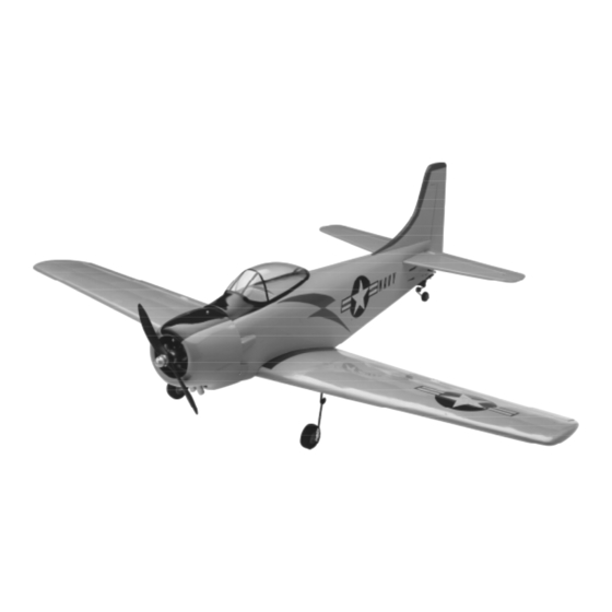
4 0 - 4 6 S i z e S t a n d - o f f S c a l e A . R . F.
Instructions for Final Assembly
The Skyraider was designed to be a replacement for the naval dive bombers that were in use in the
1940's. It was felt that one aircraft could be designed that would be able to fill that role and much more,
and that reducing the crew to a single pilot would result in weight savings and speed increases, both
factors that would enable the aircraft to carry more ordinance more effectively.
This was exactly what happened when the prototype was first flown on March 18, 1945. The
Skyraider was a single seat ground attack aircraft. It carried two 20mm cannons and up to 6000lbs. of
externally stored weapons. The Skyraider was powered by one Wright Cyclone radial engine producing
2400 horsepower. Because of it's successes in the later parts of the Vietnam war and throughout the
Korean war, the U.S. Navy called the Skyraider "the best and most effective close support airplane in
the world."
Now you too can experience the same feeling with your new Global Skyraider ARF. The Global
Skyraider is built by master craftsmen, utilizing the finest grades of balsa, light ply, foam and fiberglass.
It's covered using heat shrink polyester material, just like you would buy at your local hobby shop.
Want to install retracts into your new Skyraider? We've already installed the hardwood rails, cut out
the wheel wells and strut channels to make it as easy as possible. Don't want to install retracts?
We've provided all the necessary hardware to install fixed main gear. In fact, we've provided all of the
hardware to finish the Skyraider. Fuel tank, wheels, pushrods, pull-pull cables, clevises and much
more. It's all in the kit. Don't worry about trying to find an aftermarket fiberglass cowl either. We've
provided a one piece fiberglass cowl that's even prepainted to match the covering! With this kind of
quality prefabrication, you'll be in the air and strafing ground targets in no time!
Version
V1.0
9-99 MTN
1
All Contents © Copyright 1999
Advertisement
Table of Contents

Related Manuals for Global Hobby Skyraider


Summary of Contents for Global Hobby Skyraider
- Page 1 Instructions for Final Assembly The Skyraider was designed to be a replacement for the naval dive bombers that were in use in the 1940's. It was felt that one aircraft could be designed that would be able to fill that role and much more, and that reducing the crew to a single pilot would result in weight savings and speed increases, both factors that would enable the aircraft to carry more ordinance more effectively.
-
Page 2: Table Of Contents
Kit Contents..............2 Mounting the Engine to the Firewall Additional Items Required..........3 For 4 Cycle Engines Only........15 Tools and Supplies Needed..........3 Fuel Tank...............16 Field Support Equipment Needed........3 Stopper Assembly...........16 Stopper Installation..........17 Metric Conversion Chart..........3 Fuel Tank Installation..........17 Wing Assembly..............4 Throttle Linkage............18 Hinging the Ailerons..........4 Installing the Pushrod Housing......18 Installing the Aileron Servos........4... -
Page 3: Kit Contents
This instruction manual is designed to help you build a straight, great flying airplane. Please read this manual thoroughly before beginning assembly of your new Skyraider ARF. Use the parts listing below to identify and separate all of the parts before beginning assembly. -
Page 4: Additional Items Required
{1} Hitec 4 or More Channel Radio w/5 Servos FOR 4 CYCLE ENGINE {2} Cirrus 12” Servo Extensions # 444713 {1} Cirrus Y-Harness # 444728 {1} Magnum XL .52 - .80 Four Cycle Engine {1} Dubro Heat Shrink Tubing # 440 {1} Propeller To Suit Engine {1} Dubro Foam Rubber # 513 {1} Thunderbolt Glow Plug # 115490... -
Page 5: Wing Assembly
Please trial fit all the parts. Make sure you have the correct parts and that they fit and are aligned properly before gluing! This will assure proper assembly. Since the Skyraider is hand made from natural materials, every airplane is unique and minor adjustments may have to be made. However, you should find the fit superior and assembly simple. -
Page 6: Installing The Servo Hatches
7) Plug the two servos into your radio receiver blocks into place on the servo tray. Allow the epoxy to fully cure before proceeding. and center them both. Make sure the aileron trim tab on your transmitter is centered as well. Install the It is important that you use epoxy in this situa- rubber isolation grommets and brass collets onto both tion. -
Page 7: Installing The Dihedral Brace
The heat shrink tubing will prevent the plugs 25) Using a ruler and a pen, locate and mark from coming apart during assembly and more the centerline of the plywood dihedral brace. Draw importantly during flight. If you don't use heat shrink one vertical line at this location on each side. -
Page 8: Optional Fixed Main Gear
30) Slide the dihedral brace into the plywood Do not remove the covering from over the pre- cut optional retract mounting holes, strut chan- box up to the centerline. Remove any excess epoxy before it dries using a paper towel and rubbing alco- nels or wheel wells. -
Page 9: Optional Retract Main Gear
5) Repeat steps # 2 - # 4 for installing the sec- ond retract mechanism. PARTS REQUIRED INSTALLING THE RETRACT SERVO {2} 50mm Diameter Wheels {2} Molded Plastic Retract Gear Covers 6) Install the rubber isolation grommets and brass collets onto your retract servo. Place the servo INSTALLING THE RETRACT MECHANISMS onto the preinstalled rails in the servo compartment 1) Using a modeling knife, remove the cover-... -
Page 10: Installing The Retract Gear Covers
15) Rotate the servo wheel 180º so the retracts 11) Using a ruler, measure the distance your re- are in the full down and locked position. Use pliers tract mechanism moves from the full up and locked and carefully bend each of the wires to prevent them position to the full down and locked position. -
Page 11: Installing The Wheels
19) When satisfied with the fit, glue the plastic 2) Place the wing into the wing saddle and tem- gear covers into place using RC256 Canopy Glue. porarily secure it in place using the two 4mm x 40mm Hold the covers in place using masking tape until the machine screws and 4mm plastic flat washers. -
Page 12: Installing The Wing Fairing
the fuselage sides out to the stabilizer's tips. Both INSTALLING THE WING FAIRING measurements should be equal when the stabilizer is 10) Using a modeling knife, or Lexan Canopy centered. See figure # 8 below. Scissors, cut out the plastic wing fairing along the molded scribe line. -
Page 13: Mounting The Horizontal Stabilizer
7) On the top and bottom of the stabilizer, draw a line where it and the fuselage sides meet. Do this on both the right and left sides. PARTS REQUIRED {1} Vertical Stabilizer with Rudder 8) Remove the stabilizer. Using the lines you {3} C/A Hinges drew as a guide, remove the covering from between ALIGNING THE VERTICAL STABILIZER... -
Page 14: Mounting The Vertical Stabilizer
2) Insert one 2mm wheel collar into the molded MOUNTING THE VERTICAL STABILIZER recess in the tail wheel tiller arm. Align the hole in 5) When you are sure that everything is aligned the wheel collar with the hole in the side of the tiller correctly, mix up a generous amount of Kwik Bond arm. -
Page 15: Installing The Tail Wheel
For two cycle engines, we recommend a .40 - .53 displacement en- gine mounted sideways. The Skyraider will accept a two cycle engine with a stock muffler, but trimming of the cowl to fit the muffler will be necessary. For a... -
Page 16: Mounting The Engine To The Firewall
If using an engine equipped with a remote needle 9) On the two horizontal lines you just drew, valve we recommend mounting the needle valve measure and place two marks 5/8” to the left of the to the engine after installing the motor mount/engine vertical centerline and two marks 1-1/16”... -
Page 17: Fuel Tank
18) Hold the motor mount assembly up to the 14) Using a ruler and a pen, measure up from firewall and double check that the four intersecting the bottom of the firewall 1-1/2” and place two lines line up with the four predrilled holes in the mo- marks. -
Page 18: Stopper Installation
4) Push one 4mm x 28mm prebent nylon vent Photo # 36 Vent tube through the nylon backplate and through the rub- Tube ber stopper until it protrudes 3/8” from the front of Fill the stopper. Tube 5) Using a modeling knife, remove part of the second nylon vent tube as shown below. -
Page 19: Throttle Linkage
Photo # 37 PARTS REQUIRED Pushrod Wire {1} 1.5mm x 380mm Pushrod Wire {1} 3mm x 270mm Nylon Pushrod Housing INSTALLING THE PUSHROD HOUSING 1) Mark and drill a hole through the firewall for Make Bends the throttle pushrod housing using a 1/8” drill bit. Position the hole level with the throttle arm and just to the outside edge of the motor mounting beam. -
Page 20: Throttle Connection
PARTS REQUIRED PARTS REQUIRED {1} Stranded Wire Cable {1} Adjustable Servo Connector {2} Nylon Adjustable Control Horns INSTALLING THE SERVO CONNECTOR {4} Nylon Clevises {1} 3mm x 50mm Threaded Rod 1) Install one adjustable servo connector through {2} 3mm Flat Washers the third hole out from the center of one servo arm. - Page 21 7) Using wire cutters, cut the length of wire cable 12) Thread two nylon clevises onto the two re- exactly in half. If the wire begins to unravel, care- maining threaded couplers. For security, thread the fully twist the wire back into shape and apply a drop clevises on no less than 5/16”.
-
Page 22: Elevator Pushrod
Make sure that when you install the pushrod, it is installed below the rudder cables and that the PARTS REQUIRED cables do not get wrapped around the pushrod wires {1} 740mm Split Elevator Pushrod Assembly or dowel. {2} Nylon Clevises {1} Adjustable Servo Connector Assembly 6) Thread two nylon clevises onto the threaded {2} Nylon Control Horn w/Backplates... -
Page 23: Aileron Linkages
12) With both elevator halves and the servo arm INSTALLING THE AILERON LINKAGES centered, tighten the set screw in the adjustable servo 4) Thread one nylon clevis onto one 2mm x connector. Remove the excess wire using wire cut- 250mm threaded wire. For security thread the clevis ters. -
Page 24: Canopy
PARTS REQUIRED PARTS REQUIRED {1} Molded Clear Canopy {1} Molded Fiberglass Cowling {2} Molded Plastic Cowl Fairings CANOPY PREPARATION {3} 10mm x 10mm x 20mm Hardwood Blocks {3} 3mm x 10mm Wood Screws 1) Using a sharp knife or Lexan Canopy Scis- {1} Nylon Fuel Filler Housing sors, trim out the canopy along the molded scribe lines. -
Page 25: Installing The Fuel Filler
7) Remove the cowl and measure the distances 12) Push the fuel filler housing into the hole and from the guide marks on the fuselage to the center of snap the nylon snap ring over the housing from the the cowl mounting blocks. inside of the cowl. -
Page 26: Final Assembly
3) Using a 1/16” drill bit, drill a hole through the 16) Using 220 grit sandpaper with a sanding side of the fuselage, near the receiver, for the antenna block, carefully sand the edges of both fairings to exit. Route the antenna out of the fuselage and se- smooth. -
Page 27: Balancing
Moving the clevis toward the control surface will in- point forward will cause the airplane to be more stable, crease the amount of throw. but less responsive. Do not fly the Skyraider be- yond the recommended balance range or an un- controllable crash could result! -
Page 28: Preflight Check
2) Check every bolt and every glue joint in the C) Check the rudder. Looking from behind Skyraider to ensure that everything is tight and well the airplane, move the rudder stick to the right. The bonded. This should include all of the control sur- rudder should move to the right. -
Page 29: Notes
In the air, the Skyraider flies like any other sport aero- _ _ _ _ _ _ _ _ _ _ _ _ _ _ _ _ _ _ _ _ _ _ _ _ _ _ _ _ _ _ _ _ _ _ _ _ _ _ _ _ _ _ _ _ _ _ _ _ _ _ _ _ _ _ _ _ _ _ _ _ _ _ _ _ _ _ _ _ _ _ _ _ _ _ _ _ _ _ _ _ _ _ _ _ _ _ batic plane. -
Page 30: Trim Chart
After you have test flown and done the initial trim changes to the aircraft, use the Trim Chart below to begin trimming your airplane. Following and adhering to this chart will result in the ability to diagnose trim problems and correct those problems using the simple adjustments shown below. Making these observations and related corrections will result in a truer, straighter and better flying airplane. -
Page 31: Product Evaluation
Simply fold this form on the dotted lines, seal with tape and mail it to us. Do not use staples and make sure our address faces out. 7) Was any of the assembly difficult for you? If 1) Kit: Global Skyraider 40 - 46 ARF yes, please explain. 2) Where did you learn about this kit? - Page 32 Post Office will not deliver without proper postage Global Hobby Distributors Attn: Customer Service Department 18480 Bandilier Circle Fountain Valley, CA. 92728 Fold along dotted line...
Need help?
Do you have a question about the Skyraider and is the answer not in the manual?
Questions and answers