Advertisement
Quick Links
Global guarantees this kit to be free from defects in both material and workmanship, at the date of purchase. This does not
cover any component parts damaged by use, misuse or modification. In no case shall Global's liability exceed the
original cost of the purchased kit.
In that Global has no control over the final assembly or material used for final assembly, no liability shall be assumed for
any damage resulting from the use by the user of the final user-assembled product. By the act of using the final user-
assembled product, the user accepts all resulting liability.
The Global Freestyle ARF is distributed exclusively by Global Hobby Distributors 18480 Bandilier Circle, Fountain Valley, CA 92728
All contents copyright © 2001, Global Hobby Distributors Version V1.0 February 2001
1
Advertisement

Related Manuals for Global Hobby Freestyle


Summary of Contents for Global Hobby Freestyle
- Page 1 By the act of using the final user- assembled product, the user accepts all resulting liability. The Global Freestyle ARF is distributed exclusively by Global Hobby Distributors 18480 Bandilier Circle, Fountain Valley, CA 92728 All contents copyright © 2001, Global Hobby Distributors Version V1.0 February 2001...
- Page 2 Installing the Receiver and the Battery ....35 Tail Wheel ..............15 Balancing ..............35 Assembling the Bracket ......... 16 Balancing the Freestyle ARF ......... 35 Installing the Tail Wheel Bracket ......16 Lateral Balancing ............36 Installing the Tail Wheel ........17 Control Throws ............
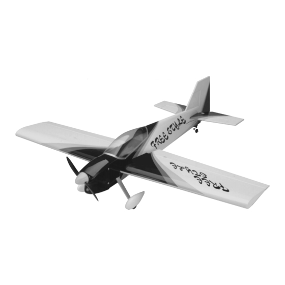
- Page 3 The Global Freestyle ARF changes all of this. Look closely at the Freestyle ARF and you will notice that it is built extremely light, yet is very strong. The fuselage is built up from lightweight balsa and plywood and the tail surfaces are built-up balsa.
- Page 4 The following section describes our recommendations to help you in deciding which types of accessories to purchase for your new Global Freestyle ARF. First, decide on the type of flying you want to do, then look at which items you'll need.
- Page 5 ADDITIONAL ITEMS REQUIRED The items listed below are required in addition to the items recommended in the previous section. Those items will vary depending upon the setup you choose - either the sport flying setup or the 3D aerobatics setup. Dubro 1/4"...
- Page 6 KIT CONTENTS We have organized the parts as they come out of the box for easier identification during assembly. Before you begin assembly, group the parts like we list them below. This will ensure that you have all of the parts before you begin assembly and it will also help you become familiar with each part.
- Page 7 {1} Decal Set REPLACEMENT PARTS Global carries a complete line of replacement parts for the Freestyle ARF. Listed below are the replacement parts that are available along with their respective part numbers for easy ordering convenience. These replacement parts can...
- Page 8 A NOTE ABOUT COVERING The covering material used on the Freestyle ARF is real iron-on heat shrink covering material, not cheap "shelf paper." Because of this, it is possible with heat and humidity changes that the covering on your airplane may wrinkle or sag. This trait is inherent in all types of heat shrink material.
- Page 9 should slide into each wing half up to the centerline you 9) Slide the dihedral brace into the wing half up to drew. If it does not, remove the dihedral brace and use its centerline. Remove any excess epoxy before it dries, 220 grit sandpaper with a sanding block to lightly sand using a paper towel and rubbing alcohol.
- Page 10 MOUNTING THE WING 2) Using a ruler and a pencil, carefully draw a vertical centerline on one side of the 25mm x 55mm 8) Place the wing into the wing saddle and secure it plywood plate. See photo # 5 below. into place using two 4mm x 40mm socket head screws Photo # 5 and two 4mm flat washers.
- Page 11 INSTALLING THE BELLY PAN 3) With the wing installed on the fuselage, set the belly pan into place and push it down firmly. Align both 7) Mix a small quantity of Kwik Bond 30 Minute the front and back of the belly pan with the sides and bot- Epoxy.
- Page 12 each tip of the stabilizer, both measurements will be the F) With the stabilizer held firmly in place, look from the front of the airplane at both the wing and the same when the stabilizer is centered. See figure # 1 below. stabilizer.
- Page 13 before the epoxy sets up. Wipe away any excess epoxy 3) Remove the stabilizer and hold it up to a bright using a paper towel and rubbing alcohol, and hold the light. Look carefully at the stabilizer and you will see the stabilizer in place using several pieces of masking tape.
- Page 14 Ernst Airplane Stand Paper Towels Because of the large size of the control surfaces on the Freestyle ARF it is absolutely imperative that the hinges be glued properly. This includes both having a tight hinge gap and using plenty of C/A glue.
- Page 15 20) Slide the rudder and its hinges into the hinge If any C/A gets onto the elevator halves, it can be removed promptly using a paper towel soaked with a small slots in the trailing edge of the stabilizer and the fuselage. Adjust the rudder so that there is no more than a 1/16"...
- Page 16 ASSEMBLING THE BRACKET 6) Using a Dremel Tool with a cutting disc attach- ment, carefully cut off the top of the tail wheel wire flush 1) Push one of the brass collets into the top and one with the top of the tiller arm. into the bottom of the nylon tail wheel bracket.
- Page 17 MAIN LANDING GEAR 13) Rotate the tiller arm out of the way. Using a drill with a 5/64" drill bit, drill a 3/4" deep hole into the ITEMS REQUIRED bottom of the rudder at the mark you drew. {1} Aluminum Main Gear Strut Make sure you drill the hole 90º...
- Page 18 3) When satisfied with the alignment, secure the 10) Using a Dremel Tool with a cutting disc attach- strut into place using two 4mm x 20mm machine screws. ment, carefully cut a slot from the hole you drilled down Tighten the screws firmly using a # 1 phillips screwdriver. to the bottom of the wheel pant.
- Page 19 15) While holding the hex nut inside the wheel pant 1) Install the two nylon engine mount beams, along with needle nose pliers, tighten the outer hex nut firmly with the plywood thrust plate, using four 4mm x 30mm using an adjustable wrench. socket head screws and four 4mm large O.D.
- Page 20 SERVO INSTALLATION 4) While holding the engine firmly in place, use a pencil to mark the four engine mounting screw locations TOOLS AND SUPPLIES REQUIRED onto the engine mounting beams. See photo # 32 below. # 1 Phillips Head Screwdriver Photo # 32 Excel Modeling Knife Electric Drill...
- Page 21 5) Using a # 1 phillips screwdriver, install and 11) Repeat steps # 7 through # 10 to install the tighten the mounting screws to hold the servos in place. second aileron servo in the other half of the wing. See photo # 35 below.
- Page 22 Roughening the smooth plastic will help the C/A 11) Using a drill with a 5/64" drill bit, enlarge the adhere to it better. third hole out from the center of the servo arm. 5) Slide the plastic tube through the hole you drilled 12) Install one adjustable servo connector through in the firewall.
- Page 23 ELEVATOR CONTROL SYSTEM Before gluing the plastic tube into place in the next step, use 220 grit sandpaper to roughen only the gluing ITEMS REQUIRED surface of the tube. {1} Hardwood Split Elevator Pushrod 17) Using Kwik Bond Thick C/A, glue the plastic {2} Nylon Control Horns tube to the side of the fuselage.
- Page 24 4) Remove the control horn and set it aside. Using 11) Thread one nylon clevis onto the threaded end a drill with a 5/64" drill bit, carefully drill two holes of each pushrod wire. For security, thread the clevises on through the elevator at the marks you drew.
- Page 25 24) If the elevator halves are moving more than 18) Slide the adjustable servo connector/servo horn 1-3/8", move the adjustable connector in one hole toward assembly over the plain end of the pushrod wire. Attach the center of the servo horn to decrease the control de- the servo horn to the servo output shaft, making sure that flection.
- Page 26 2) Using a drill with a 9/64" drill bit, drill a hole 10) Working with one length of cable for now, slide through the rudder where the two marks intersect. one brass collet, non-flange side first, over one end of the cable.
- Page 27 18) Using a drill with a 5/64" drill bit, enlarge the 26) Carefully apply a couple of drops of Kwik Bond Thin C/A to the brass collet. third hole out from the center of each servo arm. The C/A will "wick" between the collet and the cable, 19) Using a modeling knife and a ruler, measure and making the joint even stronger.
- Page 28 33) If the control surface deflection is more or less 4) Remove the control horn and set it aside. Using than 2-3/8" it must be changed. If your radio is equipped a drill with a 5/64" drill bit, carefully drill two holes with End Point Adjustments (EPA), make those adjust- through the aileron at the marks you drew.
- Page 29 13) Install the Z-Bend in the end of one pushrod 18) Repeat steps # 10 through # 17 to install the wire into the hole that you enlarged in the servo arm. In- second aileron pushrod. stall the wire so that the long portion of the wire comes ADJUSTING THE PUSHRODS out on the top of the servo arm.
- Page 30 FUEL TANK 4) Using a modeling knife, cut away and remove part of the second nylon vent tube, leaving 1/4" beyond ITEMS REQUIRED the bend. This will be the fill tube. {1} 280cc Fuel Tank You have to cut the fill tube shorter so that the stop- {1} Nylon Fuel Tank Cap per assembly will fit into the fuel tank opening.
- Page 31 9) Check to make sure that the weighted fuel pick-up Make sure that the fuel tank is right-side up. The top of the fuel tank should be toward the top of the fuselage. moves freely within the tank. The end of the fuel pick-up should be about 3/8"...
- Page 32 If any part of the template is touching the engine, re- 2) Remove the tape from the clear molded cowling template so that you have a right and left half. move the template and adjust the sizes of the cutouts until you are satisfied with the fit.
- Page 33 INSTALLING THE If you are using a four stroke engine you may need to PROPELLER AND THE SPINNER cut away and remove some of the template to clear the muffler's exhaust header. 25) Slide the spinner backplate onto the engine's crankshaft, followed by the propeller and the propeller 17) Using a drill with a 3/8"...
- Page 34 FINAL ASSEMBLY 3) Using a ruler and a pencil, measure back 1-5/8" from the back edge of the cockpit cutout, at the top of the ITEMS REQUIRED fuselage, and draw a mark. {2} Nylon Molded Wing Skids 4) Set the canopy on the fuselage, aligning the back edge of the canopy with the mark you drew.
- Page 35 13) Using a modeling knife, cut out two pieces of Dubro 1/4" foam rubber large enough to be wrapped BALANCING THE FREESTYLE ARF around the receiver and the battery pack. 1) It is critical that your airplane be balanced cor- 14) Wrap the receiver and the battery pack in the rectly.
- Page 36 This location is recommended for initial test flying. The C.G. can be moved fore or aft up to 1/2", but it is not 1) We recommend setting up the Freestyle using the recommended that the C.G. be located any farther back control throws we recommended in the pushrod installa- than 4-1/4"...
- Page 37 You should not deliberately fly your model in a reckless and/or danger- In the air the Freestyle is as smooth and docile or as ous manner. wild and aerobatic as you want it to be. What's to say: It's made for aerobatics and that's what it does best.
- Page 38 3D AEROBATIC FLYING SETUP When setting up an airplane for 3D flying, there are some points that you should be aware of. If you're a veteran of high performance aerobatics, you've probably heard this information before but, if this is your first high performance 3D airplane, this information will be very important to you.
- Page 39 RADIO SETUP FOR 3D FLYING Although you don't have to use a computer radio to enjoy the flying qualities of the Freestyle, if you're planning on doing 3D aerobatics it is recommended. Before making any adjustments, please read and understand your radio's setup manual.
- Page 40 TRIM CHART After you have test flown and done the initial trim changes to the aircraft, use the Trim Chart below to begin trimming your airplane. Following and adhering to this chart will result in the ability to diagnose trim problems and correct those problems using the simple adjustments shown below.
- Page 43 Do not use staples and make sure our address faces out. 1) Kit: Global Freestyle ARF 7) Was any of the assembly difficult for you? If yes, please explain.
- Page 44 _____________________________ Post Office will _____________________________ not deliver _____________________________ without proper postage (Return Address Here) Global Hobby Distributors Attn: Customer Care 18480 Bandilier Circle Fountain Valley CA 92728-8610 Fold along dotted line...
Need help?
Do you have a question about the Freestyle and is the answer not in the manual?
Questions and answers