Table of Contents
Advertisement
E2013 Lennox Industries Inc.
Dallas, Texas, USA
THIS MANUAL MUST BE LEFT WITH THE
HOMEOWNER FOR FUTURE REFERENCE
General
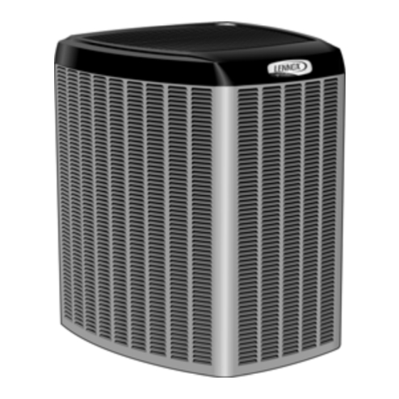
This XC25 outdoor unit is designed for use with HFC-410A
refrigerant only.
These instructions are intended as a general guide and do
not supersede local codes in any way. Consult authorities
having jurisdiction before installation.
IMPORTANT: BEFORE APPLYING ANY POWER (MAIN, SOLAR
OR LOW VOLTAGE) TO THE OUTDOOR UNIT, THE FIELD MUST
CONFIRM ICOMFORT WI-FI
OR HIGHER SOFTWARE. (REFERENCE ICOMFORT WI-FI
)
THERMOSTAT MANUAL
THIS UNIT IS A INTEGRAL COMPONENT OF A SYSTEM THAT
WILL REQUIRE AN ICOMFORT WI-FI
ICOMFORT™ -ENABLED AIR HANDLER OR FURNACE.
iComfort™-enabled
XC25
STEP 1 -- SETTING THE UNIT -- Clearances
CLEARANCE ON ALL SIDES — INCHES (MILLIMETERS)
6 (152)
12 (305)
36 (914)
MINIMUM CLEARANCE BETWEEN TWO UNITS
6/14/2013
*2P6142013*
®
THERMOSTAT HAS VERSION 2.1
®
THERMOSTAT AND
®
iComfort WI-FI
air handler or
furnace
NOTES:
S Clearance to access panel must be 30
CONTROL
PANEL ACCESS
S Clearance to one of the other three
LOCATION
30 (762)
S Clearance to one of the remaining two
Note: Dimensions are not to scale.
24
(610)
INSTALLATION
INSTRUCTIONS
Dave Lennox Signature
Collection XC25 System
AIR CONDITIONERS
507004-01
6/14/2013
Supersedes 6/2013
®
OUTDOOR UNIT
Improper installation, adjustment, alteration, service or
maintenance can cause property damage, personal inju
ry or loss of life.
Installation and service must be performed by a licensed
HVAC professional installer (or equivalent) or service
agency.
inches (762mm).
sides must be 36 inches (914mm).
sides may be 12 inches (305mm) and
the final side may be 6 inches
(152mm).
CONNECTIONS
FIGURE 1
Page 1
PACKING LIST
GROMMETS (2) BUSHING (1)
WARRANTY
CARD
WARNING
MINIMUM CLEARANCE
ABOVE UNIT
48 (1219)
ACCESS
PANEL
LINE SET
REAR VIEW OF UNIT
507004-01
*P507004-01*
®
Litho U.S.A.
RAST 6-PIN
CONNECTOR (1)
Advertisement
Table of Contents

Subscribe to Our Youtube Channel
Related Manuals for Lennox XC25 Series


Summary of Contents for Lennox XC25 Series
-
Page 1: Installation Instructions
INSTALLATION INSTRUCTIONS E2013 Lennox Industries Inc. Dallas, Texas, USA Dave Lennox Signature ® THIS MANUAL MUST BE LEFT WITH THE HOMEOWNER FOR FUTURE REFERENCE Collection XC25 System General AIR CONDITIONERS This XC25 outdoor unit is designed for use with HFC-410A... - Page 2 DETAIL A DETAIL B INSTALL UNIT AWAY FROM WINDOWS INSTALL UNIT LEVEL OR, IF ON A SLOPE, MAINTAIN SLOPE TOLERANCE OF 2 DEGREES (OR 2 INCHES PER 5 FEET [50 MM PER 1.5 M]) AWAY FROM BUILDING STRUCTURE. BUILDING STRUCTURE MOUNTING SLAB TWO 90°...
- Page 3 Take low doses, which may cause serious illness or death. It care while handling this equipment. may also cause cancer, birth defects, or reproductive harm. Page 3 XC25 SERIES...
- Page 4 Take care to empty all existing traps. Polyol es IMPORTANT ! ter (POE) oils are used in Lennox units charged with HFC-410A refrigerant. Residual mineral oil can act If unit is equipped with a crankcase heater, and outdoor as an insulator, preventing proper heat transfer.
- Page 5 5. Select or consider the larger liquid line size shown in the table if the elevation does not meet your requirements. NOTE - For new or replacement line set installation, refer to Service and Application Note - Corp. 9112-L4 (C-91-4). Page 5 XC25 SERIES...
- Page 6 STEP 2 -- REFRIGERANT PIPING -- Removing Existing Indoor Metering Device TYPICAL EXISTING FIXED ORIFICE TYPICAL EXISTING EXPANSION VALVE REMOVAL REMOVAL PROCEDURE PROCEDURE (UNCASED COIL SHOWN) (UNCASED COIL SHOWN) STUB END TWO-PIECE PATCH PLATE LIQUID LINE DISTRIBUTOR TUBES (UNCASED COIL ONLY) ORIFICE EXPANSION LIQUID LINE ORIFICE HOUSING...
- Page 7 OPEN AND SERVICE PORT CORE REMOVED SUCTION / TO ALLOW EXIT POINT FOR NITROGEN FLOW VAPOR LINE SERVICE VALVE SUCTION / VAPOR LINE OUTDOOR INDOOR UNIT UNIT NITROGEN LIQUID LINE SERVICE LIQUID LINE VALVE FIGURE 4 Page 7 XC25 SERIES...
- Page 8 CAUTION WARNING Brazing alloys and flux contain materials which are Danger of fire. Bleeding the refrigerant hazardous to your health. charge from only the high side may result Avoid breathing vapors or fumes from brazing in pressurization of the low side shell and operations.
- Page 9 EITHER THE 4 OR 8 O'CLOCK SEAL BONNET POSITION. NEVER MOUNT SENSING BULB BOTTOM OF LINE. MALE BRASS EQUALIZER LINE FITTING BULB BULB VAPOR LINE NOTE — NEVER MOUNT THE SENSING BULB ON BOTTOM OF LINE. FIGURE 6 Page 9 XC25 SERIES...
- Page 10 STEP 4 -- LEAK TEST AND EVACUATION HIGH MANIFOLD GAUGE SET OUTDOOR UNIT TO VAPOR SERVICE VALVE NOTE - Position canister to deliver liquid refrigerant. NITROGEN HFC-410A CONNECT GAUGE SET A. Connect the high pressure hose of an HFC-410A manifold gauge set to the vapor valve service port. NOTE —...
- Page 11 Reinstall service valve cores by removing manifold hose from service valve. Quickly install cores with core tool while maintaining a positive system pressure. Replace stem caps and finger tighten them, then tighten an additional one-sixth (1/6) of a turn as illustrated. FIGURE 8 Page 11 XC25 SERIES...
- Page 12 STEP 5 -- ELECTRICAL -- Circuit Sizing and Wire Routing In the U.S.A., wiring must conform with current local codes CAUTION and the current National Electric Code (NEC). In Canada, wiring must conform with current local codes and the cur rent Canadian Electrical Code (CEC).
- Page 13 PUMP DOWN - WHEN UNIT IS IN PUMP DOWN MODE, Pd WILL BE DISPLAYED ON 7-SEGMENT. TO ACTIVATE PUMP DOWN MODE, THE CONTROL MUST BE IN THE IDLE STATE, AND THE PUMP DOWN JUMPER PLACED ACROSS THE TWO PUMP DOWN PINS. TO DEACTIVATE, REMOVE JUMPER. FIGURE 10 Page 13 XC25 SERIES...
- Page 14 ROUTE CONTROL WIRES ELECTRICAL (CONTROL WIRING) AND LINE SET INLETS USE Maximum length of wiring (18 gauge) for all connections on TYPICAL CONTROL BOX BUSHING AND GROMMETS the RSBus is 1500 feet (457 meters). Wires should be color- PROVIDED IN BAG º...
- Page 15 XC25 Installation and Ser 1. Ask your Lennox dealer to show you where your indoor vice Procedures Corp. 1253-L11. unit's filter is located. It will be either at the indoor unit...
- Page 16 XC25 Start-Up and Performance Checklist Customer Address Indoor Unit Model Serial Outdoor Unit Model Serial Solar Module Mfg and Model Serial Notes: START-UP CHECKS Refrigerant Type: Rated Load Amps Actual Amps Rated Volts Actual Volts Condenser Fan Full Load Amps Actual Amps: COOLING MODE Vapor Pressure:...
Need help?
Do you have a question about the XC25 Series and is the answer not in the manual?
Questions and answers