Table of Contents
Advertisement
Service Literature
NOTICE
A thermostat is not included and must be ordered
separately.
D The Lennox
icomfort Toucht thermostat
in communicating applications.
D In
non−communicating
®
ComfortSense
7000 thermostat may be used, as well
as other non−communicating thermostats.
In all cases, setup is critical to ensure proper system
operation.
Field
wiring
examples
applications begin on page 22.
See the icomfort Toucht thermostat Quick Start Guide
for communicating and partial communicating field wiring
connections.
WARNING
Improper installation, adjustment, alteration, service or
maintenance can cause personal injury, loss of life, or
damage to property.
Installation and service must be performed by a licensed
professional installer (or equivalent) or a service agency.
Accessories
For update−to−date information, see any of the following
publications:
S Lennox XC17 Engineering Handbook
S Lennox Product Catalog
S Lennox Price Book
Corp. 1022−L3
Revised August 2, 2010
XC17 (HFC−410A) SERIES UNITS
must be used
applications,
the
Lennox
for
non−communicating
Page 1
TABLE OF CONTENTS
. . . . . . . . . . . . . . . . . . . . . . . . . . . . . . . . .
. . . . . . . . . . . . . . . . . . . . . . . . . . . . . . . .
. . . . . . . . . . . . . . . . . . . . . . . . . . . . . .
. . . . . . . . . . . . . . . . . . . . . . . . . . . . . . .
. . . . . . . . . . . . . . . . . . . . . . . . . . .
. . . . . . . . . . . . . . . . . . . . . . . . .
. . . . . . . . . . . . . . . . . . . . . . . . . . . . . . . . . . . . .
. . . . . . . . . . . . . . . . . . . . . . . . . . .
. . . . . . . . . . . . . . . . . . . . . . . . . . . . . . . .
. . . . . . . . . . . . . . . . . . . . . . . . . . . . . . . . . .
. . . . . . . . . . . . . . . . . . . . . . . . . . .
. . . . . . . . . . . . . . . . . . . . . . . . . . . .
. . . . . . . . . . . . . . . . . . . . . . . . . . . . . . .
. . . . . . . . . . . . . . . . . . . . . . . . . .
®
. . . . . . . . . . . . . . . . . . . . . . . . . .
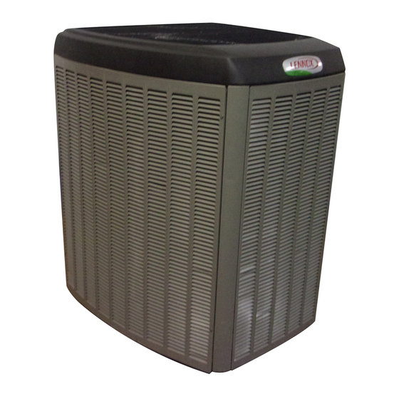
The XC17 is a high efficiency residential split−system air
conditioner unit, which features a one−stage scroll
compressor, icomfortt control and HFC−410A refrigerant.
Units are available in 2, 3, 4 and 5−ton sizes. This model
series is designed for use with an expansion valve
metering device only. Refer to the XC17 Engineering
Handbook for ordering the correct indoor coil expansion
valve.
This model is also SunSourcet ready beginning with
XC17−XXX−230−02 build.
. . . . . . . . . . . . . . . . . . . .
. . . . . . . . . . . . . .
. . . . . . . . . . . . . . . . .
. . . . . . . . .
. . . . . . . . . . . . . . . . .
. . . . . . . . . . . . . . . . . .
. . . . . . . . . . . . . . . . . . . . . . .
. . . . . . . . . .
. . . .
. . . . . . . . . . . . . .
. . . . . . . . . . . . .
. . . . . . . . . . . . . . . . . . .
2010 Lennox Industries Inc.
2
2
2
3
4
5
6
8
11
12
15
17
19
20
22
24
27
27
31
32
36
41
48
49
50
51
56
Advertisement
Table of Contents

Related Manuals for Lennox XC17 Series


Summary of Contents for Lennox XC17 Series
-
Page 1: Table Of Contents
For update−to−date information, see any of the following metering device only. Refer to the XC17 Engineering publications: Handbook for ordering the correct indoor coil expansion S Lennox XC17 Engineering Handbook valve. S Lennox Product Catalog This model is also SunSourcet ready beginning with S Lennox Price Book XC17−XXX−230−02 build. -
Page 2: Specifications
Model Number Identification C 17 036 − − −3 Refrigerant Type Minor Revision Number X = R−410A Voltage 230 = 208/230V−1ph−60hz Unit Type C = Air Conditioner Nominal Cooling Capacity 024 = 2 tons 030 = 2.5 tons Series 036 = 3 tons 042 = 3.5 tons 048 = 4 tons 060 = 5 tons... -
Page 3: Electrical Data
Unit Outdoor Fan Model Number Sound Rating Number Factory Refrigerant Number of Blades Diameter − inches. (dB) Charge XC17−060−230−01 13 lbs. 4 oz. 26.2 XC17−060−230−02 13 lbs. 4 oz. 26.2 XC17−060−230−03 12 lbs. 14 oz. 26.2 Tested according to AHRI Standard 270−2008 test conditions. Refrigerant charge sufficient for 15 feet length of refrigerant lines. -
Page 4: Unit Dimensions
208/230V−60 Hz−1 Ph Unit Compressor Condenser Fan Maximum Over− Minimum Locked Model Number Rated Load Full Load current Protection Circuity Rotor Amps Motor HP Nominal RPM Amps (RLA) Amps (FLA) (amps) Ampacity (LRA) XC17−060−230−01 35.0 26.4 134.0 XC17−060−230−02 35.0 26.4 134.0 XC17−060−230−03 33.3... -
Page 5: Typical Unit Parts Arrangement
Typical Unit Parts Arrangement SECOND GROUND LUG FOR SOURCESOURCEt FAN MOTOR CONTROL (A177) GROUND LUG CONTACTOR−1POLE (K1−1) WIRE TIE HIGH VOLTAGE FIELD CONNECTIONS SLEEVE OUTDOOR AMBIENT TEMPERATURE SENSOR (RT13) CAPACITOR (C12) CONTROL BOX AIR CONDITIONER CONTROL (A175) EXTERNAL SURGE PROTECTION USED ON XC17−XXX−230−01 AND −02 ONLY). -
Page 6: Operating Gauge Set And Service Valves
This unit must be matched with an indoor coil as See the Lennox Service and Application Notes #C−08−1 specified in Lennox’ Engineering Handbook. Coils for further details and information. previously charged with HCFC−22 must be flushed. -
Page 7: Service Valves
SERVICE VALVES ANGLE AND BALL Operating Angle Type Service Valve: 1. Remove stem cap with an appropriately sized wrench. 2. Use a service wrench with a hex−head extension (3/16" for liquid line valve sizes and 5/16" for vapor line valve sizes) to back the stem out counterclockwise as far as it will go. -
Page 8: Unit Placement
MINIMUM CLEARANCE CLEARANCE ON ALL SIDES INCHES (MILLIMETERS) ABOVE UNIT 6 (152) ACCESS PANEL NOTES: CONTROL PANEL 1. CLEARANCE 48 (1219) ACCESS OTHER THREE SIDES MUST BE 36 LOCATION 30 (762) INCHES (914MM). 12 (305) 2. CLEARANCE REMAINING TWO SIDES MAY BE 12 INCHES (305MM) AND THE FINAL SIDE MAY BE 6 INCHES (152MM). - Page 9 STABILIZING UNIT ON UNEVEN SURFACES ROOF MOUNTING IMPORTANT Install the unit a minimum of 6 inches (152 mm) above the roof surface to avoid ice build−up around the unit. Locate the unit above a load bearing wall or area of the roof that Unit Stabilizer Bracket Use (field−provided): can adequately support the unit.
- Page 10 DETAIL D DETAIL C Slab Side Mounting #10 1/2" LONG SELF−DRILLING SHEET METAL SCREWS COIL STABILIZING BRACKET (18 GAUGE METAL 2" WIDTH; HEIGHT AS BASE PAN REQUIRED) #10 1−1/4" LONG HEX HD SCREW AND FLAT WASHER CORNER POST BASE CONCRETE SLAB PLASTIC ANCHORS (HOLE DRILL 1/4")
-
Page 11: Removing And Installing Panels
Removing and Installing Panels ACCESS PANEL REMOVAL PANELS Removal and reinstallation of the access panel is as illustrated. ACCESS AND LOUVERED REMOVE 4 SCREWS TO WARNING REMOVE PANEL FOR ACCESSING COMPRESSOR To prevent personal injury, or damage to panels, unit or structure, be sure to ob- AND CONTROLS. -
Page 12: New Or Replacement Line Set
This section provides information on installation or replacement of existing line set. If new or replacement line To obtain the correct information from Lennox, be sure to set is not being installed then proceed to Brazing communicate the following information: Connections on page 14. - Page 13 LINE SET IMPORTANT Refrigerant lines must not contact structure. INSTALLATION REFRIGERANT LINE SET INSTALLING Line Set Isolation The following illustrations are VERTICAL RUNS (NEW CONSTRUCTION SHOWN) examples of proper refrigerant line set isolation: NOTE Insulate liquid line when it is routed through areas where the surrounding ambient temperature could become higher than the REFRIGERANT LINE SET TRANSITION...
- Page 14 BRAZING NOTE − Use silver alloy brazing rods with five or six percent minimum silver alloy for copper−to−copper brazing, 45 percent alloy for copper−to−brass and copper−to−steel brazing. CONNECTIONS CAP AND CORE REMOVAL Remove service cap and core CUT AND DEBUR from both the vapor and liquid line Cut ends of the refrigerant lines square service ports.
-
Page 15: Flushing The System
Flushing the System FLUSHING TYPICAL CHECK EXPANSION VALVE REMOVAL PROCEDURE (Uncased Coil Shown) STUB END LINE SET AND INDOOR COIL (1 OF 2) TWO PIECE PATCH PLATE LIQUID LINE CHECK (UNCASED COIL ONLY) ORIFICE EXPANSION TYPICAL FIXED ORIFICE REMOVAL PROCE- HOUSING VALVE DISTRIBUTOR... - Page 16 FLUSHING LINE SET AND INDOOR COIL (2 OF 2) TYPICAL CHECK EXPANSION VALVE INSTALLATION PROCEDURE This outdoor unit is designed for use in systems that use check expansion valve metering device. See the Lennox XC17 Engineering Hand- book for approved check expansion valve kit match−ups and application information.
-
Page 17: Leak Testing The System
Polyol ester (POE) oils are death. used in Lennox units charged with HFC−410A Never use oxygen to pressurize or refrigerant. Residual mineral oil can act as an insulator, purge refrigeration lines. Oxygen, preventing proper heat transfer. -
Page 18: Leak Test
LEAK TEST LINE SET AND INDOOR COIL NOTE Normally, the high pressure hose is connected to the liquid line port. However, connecting it to the vapor port better protects the manifold gauge set from high pressure damage. CONNECT GAUGE Connect an HFC−410A manifold gauge set high pressure hose to the vapor valve service port. -
Page 19: Evacuating The System
Evacuating the System EVACUATING MANIFOLD LINE SET AND INDOOR COIL GAUGE SET CONNECT GAUGE HIGH NOTE Remove cores from service valves (if not al- ready done). Connect low side of manifold gauge set with 1/4 SAE in−line tee to vapor line service valve A34000 1/4 SAE TEE WITH Connect high side of manifold gauge... -
Page 20: Electrical
defined as any gas that will not condense under IMPORTANT temperatures and pressures present during operation of an air conditioning system. Non−condensables and water Use a thermocouple or thermistor electronic vacuum suction combine with refrigerant to produce substances gauge that is calibrated in microns. Use an instrument that corrode copper piping and compressor parts. - Page 21 ROUTE CONTROL WIRES NON−COMMUNICATING Install low voltage control wiring from outdoor to indoor unit and from CONTROL BOX thermostat to indoor unit as illustrated. See figures 8 and 9 for typical configurations. Run 24VAC control wires through hole with grommet. Make 24VAC control wire connections to air conditioner control (A175).
-
Page 22: Field Control Wiring
Field Control Wiring ComfortSense[ 7000 Thermostats One−Stage Air Handler Control Catalog # Y0349 or Y2081 Air Conditioner Control On−board link Low voltage thermostat wiring Flat metal jumper i− 1. Thermostat T terminals are used for outdoor sensor input. Use for thermostat’s outdoor temperature display (optional). ®... - Page 23 ComfortSense[ 7000 Thermostats One−Stage Furnace Control Catalog # Y0349 or Y2081 Air Conditioner Control On−board link Low voltage thermostat wiring i− Cut on−board link (W914) (clippable wire) from DS to R for dehumidification (Optional). 1. Thermostat T terminals are used for outdoor sensor input. Use for thermostat’s outdoor temperature display (optional). ®...
-
Page 24: Air Conditioner Control (A175) Jumpers And Terminals
Air Conditioner Control (A175) Jumpers and Terminals AIR CONDITIONER CONTROL ONE STAGE TABLE 3 PROVIDES ADDITIONAL INFORMATION CONCERNING JUMPERS, LOOP, AND CONNECTIONS FOR THE AIR CONDITIONER CONTROL. TEST PINS DS11 and DS14 LED ALERT CODES DS13 and DS15 LED ALERT CODES CUT FOR HUMIDITROL ENHANCED... - Page 25 AIR CONDITIONER CONTROL ONE STAGE TABLE 3 PROVIDES ADDITIONAL INFORMATION CONCERNING JUMPERS, LOOP, AND CONNECTIONS FOR THE AIR CONDITIONER CONTROL. TEST PINS DS11 and DS14 LED ALERT CODES DS13 and DS15 LED ALERT CODES DS12 COMMUNICATING STATUS INDICATOR CUT FOR HUMIDITROL APPLICATION (TWO−STAGE UNITS ONLY) Figure 11.
- Page 26 Table 3. Air Conditioner Control (A175) Jumpers and Terminals Board ID Label Description PSC Fan 240 VAC output connection for outdoor fan. PSC Fan 240 VAC input connection for outdoor fan. 24VAC output for defrost auxiliary heat output. Thermostat service light connection. 24VAC thermostat input/output for second stage operation of the unit.
-
Page 27: Unit Start−Up
nameplate. If not, do not start the equipment until you Unit Start−Up have consulted with the power company and the voltage condition has been corrected. IMPORTANT 6. Set the thermostat for a cooling demand. Turn on If unit is equipped with a crankcase heater, it should be power to the indoor indoor unit and close the outdoor energized 24 hours before unit start−up to prevent unit disconnect switch to start the unit. - Page 28 ADDING OR REMOVING REFRIGERANT This system uses HFC−410A refrigerant which operates at much higher pressures than HCFC−22. The pre−installed liquid line filter drier is approved for use with HFC−410A only. Do not replace it with components designed for use with HCFC−22. This unit is NOT approved for use with coils which use capillary tubes or fixed orifices as a refrigerant metering device.
- Page 29 WEIGH IN to initially charge a system when the outdoor unit is void of charge. To verify charge and add or APPROACH SUBCOOLING remove refrigerant use either methods. WHEN TO CHARGE? START: Determine the correct charge method: Warm weather best Can charge in colder weather CHARGE METHOD? Determine by: Outdoor ambient temperature...
- Page 30 APPROACH 1. Confirm proper airflow across coil using figure 13. 2. Compare unit pressures with table 4, Normal Operating Pressures. TEST AND CHARGE METHOD 3. Use APPROACH to correctly charge unit or to verify the charge is 65ºF (18.3ºC) and Above correct.
-
Page 31: Operating And Temperature Pressures
Operating and Temperature Pressures Minor variations in these pressures may be expected due to differences in installations. Significant differences could mean that the system is not properly charged or that a problem exists with some component in the system. Use this table to perform maintenance checks; it is not a procedure for charging the system. -
Page 32: System Operations
SENSOR HIGH DISCHARGE LINE TEMPERATURE System Operation (RT28) The high discharge line temperature sensor location is IMPORTANT illustrated on page 5. This sensor’s sequence of operations is provided in figure 35. Some scroll compressor have internal vacuum protector that will unload scrolls when suction pressure goes below High Discharge Line Sensor Open/Shorted Event Condition 20 psig. - Page 33 S Sensor detects an out−of−range outdoor ambient air Table 6. Sensor Temperature / Resistance Range temperature condition and will display LED alert code Resistance on the air conditioner control. Temperature values range Pins/Wire Range °F (°C) (ohms) Color Sensor S The sensor is operating normally when the ambient air temperature at the sensor is below or above the air RT13 Outdoor −40ºF to 140ºF...
- Page 34 Table 7. RT13 Ambient Sensor Temperature / Resistance Range Degrees Degrees Degrees Degrees Resistance Resistance Resistance Resistance Fahrenheit Fahrenheit Fahrenheit Fahrenheit 136.3 2680 56.8 16657 21.6 44154 −11.3 123152 133.1 2859 56.0 16973 21.0 44851 −11.9 125787 130.1 3040 55.3 17293 20.5 45560...
- Page 35 Table 8. RT28 High Discharge Sensor Temperature / Resistance Range Degrees Degrees Degrees Degrees Resistance Resistance Resistance Resistance Fahrenheit Fahrenheit Fahrenheit Fahrenheit 303.1 186.1 1052 136.8 2656 94.5 6613 298.1 185.0 1072 136.0 2698 93.6 6739 293.4 183.9 1093 135.2 2740 92.8 6869...
-
Page 36: System Status, Fault And Lockout Led Codes
System Status, Fault and Lockout LED IMPORTANT Codes DS15 and DS13 compressor LED fault and lockout LED codes are displayed via various LEDs located on the codes do not provide safety protection. The is a air conditioner control (A175). See page for locations of air monitoring function only and cannot control or shut down conditioner control LEDs. - Page 37 Air Conditioner icomfort icomfort icomfort Control LEDs Toucht Toucht Toucht Possible Possible Possible Condition Condition Condition Solution Solution Solution Thermostat Thermostat Thermostat Cause(s) Cause(s) Cause(s) DS11 DS11 DS14 Red DS14 Red Display Display Display Green Green 1 Fast Heating Low Flash then Not Applicable Capacity...
- Page 38 Air Conditioner icomfort icomfort icomfort Control LEDs Toucht Toucht Toucht Possible Possible Possible Condition Condition Condition Solution Solution Solution Thermostat Thermostat Thermostat Cause(s) Cause(s) Cause(s) DS11 DS11 DS14 Red DS14 Red Display Display Display Green Green Discharge Line SLOW Moderate Alert This code detects high discharge temperatures.
- Page 39 Air Conditioner icomfort icomfort Control LEDs Toucht Toucht Possible Possible Clearing Status Clearing Status Condition Condition Solution Solution Cause(s) Cause(s) Thermostat Thermostat DS15 DS13 Yellow Display Display Low refrigerant charge. Evaporator blower is not running. Check blower relay coil and contacts Check blower motor capacitor Check blower motor for failure or blockage...
- Page 40 Air Conditioner icomfort icomfort Control LEDs Toucht Toucht Possible Possible Clearing Status Clearing Status Condition Condition Solution Solution Cause(s) Cause(s) Thermostat Thermostat DS15 DS13 Yellow Display Display Outdoor unit power disconnect is open. Unit circuit breaker or fuse(s) is open. Unit contactor has failed to close.
-
Page 41: Component Field Configuration And Troubleshooting
Verifying Correct DC Output Voltage (J2) Component Field Configuration and Troubleshooting The following three methods can be used to determine whether the fan motor (B4) is operating at the correct RPMs based on unit size. FAN MOTOR (B4) TEST PROCEDURE A simple test can be used to test the fan motor operation. - Page 42 Table 12. Fan Motor Control Flash and Pause Durations Flash or Pause State Duration Flash Flash Three flashes per second Slow Flash One flash per second Short Pause Two seconds of OFF time. Long Pause Five seconds of OFF time. Table 13.
- Page 43 CFM Profile Pin Select FAN MOTOR CONTROL (A177) PULSE−WIDTH MODULATION (PWM) JUMPER JUMPER CONTROL BOX CONDITIONER CONTROL (A175) VERIFY DC VOLTAGE OUTPUT USING FAN PWM OUT AND COM TERMINALS. SEE TABLE 14 FOR OPTIMAL DC VOLTAGE BASED ON CFM PROFILE USED. FAN PWM OUT GREEN GREEN...
-
Page 44: Control Box
CONTROL BOX FAN MOTOR CONTROL (A177) PULSE−WIDTH MODULATION (PWM) INPUT VOLTAGES DURING DEMAND ECM/Y1 ONLY − 24VDC YELLOW WIRE CONDITIONER BLUE WIRE CONTROL (A175) BLACK WIRE ONE YELLOW WIRE FROM PS (E24) TERMINAL ON AIR CONDITIONER CONTROL. AND SECOND YELLOW WIRES ON EXT PWR/R (24VAC INPUT PIGGYBACK TERMINALS GOES TO S4 HIGH PRESSURE SWITCH. - Page 45 Fan Motor (B4) Test Procedure A simple test can be used to test the fan motor operation. A fully charged 9V battery will be required for this procedure. FAN MOTOR TEST THIS IS A TEST THAT WILL VERIFY THAT THE MOTOR DOES OPERATE. 1.
- Page 46 TOP GRILLE OR FAN MOTOR MOUNT ADJUSTMENT FOR FAN CLEARANCE Sometimes during shipping, either the fan motor mounting or top grille may become out of alignment. This may cause the fan motor blade to not clear the orifice ring. If this situation occurs, simply adjust either or both the fan motor mount or top grille positions to allow proper clearance.
- Page 47 SETTING UNIT NOMINAL CAPACITY CODE 1. Alert Code 34, Must Program Unit Capacity for In a icomfortt enabled system, if the icomfort Toucht Outdoor Unit. thermostat is displaying either of the following alert codes, 2. Alert Code 313, Indoor and Outdoor Unit Capacity then the outdoor unit normal capacity will need to be set using the procedures outlined in figure 26.
-
Page 48: Routine Maintenance
For update−to−date information, see any of the following including the outdoor coil. Consult your installing publications: contractor for proper intervals/procedures for your geographic area or service contract. S Lennox XC17 Engineering Handbook S Lennox Product Catalog Indoor Unit S Lennox Price Book 1. Clean or change filters. -
Page 49: Sunsource ® Home Energy System
The SolarSynct package consists of the following components: S Lennox ® Solar Subpanel installed in a Dave Lennox ® Signature Collection air conditioner or heat pump unit. S Solar modules (1 to 15 may be used to vary the amount of electricity generated). -
Page 50: Start−Up And Performance Checklist
Start−Up and Performance Checklist Customer Address Indoor Unit Model Serial Outdoor Unit Model Serial Notes: START UP CHECKS Refrigerant Type _________ Rated Load Amps __________ Actual Amps Rated Volts Actual Volts Condenser Fan Full Load Amps Actual Amps: COOLING MODE Suction Pressure: Liquid Pressure: Supply Air Temperature:... -
Page 51: Unit Wiring Diagrams
Unit Wiring Diagrams Service technician will need to visually inspect the unit being service to determine which wiring diagram is applicable. Quick verification can usually be made by comparing the wiring diagram located on the unit access panel to the following diagrams. Figure 27. - Page 52 Figure 28. Typical XC17 Wiring (Non−Communicating with Fan Motor Surge Protection) (XC17−XXX−230−01) Page 52 XC17...
- Page 53 Figure 29. Typical XC17 Wiring (Non−Communicating, No Surge Protection and A177 Fan Motor Control Wiring Change) (XC17−XXX−230−01) XC17 Page 53...
- Page 54 Figure 30. Typical XC17 Wiring (Communicating, Surge Protection and A177 Fan Motor Control Wiring Change) (XC17−XXX−230−02) Page 54 XC17...
- Page 55 Figure 31. Typical XC21 Wiring − No External Surge Protection (XC17−XXX−230−03) XC17 Page 55...
-
Page 56: Unit Sequence Of Operations
Unit Sequence of Operations The following figures illustrated the overall unit sequence of operations along with various pressure switches and temperature sensor operations. The figures also illustration the use of the compressor anti−short cycle function in relations to unit Status, Fault and Lockout LED Codes system operations interaction. On 24VAC power−up or air conditioner control (A175) reset, the air conditioner control shall perform the following tasks:... - Page 57 INITIAL TRIP COMPRESSOR PRESSURE SWITCH IS CLOSED Y1 DEMAND CONTACTOR SWITCH (S87) IGNORED FOR ENERGIZED 90 SECONDS PRESSURE SWITCH IS CLOSED OR OUTDOOR CLOSED OPEN AMBIENT TEMPERATURE IS 15ºF SWITCH (S87) OR BELOW COMPRESSOR CONTACTOR If 5−strike counter has four or less strikes when Y1 demand DE−ENERGIZED is terminated or satisfied, the strike counter will reset to zero.
- Page 58 HIGH COMPRESSOR PRESSURE Y1 DEMAND CLOSED CONTACTOR SWITCH (S4) ENERGIZED HIGH PRESSURE CLOSED OPEN SWITCH (S4) COMPRESSOR If 5−strike counter has four or less strikes when Y1 demand CONTACTOR is terminated or satisfied, the strike counter will reset to zero. DE−ENERGIZED In a icomfort Toucht thermostat enabled setup, the thermostat will terminate demand when the compressor...
- Page 59 If temperature is at or above 279ºF. DISCHARGE COMPRESSOR Y1 DEMAND CLOSED SENSOR CONTACTOR (RT28)* ENERGIZED HIGH PRESSURE CLOSED OPEN SWITCH (S4) COMPRESSOR If 5−strike counter has four or less strikes when Y1 demand CONTACTOR is terminated or satisfied, the strike counter will reset to zero. DE−ENERGIZED In a icomfort Toucht thermostat enabled setup, the thermostat will terminate demand when the compressor...
Need help?
Do you have a question about the XC17 Series and is the answer not in the manual?
Questions and answers