Sign In
Upload
Download
Table of Contents
Contents
Add to my manuals
Delete from my manuals
Share
URL of this page:
HTML Link:
Bookmark this page
Add
Manual will be automatically added to "My Manuals"
Print this page
×
Bookmark added
×
Added to my manuals
Manuals
Brands
LG Manuals
Refrigerator
GR-359
Service manual
LG GR-359 Service Manual
Hide thumbs
1
Table Of Contents
2
3
4
5
6
7
8
9
10
11
12
13
14
15
16
17
18
19
20
21
22
23
24
25
26
27
28
29
30
31
32
33
34
35
36
37
38
39
40
41
page
of
41
Go
/
41
Contents
Table of Contents
Troubleshooting
Bookmarks
Table of Contents
Table of Contents
Safety Precautions
Servicing Precautions
Specifications
Parts Identification
Replacement of Door Opening Type
Disassembly
Door
Door Switch
Fan and Fan Motor
Def' Control Asm
Lamp
Adjustment
Compressor
Ptc-Starter
Olp (over Load Protector)
Circuit Diagram
Troubleshooting
Compressor and Electric Components
Ptc and Olp
Another Electric Component
Service Diagnosis Chart
Refrigerating Cycle
Micom Function & Pcb Circuit Explanation
Exploded View
Replacement Parts List
Advertisement
Quick Links
1
Specifications
2
Parts Identification
3
Troubleshooting
4
Exploded View
5
Replacement Parts List
Download this manual
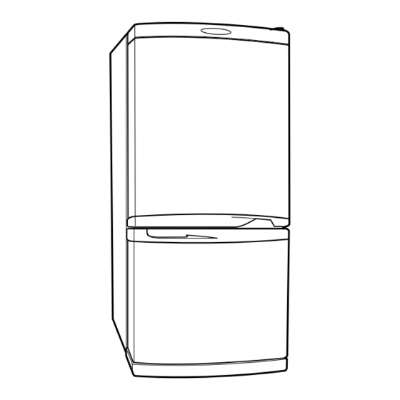
REFRIGERATOR
SERVICE MANUAL
CAUTION
BEFORE SERVICING THE UNIT, READ THE "SAFETY
PRECAUTIONS" IN THIS MANUAL.
MODEL: GR-359/399
Table of
Contents
Previous
Page
Next
Page
1
2
3
4
5
Advertisement
Table of Contents
Need help?
Do you have a question about the GR-359 and is the answer not in the manual?
Ask a question
Questions and answers
Related Manuals for LG GR-359
Refrigerator LG GR-382R Owner's Manual
Lg refrigerator freezer owner's manual (14 pages)
Refrigerator LG GR-382R Service Manual
(40 pages)
Refrigerator LG GR-389SNQF User Manual
(17 pages)
Refrigerator LG GR-349STQA.CTIQRAN Service Manual
Sxs refrigerator (36 pages)
Refrigerator LG GR-349SQF Service Manual
(41 pages)
Refrigerator LG LRBP1031W Service Manual
(36 pages)
Refrigerator LG GR-389 Service Manual
(37 pages)
Refrigerator LG GR-391SCA Service Manual
Refrigerator (38 pages)
Refrigerator LG GR-349R User Manual
Refrigerator-freezer (52 pages)
Refrigerator LG GR-349R User Manual
(17 pages)
Refrigerator LG gr-392 Service Manual
(18 pages)
Refrigerator LG GR-349SQF.CEWQEHU Service Manual
(36 pages)
Refrigerator LG Refrigerator Owner's Manual
(44 pages)
Refrigerator LG Refrigerator Owner's Manual
(16 pages)
Refrigerator LG GR-369 User Manual
(92 pages)
Refrigerator LG GR-349STQ Owner's Manual
(52 pages)
This manual is also suitable for:
Gr-399
Table of Contents
Save PDF
Print
Rename the bookmark
Delete bookmark?
Delete from my manuals?
Login
Sign In
OR
Sign in with Facebook
Sign in with Google
Upload manual
Upload from disk
Upload from URL


Need help?
Do you have a question about the GR-359 and is the answer not in the manual?
Questions and answers