
Related Manuals for LG gr-392


Summary of Contents for LG gr-392
- Page 1 CAUTION BEFORE SERVICING THE UNIT, READ THE "SAFETY PRECAUTIONS" IN THIS MANUAL. MODEL: GR-392...
-
Page 2: Table Of Contents
CONTENTS SAFETY PRECAUTIONS ............................... 2 SERVICING PRECAUTIONS..............................3 SPECIFICATIONS................................... 4 PARTS IDENTIFICATION ............................... 5 DISASSEMBLY..................................6-7 DOOR....................................6 DOOR SWITCH..................................6 THERMOSTAT ..................................6 FAN AND FAN MOTOR................................ 6 DEF' CONTROL ASM ................................7 LAMP....................................7 DAMPER CONTROL................................7 ADJUSTMENT..................................8-9 COMPRESSOR.................................. -
Page 3: Servicing Precautions
SERVICING PRECAUTIONS AIR RECHARGING IN COMPRESSOR vacuum operation is over, add the quantity in grams of R-12(R134a) to the refrigerant system. Remember that Test the refrigeration system connecting it electrically before every system has an exact quantity of R-12(R134a) with a refilling operation. -
Page 4: Specifications
1. SPECIFICATIONS 1-1. GR-392C/CV/S/SV ITEMS SPECIFICATIONS ITEMS SPECIFICATIONS FREEZER FREEZER 1 EA SHELF CAPACITY REFRIGERATOR REFRIGERATOR 2 EA (§⁄) TOTAL VEGETABLE TRAY Transparent Drawer Type DIMENSIONS (mm) 725(W) 632(D) 1684(H) EGG TRAY 2 EA NET WEIGHT (kg) ICE TRAY 2 EA COOLING SYSTEM Fan Cooling ICE BANK... -
Page 5: Parts Identification
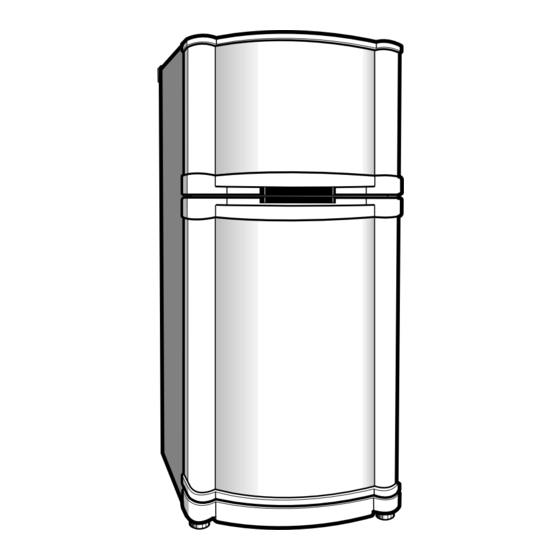
2. PARTS IDENTIFICATION FREEZER TEMP. QUICK FREEZING CONTROL KNOB CORNER ICE TRAY BASKET OF ICE BANK FREEZER REFRIGERATOR TEMP. CONTROL EGG TRAY KNOB MULTI DUCT-R SHELVES COVER VEGETABLE BOTTLE RACK TRAY VEGETABLE TRAY COVER LOWER ADJUSTABLE FEET NOTE : This is a basic model. The shape of refrigerator is subject to change. - 5 -... -
Page 6: Disassembly
3. DISASSEMBLY 3-1 DOOR 3-2 DOOR SWITCH 1. To remove the door switch, pull out it with a 'Ñ' type Freezer Door 1. Remove the hinge cover by pulling it upwards driver as shown in (Figure 9). 2. Loosen 3 hexagonal bolts fixing the upper hinge to the 2. -
Page 7: Def' Control Asm
2. Pull out the shroud assembly. 3-6 LAMP 3. Loosen 2 screws holding fan motor bracket to remove 3-6-1 Freezer the fan and fan motor assembly. 1. Remove all shelves in the freezer. 2. To remove the lamp cover, insert a 'Ñ' type driver in the lower gap and pull out it as shown in (Figure 15). -
Page 8: Adjustment
4. ADJUSTMENT 4-1 COMPRESSOR 4-2-3 PTC-Applied Circuit Diagram According to Starting Method of Motor 4-1-1 Role The compressor inhales low temp. and low pressure gas evaporated from Evaporator of the Refrigerator, and OVERLOAD PROTECTOR- condenses this gas to high temp. and high pressure gas, and then plays delivering role to Condenser. -
Page 9: Olp (Over Load Protector)
4-3. OLP (OVER LOAD PROTECTOR) CONTACTION- COVER- POINT- 4-3-1 Definition of OLP BIMETAL- 4. OLP (OVER LOAD PROTECTOR) is attached to CONTACTING- Hermetic Compressor and protects Motor by cutting off POINT- current in Compressor Motor by Bimetal in the OLP in HEATER- case of over-rising temperature. -
Page 10: Troubleshooting
6. TROUBLESHOOTING 6-1 COMPRESSOR AND ELECTRIC COMPONENTS YES- Remove the PTC- (Rating Voltage Power Source. Starter from the ±10%)? Compressor and measure the voltage between Terminal C of Compressor and Terminals 5 or 6 of PTC. YES- OLP disconnected? No Voltage. Replace OLP. -
Page 11: Ptc And Olp
6-2 PTC AND OLP Normal operation of Check another Separate the PTC- Observation value is Compressor is Starter from electric components. 220V/50Hz : 22§ ±30% Compressor and impossible or poor. 115V/60Hz : 6.8§ ±30% measure the 240V/50Hz : 33§ ±30% resistance between 127, 220V/60Hz : 22§... -
Page 12: Another Electric Component
6-4 ANOTHER ELECTRIC COMPONENTS Cooling is impossible Compressor Check if current flows to Cause doesn't run. the following components. Poor contacting and a. Thermostat gas leakage. b. Starting devices Shorted or broken. Poor contacting c. OLP or shorted. Coil shorted. d. -
Page 13: Service Diagnosis Chart
6-5 SERVICE DIAGNOSIS CHART COMPLAINT POINTS TO BE CHECKED REMEDY Cooling is ¥ Is the power cord unplugged from the outlet? ¥ Plug to the outlet. impossible. ¥ Check if the power S/W is setted to OFF. ¥ Set the switch to ON. ¥... -
Page 14: Refrigerating Cycle
6-6 REFRIGERATING CYCLE Troubleshooting Chart TEMPERATURE STATE OF STATE OF THE CAUSE REMARKS OF THE THE SET EVAPORATOR COMPRESSOR PARTIAL Freezer room and Low flowing sound of A little high ¥ A little Refrigerant LEAKAGE Refrigerator Refrigerant is heard and more than ¥... -
Page 15: Refrigerating Cycle
General Control of Refrigerating Cycle ITEMS CONTENTS AND SPECIFICATIONS REMARKS WELDING (1) H 30 ¥ Chemical Ingredients ¥ Recommend H34 containing 34% Ag in the (1) ¥ Ag: 30%, Cu: 27%, Zn: 23%, Cd: 20% ¥ Service Center. ¥ Brazing Temperature: 710~840¡C (2) Bcup-2 ¥... -
Page 16: Exploded View
7. EXPLODED VIEW The parts of refrigerator and the shape of each part are subject to change in different localities or model name. 281A 103B 281B 129A 105A 103A 110A 110B 411A 410G 410A 416A 110C 410H 282H 406B 125A 410F 410B 416B... - Page 17 401A 303B 200A 405C 404A 329A 301A 405C 405A 203A 202A 403A 201A 409B 330C 205A 418A 212G 205A 303A 332A 330B 128B 210B 131C 210A 131A 127A 149A 230A 235A 233A 232A 145A 231A 145B 205A 136A 136B 205A 149B 155A 241C...
-
Page 18: Replacement Parts List
P/NO. 3828JD8109D MAR., Printed in Korea 1998...
Need help?
Do you have a question about the gr-392 and is the answer not in the manual?
Questions and answers