Table of Contents
Advertisement
Advertisement
Table of Contents

Related Manuals for Fireray 5000


Summary of Contents for Fireray 5000
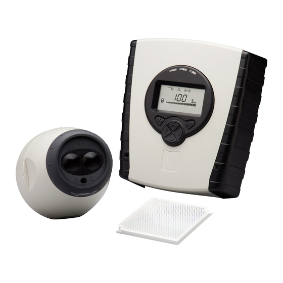
- Page 1 Motorised Infrared Optical Beam Smoke Detector User Guide...
- Page 2 1. General Information 50cm 50cm 50cm 50cm 8-100m 8-100m Mount on solid surfaces (structural wall or girder) Ensure clear line of sight from Detector to Reflector 50—100m = 4 18—50m = 1 8—18m = 1 Use Short Range Mask • All installations should comply with local regulations •...
- Page 3 2. Fitting the Product Clip PCB into base Insert Detector cable LED indicator must face downward...
- Page 4 3. Wiring Diagrams Wiring two Detectors onto two Zones: To Detector 1 To Detector 2 note 1 DET 1 DET 2 Con C Con D Fire Fault 14V - 36V DC Fire Fault Reset Con A Con B note 1 Zone 1 - Zone 1 + Ext Reset...
- Page 5 3. Wiring Diagrams (continued) Relay connections for wiring the two Detectors of one Controller onto one Zone: Con C Con D Fire Fault Fire Fault Con A Con B note 1 Zone 1 - Zone 1 + For wiring to other types of Fire Control Panel, or to wire multiple Controllers onto one Zone, refer to additional installation instructions supplied with the product...
- Page 6 4. Apply power NOTE: One System Controller can be used to control and monitor up to two Detector heads. The ‘#’ symbol in this guide is used to represent the number of the Detector currently selected (1 or 2). 5 seconds 5 seconds 5 seconds •...
- Page 7 5. Enter Pass Code to Access Engineering Menu Press for Pass Code screen: • Default Pass Code: 1 2 3 4 • Change digit • Move between digits • Accept • An incorrect Pass Code will return the display to the Pass Code entry screen •...
- Page 8 7. Select Power Mode • In ‘Hi A’ mode (default), during normal operation the system will take 5.5mA if one Detector is connected or 8mA if two Detectors are connected. During Laser targeting, Auto, Hand and Home functions, the system will take 36mA. •...
- Page 9 10. LASER Targeting The system will signal Fault while in this mode The LASER is used to align the Detector with the Reflector. It is an approximate alignment tool only. After Auto-Align the LASER will not necessarily be pointing on the Reflector •...
-
Page 10: System Is Aligned
12. ‘Set’ 0/100 (Calibrate) • When ‘Set’ is displayed press whilst the Reflector is still uncovered • When ‘S-00’ is displayed, cover the Reflector with a non- reflective material and leave covered, then press • When ‘S-01’ is displayed, uncover the Reflector and leave uncovered, then press •... -
Page 11: Remote Fire Test
14. Manual Fire and Fault Tests After installation or cleaning, it is recommended that a manual Fire and Fault test is performed: Fire Test: Cover the Reflector slowly so that it takes longer than 5 seconds to cover. The System Controller will signal Fire to the Fire Control Panel after the delay to fire has expired (10s default) Fault Test: Cover the Reflector completely within 2 seconds. - Page 12 16. Fire Threshold This setting is the threshold at which the Detector will detect a fire Default factory setting=35% (Set for each Detector) • Sensitivity can be adjusted in 1% steps by pressing up or down keys • Press to accept setting UL268 Fire Threshold Ranges: Distance between Fire Threshold...
- Page 13 17. Fire/Fault Delay These settings are the delays that the System Controller uses before signalling a FIRE or FAULT condition respectively to the Fire Control Panel. Default factory setting=10 seconds (Set for each Detector) Delay 1 (Fire) Delay 2 (Fault) 18.
- Page 14 19. Cleaning the System The system will automatically compensate for dust build-up by changing the Compensation Level. However, it is recommended that the Detector lenses and the Reflector are cleaned periodically with a soft lint-free cloth. If the Compensation Level for a particular Detector remains above 130 for several days, this indicates that cleaning should take place on that Detector.
- Page 15 20. Troubleshooting • Ensure clear line of sight • Refer to manufacturer for E-00 AIM not from Detector to Reflector for recognised technical assistance a radius of 0.5m Reflector Not • Ensure correct distance has Found during E-10 been selected •...
- Page 16 21. Technical Specifications Parameter Value Operating Voltage 14—36V DC Operating Current – Normal Operation 5.5mA - 1 Detector (including fire or fault activated) 8mA - 2 Detectors Operating Current – Alignment modes - HiA 36mA Alignment modes - LoA 5.5mA / 8mA 0.45—3.98 dB Fire Threshold Range 10—60%...
Need help?
Do you have a question about the 5000 and is the answer not in the manual?
Questions and answers