Advertisement
22318.26.01
www.acornfiresecurity.com
www.acornfiresecurity.com
FEATURES
•
Microprocessor
controlled
•
Range 5 – 50 Metres
•
Range 50 – 100 Metres
•
Unique simple alignment
•
Loop powered
•
Selectable alarm
thresholds
•
Low current
consumption
•
Automatic contamination
compensation
Loop Powered
Analogue Addressable
Advertisement
Table of Contents

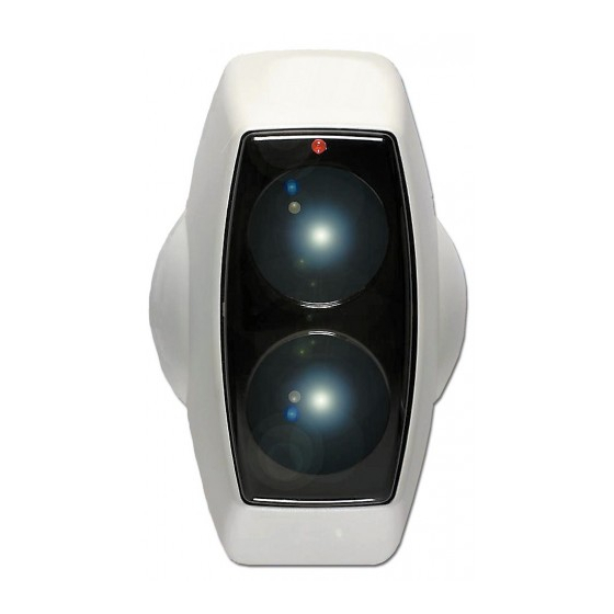
Summary of Contents for Fireray FD2705R
- Page 1 www.acornfiresecurity.com FEATURES • Microprocessor controlled • Range 5 – 50 Metres • Range 50 – 100 Metres • Unique simple alignment • Loop powered • Selectable alarm thresholds • Low current consumption • Automatic contamination compensation Loop Powered 22318.26.01 Analogue Addressable www.acornfiresecurity.com...
-
Page 2: System Description
Alarm and Fault as normal. 3. Detector Positioning. It is important that the Fireray FD2705R/FD2710R Detector is positioned correctly to minimise the detection time. Experiments have shown that smoke from a fire does not rise directly upwards, but fans out or mushrooms due to air currents and heat layering effects. - Page 3 9 metres either side of the beam, but only for the beam positioned in the apex. All other calculations remain the same. Limit to when a Fireray must be positioned in roof apex Angle of Pitch Limit...
-
Page 4: Installation
Due to the principle of the detector i.e. reflective, the prism(s) must NOT be mounted on glass or a polished reflective surface. Mount the Prism(s) on a solid structure, 90º to the beam path, between 5 to 50 metres (Fireray FD2705R), and 50 to100 metres (Fireray FD2710R) directly opposite the Detector. -
Page 5: Alignment Mode
www.acornfiresecurity.com 5. Prism Targeting Mode. Apply power to the Detector. There is a 5 seconds pre-charge delay after power is applied to allow the internal circuits to stabilise correctly. Do not remove the detector from the wall during this action. Using the mode switch (See fig. - Page 6 www.acornfiresecurity.com 6.3. Alignment Process Flow Diagram. After selecting alignment mode wait until both LED’s stop flashing Slowly adjust a thumbwheel in one direction and observe the LED’s Stop turning the Amber thumbwheel and flashing? wait for the Red LED to stop flashing.
-
Page 7: System Testing
www.acornfiresecurity.com 6.4. Exiting Alignment Mode. Do not remove the detector from the wall during this action. Using the mode switch (See fig. 4) select ‘Operating Mode’ (Switch will be in the down position). On exiting ‘Alignment mode’ the Detector will perform an internal calibration check. If this fails, which would be due to bad alignment or either electrical or optical noise, the power level will try to compensate. -
Page 8: Connection And Configuration Settings
8.2. DIP Switch Settings. Access to the configuration and address settings is through the back plate of the Detector Head (See Fig 4). 8.3. Typical Loop Wiring. Fire Panel Fireray Connections FD2705R/FD2710 Loop Output For future use Address switches Input to Next Unit In Line 22318.26.01... - Page 9 www.acornfiresecurity.com 9. Detector Interface Assembly Configuration Settings. Fig. 4. SENSITIVITY 22318.26.01 www.acornfiresecurity.com...
-
Page 10: Address Settings
www.acornfiresecurity.com 10. Address Settings. Table 1 - Address settings: Address Switch Address Switch Address Switch Configuration Configuration Configuration 10000000 00100010 11100001 01000000 10100010 00010001 11000000 01100010 10010001 00100000 11100010 00001001 10100000 00010010 10001001 01100000 10010010 01001001 11100000 00001010 11001001 00010000 10001010 00101001 10010000... -
Page 11: Parts List
Amber LED flashing once every 10 seconds indicates normal operating mode. 13. Parts List. • 1 off: Detector Head Assembly • 1 off: Prism for the FD2705R • 4 off: Prisms for the FD2710R • 1 off: Dual Test Filter •...


Need help?
Do you have a question about the FD2705R and is the answer not in the manual?
Questions and answers