
Related Manuals for Fireray 3000


Summary of Contents for Fireray 3000
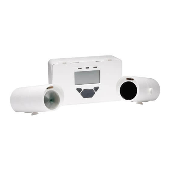
- Page 1 End To End Optical Beam Smoke Detector User Guide Document Number: 0044-047-01-EN...
-
Page 2: Table Of Contents
Contents: Page: 1. Installation 2. Commissioning 3. In Use 4. Maintenance and Troubleshooting 5. Display and Indicators 6. User Menu 7. Engineering Menu 8. Specification 9. Approval Information... -
Page 3: Installation
1. Installation 1.1 Mounting and Positioning >30cm >30cm Transmitter Receiver (Clear Lens) (Black Lens) 5 - 120m Power Controller Supply Unit • IMPORTANT NOTE: The infrared beam path MUST be kept clear of obstructions at all times! Failure to comply may result in the system initiating a Fire or Fault signal. •... -
Page 4: Wiring Diagram
1.2 Wiring Diagram For connection of Receivers to individual zones: RECEIVER 1 RECEIVER 2 TRANSMITTER TRANSMITTER OUTPUT OUTPUT SUPPLY SUPPLY 12V to 36V DC RECEIVER 2 RECEIVER 2 RECEIVER 1 RECEIVER 1 EXTERNAL FIRE FAULT FIRE FAULT N/O COM N/C N/O COM N/C RESET N/O COM N/C... - Page 5 1.3 Fitting the Product RECEIVER: TRANSMITTER: TO RECEIVER OUTPUT ON 12 to 36V DC OR CONTROLLER SUPPLY ON BOARD CONTROLLER BOARD LED indicator must face downward...
-
Page 6: Commissioning
2. Commissioning 2.1 Apply Power NOTE: One System Controller can be used to control and monitor up to two Receiver heads. The ‘#’ symbol in this guide is used to represent the number of the Receiver currently selected (1 or 2). Apply Power to Controller, Receiver(s) &... - Page 7 2.2 Enter Pass Code to Access Engineering Menu To enter PASS CODE SCREEN in USER MENU 1 2 3 4 Default Pass Code: Change digit Move between digits Accept • An incorrect Pass Code will return the display to the Pass Code entry screen •...
- Page 8 2.3 Finding Receivers • Perform 'Find' during initial installation, or when adding or removing Receivers As each Receiver is "Found" the relevant receiver number appears here This will be the number of Receivers found • Press tick to enable ‘Found’ Receivers •...
- Page 9 2.4 Select Receiver to be Accessed • All Receivers need to be aligned separately • The following sections in this User Guide explain how to align individual Receivers...
- Page 10 2.5 LASER Targeting • The LASER in the Receiver head is used to align the Receiver with the Transmitter. • The LASER can be activated using the button on the Receiver head whilst in Engineering Menu, or via the LASER icon in the ENGINEERING MENU as shown below. •...
- Page 11 2.6 Alignment Step 1 In alignment mode you are centring the Transmitter beam onto the Receiver and the system is adjusting its power for optimum signal. Step 2 NOTE 1: Value can be Set Tx power to between 2 and 178. maximum.
- Page 12 From Step 3 Step 4 NOTE 1: Value can be Adjust one between 2 and 178. thumbwheel by A higher value means a 1/4 turn. better alignment. Amber - flash/stop Green - flash/stop View LEDs on Rx or LCD value (SEE NOTE 1) (SEE NOTE 1) Signal...
- Page 13 2.7 Fire and Fault Tests • After alignment or maintenance, it is recommended that Fire and Fault tests are performed: 2.7.1 Remote Fire Test The Remote Fire Test allows the user to perform a Fire Test from the System Controller. The Remote Fire Test is acceptable for Fire Authority Acceptance and Routine Maintenance per UL 268-5.
-
Page 14: In Use
3. In Use 3.1 Settings 3.1.1 Fire Threshold This setting is the threshold at which the Receiver will detect a fire. Default factory setting=35%. (Set for each Receiver). - Page 15 3.1.2 Delay To Fire Screen This setting is the delay the System Controller uses before signalling a FIRE condition to the Fire Control Panel. Default factory setting=10 seconds. (Set for each Receiver). 3.1.3 Delay To Fault Screen This setting is the delay the System Controller uses before signalling a FAULT condition to the Fire Control Panel.
- Page 16 3.1.4 Set Fire Latching Mode Screen Default factory setting=Non-Latching (Set for each Receiver). To clear a latched fire, apply 5-40V to the External Reset terminal, enter the passcode, or power cycle for 20s. to scroll between settings in the Receiver Menu. NON-LATCHING MODE LATCHING...
-
Page 17: Maintenance And Troubleshooting
4. Maintenance and Troubleshooting 4.1 System Maintenance The system will automatically compensate for dust build-up by changing the Compensation Level. However, it is recommended that the Transmitter and Receiver lenses are cleaned periodically with a soft lint-free cloth. The system should be isolated from the Fire Control Panel before cleaning takes place. After cleaning, verify that the system is operating normally by following the Alignment procedure and the Fire and Fault Tests described in this User Guide. -
Page 18: Display And Indicators
5. Display and Indicators 5.1 LCD Icon Layout Receiver Latched / Minutes Number Compensation Reset Level Degrees Seconds User Signal & LED Fire Prompt Strength Setting Controller External Reset Setting Fault Warning Busy % / V System Locked / Address Setting Unlocked Alignment Mode Laser... -
Page 19: User Menu
6. User Menu 6.1 User Menu Overview The USER MENU allows system settings to be viewed only. The USER MENU will timeout 15 minutes after the last key press. CONTROLLER CONTROLLER SOFTWARE LED ON/OFF VERSION STATUS RECEIVED RECEIVER SIGNAL % SOFTWARE VERSION COMPENSATION... -
Page 20: Engineering Menu
7. Engineering Menu 7.1 Engineering Menu Overview The ENGINEERING MENU allows system settings to be changed. The ENGINEERING MENU will timeout 60 minutes after the last key press. RECEIVER CONTROLLER FIND SETTINGS LASER RECEIVER TARGETING SETTINGS BEAM FIRE ALIGNMENT TEST FIRE DELAY TO THRESHOLD... - Page 21 7.2 Receiver Settings 7.2.1 Receiver Settings Overview VIEW SIGNAL STRENGTH COMPENSATION SOFTWARE RX GAIN SET LATCHING HARDWARE MODE RX GAIN...
- Page 22 7.3 Controller Settings 7.3.1 Controller Settings Overview PASSCODE CHANGE SCREEN CONTROLLER STATUS LED ON/ SCREEN...
- Page 23 7.3.2 Passcode Change Screen • This screen allows the user to change the Pass Code used to access the ENGINEERING MENU. NOTE: The number being altered flashes. A partial passcode (ie. with dashes in it) will not be accepted. Default Pass Code: 1 2 3 4 Change digit Move between digits...
-
Page 24: Specification
7.3.3 Controller Status LED ON/OFF Screen This setting controls whether the System Controller Status LED will flash. Toggle ON or OFF Confirm setting Abort change 8. Specification Parameter Value Operating Range: 5 to 120m Operating Voltage Range: 12 to 36V DC +/- 10% Transmitter Current: Quiescent Current (Controller with 1 or 2 Receivers): 14mA... -
Page 25: Approval Information
9. Approval Information 9.1 UL Approval Information • UL File Number: S3417 • All installations should comply with NFPA72. No liability will be accepted for applications not conforming to NFPA regulations. Distance betweenTransmitter Fire Threshold Range and Receiver 5 - 10m (16.4 - 32.8 ft ) 10 - 20m (32.8 - 65.6 ft ) 25 - 30% 20 - 40m (65.6 - 131.2 ft )
Need help?
Do you have a question about the 3000 and is the answer not in the manual?
Questions and answers