
Related Manuals for Hapton Bay Seaport


Summary of Contents for Hapton Bay Seaport
-
Page 1: Ceiling Fan
513 349 Seaport Ceiling Fan Owner’s Manual Seaport Ventilador de Techo de 1,32 Manual del Propietario... - Page 2 Hampton Bay Seaport ®...
-
Page 3: Table Of Contents
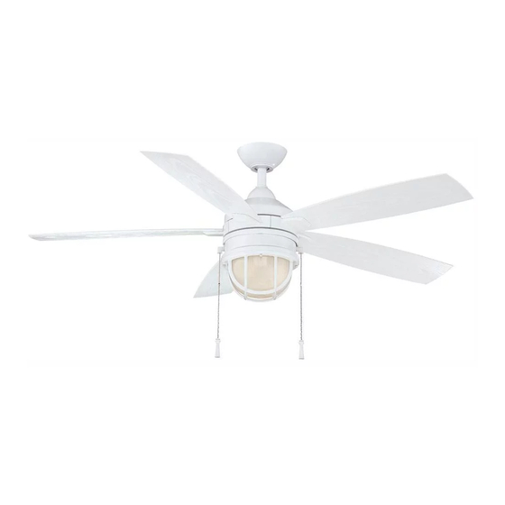
52” Seaport Thank you for purchasing our ceiling fan. This product has been manufactured with the highest standards of safety and quality. The finish of this fan is weather resistant, but over time will naturally weather and fade. Ceiling Fan by Hampton Bay... -
Page 4: Safety Rules
Safety Rules - Read and Save These Instructions To reduce the risk of electric shock, insure electricity has been turned off After making electrical connections, spliced conductors should be turned at the circuit breaker or fuse box before beginning. upward and pushed carefully up into outlet box. The wires should be spread apart with the grounded conductor and the equipment-grounding All wiring must be in accordance with the National Electrical Code conductor on one side of the outlet box and ungrounded conductor on the... -
Page 5: Unpacking Your Fan
Unpacking Your Fan Unpack your fan and check the contents. You should have the following items: Set of blades (5) Set of blade arms (5) Blade Attachment Hardware (16 Screws with Rubber Washers) Canopy assembly Mounting plate Ball/downrod assembly Light plate Electrical Hardware (3 Plastic Wire Nuts) Coupling cover... -
Page 6: Installing Your Fan
Installing Your Fan Provide Strong Support Figures 1~3 are examples of different ways to Tools Required mount the outlet box. Phillips screwdriver, straight slot screwdriver, step ladder and wire cutters. Recessed Ceiling Outlet Box Mounting Plate Figure 3 Mounting Options Outlet Box Note: You may need a longer downrod to If there isn't an existing UL listed mounting box,... -
Page 7: Hanging The Fan
Hanging the Fan Align the holes at the bottom of the downrod with the holes in the coupling on top of the Motor Wires motor housing (Figure 6). Carefully insert the REMEMBER to turn off the power. Follow the clevis pin through the holes in the collar and steps below to hang your fan properly. -
Page 8: Installing Fan To The Electrical Box
Installing Fan to the Electrical Box UL Listed WARNING Outlet Box TO REDUCE THE RISK OF FIRE, ELECTRIC 120V SHOCK OTHER PERSONAL INJURY. Ceiling Wires MOUNT FAN ONLY TO AN OUTLET BOX OR Groove SUPPORTING SYSTEM MARKED ACCEPTABLE Mounting FOR FAN SUPPORT AND USE THE MOUNTING Bracket SCREWS PROVIDED WITH THE OUTLET BOX. - Page 9 Making the Electrical Turn wire nut connections upward, spreading SUPPLY CIRCUIT them apart so the green (ground) will be on one Connections side of the outlet box and the white, black and blue wire will be on the other side, and push Ground REMEMBER to disconnect the power.
-
Page 10: Attaching The Fan Blades
Finishing the Fan Screws with Outlet Box Rubber Washers Installation Ceiling Screw Mounting Tuck connections neatly into ceiling outlet Bracket box. Canopy Blade Slide the canopy up to mounting bracket and Screw place the key hole on the canopy over the Blade Arm screw on the mounting bracket, turn canopy Canopy... - Page 11 Installing the Mounting Blade Balancing Plate The following procedure should correct most fan wobble. Check after each step. Remove 1 of 3 screws from the mounting ring and loosen the other 2 screws.(Do not remove) Check that all blade and blade arm screws are secure.
-
Page 12: Installing The Light Kit
Installing the Light Kit CAUTION the holes in the rim of the decorative frame BEFORE STARTING INSTALLATION, DISCON- with the light kit and secure using the three NECT THE POWER BY TURNING OFF THE decorative screws provided with the light kit CIRCUIT BREAKER OR REMOVING THE FUSE hardware. -
Page 13: Operating Your Fan
Operating Your Fan Turn on the power and check the operation of the Warm weather - (Counter-Clockwise direction) fan. The pull chain controls the fan speed as A downward air flow creates a cooling effect as follows: shown in Figure 16. This allows you to set your air 1 pull - High conditioner on a higher setting without affecting 2 pulls - Medium... -
Page 14: Care Of Your Fan
Care of Your Fan Troubleshooting PROBLEM SOLUTION Here are some suggestions to help you maintain your fan. Fan will not start Check main and branch circuit fuses or breakers. Because of the fan's natural movement, some Check line wire connections to the fan and switch wire connections in connections may become loose. -
Page 15: Specifications
Specifications FAN SIZE SPEED VOLTS AMPS WATTS N.W. G.W. C.F. 0.21 1891 10.18 kgs 11.21 kgs 52” MED. 1.77' 0.35 3408 (22.40 lbs) (24.66 lbs) HIGH 0.46 5020 These are approximate measures. They do not include Amps and Wattage used by the light kit. -
Page 16: Warranty Information
Hampton Bay Lifetime Limited Warranty (lifetime warranty on motor) The Hampton Bay warrants the fan motor to be free from defects in workmanship and material present at time You must present a copy of the original purchase receipt to obtain warranty of shipment from the factory for a period of lifetime after the date of purchase by the original purchaser.
Need help?
Do you have a question about the Seaport and is the answer not in the manual?
Questions and answers