Table of Contents
Advertisement
Available languages
Available languages
Quick Links
Item #610-015, 608-891
Model #51398, 51399
UL model #52-MAL
USE AND CARE GUIDE
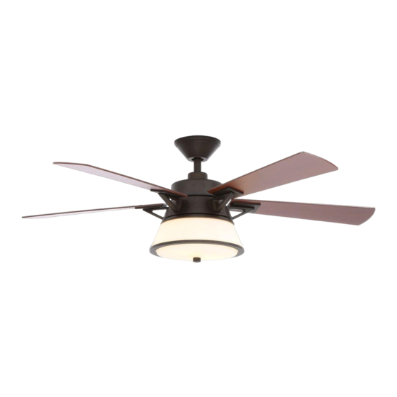
MARLOWE 52-INCH CEILING FAN
Questions, problems, missing parts? Before returning to the store,
call Hampton Bay Customer Service
8 a.m. - 6 p.m., EST, Monday-Friday.
1-877-527-0313
HAMPTONBAY.COM
THANK YOU
We appreciate the trust and confidence you have placed in Hampton Bay through the purchase of this ceiling fan. We strive to continually create
quality products designed to enhance your home. Visit us online to see our full line of products available for your home improvement needs.
Thank you for choosing Hampton Bay!
Advertisement
Chapters
Table of Contents

Subscribe to Our Youtube Channel
Related Manuals for Hapton Bay MARLOWE


Summary of Contents for Hapton Bay MARLOWE
- Page 1 Item #610-015, 608-891 Model #51398, 51399 UL model #52-MAL USE AND CARE GUIDE MARLOWE 52-INCH CEILING FAN Questions, problems, missing parts? Before returning to the store, call Hampton Bay Customer Service 8 a.m. - 6 p.m., EST, Monday-Friday. 1-877-527-0313 HAMPTONBAY.COM THANK YOU We appreciate the trust and confidence you have placed in Hampton Bay through the purchase of this ceiling fan.
-
Page 2: Table Of Contents
Table of Contents Table of Contents ..............2 Assembly ................7 Safety Information ............... 2 Operation ................13 Warranty ................3 Care and Cleaning ............. 14 Pre-Installation ..............3 Troubleshooting ..............14 Installation ................6 Safety Information All wiring must be in accordance with the National Electrical WARNING: To reduce the risk of personal injury, do Code ANSI/NFPA 70-1999 and local electrical codes. -
Page 3: Warranty
Warranty The supplier warrants the fan motor to be free from defects in workmanship and material present at time of shipment from the factory for a life- time after the date of purchase by the original purchaser. The supplier also warrants that all other fan parts, excluding any glass or acrylic blades, to be free from defects in workmanship and material at the time of shipment from the factory for a period of one year after the date of purchase by the original purchaser. -
Page 4: Hardware Included
Pre-Installation (continued) HARDWARE INCLUDED NOTE: Hardware not shown to actual size. Part Description Quantity Part Description Quantity Blade attachment screws Locking pin Plastic wire connecting nut Blade bracket screw with lockwasher Hanger pin... -
Page 5: Package Contents
Pre-Installation (continued) PACKAGE CONTENTS Part Description Quantity Part Description Quantity Slide-on mounting bracket Blade (inside canopy) Blade bracket Ball/downrod assembly Light kit fitter assembly Canopy with canopy ring attached Glass bowl Decorative motor collar cover Remote control/receiver Fan-motor assembly (batteries included) Light kit pan CFL light bulb, 14-Watt maximum IMPORTANT: This product and/or components are... -
Page 6: Installation
Installation MOUNTING OPTIONS WARNING: To reduce the risk of fire, electric shock NOTE: You may need a longer downrod to maintain or personal injury, mount to outlet box marked proper blade clearance when installing on a steep, sloped “acceptable for fan support of 35lbs. (15.9 Kg) or ceiling. -
Page 7: Assembling The Fan
Assembly - Standard Ceiling Mount Preparing for mounting Routing the wires □ □ Route the wires exiting the top of the fan motor (E) into Remove the canopy ring (O) from the canopy (C) by turning the decorative motor collar cover (D) and through the the ring to the right until it unlocks. - Page 8 Assembly - Hanging the Fan Attaching the fan to the electrical Hanging the fan WARNING: To reduce the risk of fire, electric shock □ Carefully lift the fan-motor assembly (E) up to the slide-on or personal injury, mount to outlet box marked mounting bracket (A).
-
Page 9: Assembly
Assembly - Hanging the Fan (continued) Setting the remote control codes Installing the receiver NOTE: The frequencies on your receiver and remote control have WARNING: To reduce the risk of fire or electric shock, been preset at the factory. Before installing the receiver, make remember to disconnect power. - Page 10 Assembly - Hanging the Fan (continued) Making the electrical connection Mounting the fan WARNING: Each wire nut supplied with this fan is designed to WARNING: When using the standard ball/downrod mounting, the accept up to one 12-gauge house wire and two wires from the tab in the ring at the bottom of the mounting bracket must rest in fan.
-
Page 11: Attaching The Fan Blades
Assembly - Attaching the Fan Blades Attaching the fan blades Attaching the blade assemblies □ Attach the blade assembly to the fan-motor assembly (E) NOTE: Your fan blades are reversible. Select the blade by aligning the two holes of blade bracket (H) with the two side finish which best accentuates your decor. - Page 12 Assembly - Attaching the Light Kit Attaching the light kit Attaching the light kit pan □ CAUTION: To reduce the risk of electric shock, disconnect Remove one screw (P) from the light kit pan (F). Loosen, but the electrical supply circuit to the fan before installing the do not remove the other two screws.
-
Page 13: Operation
Operation Warm weather - (Forward) A downward airflow creates a cooling ef- NOTE: The reverse switch is located at the top of motor housing. fect. This allows you to set your air conditioner on a warmer setting Shut the fan off and wait until the blades have completely stopped without affecting your comfort. -
Page 14: Care And Cleaning
Care and Cleaning WARNING: Make sure the power is off before cleaning your fan. □ Because of the fan’s natural movement, some connections may become loose. Check the support connections, brackets, and blade attachments twice a year. Make sure they are secure. It is not necessary to remove the fan from the ceiling. □... - Page 15 Questions, problems, missing parts? Before returning to the store, call Hampton Bay Customer Service 8 a.m. - 6 p.m., EST, Monday-Friday 1-877-527-0313 HAMPTONBAY.COM Retain this manual for future use.
- Page 16 Modelo Núm. 52-MAL Aprobado por UL GUÍA DE USO Y MANTENIMIENTO VENTILADOR DE TECHO MARLOWE, DE 52 PLG (1,32 M) ¿Preguntas, problemas o piezas faltantes? Antes de regresar a la tienda, llama al Servicio al Cliente de Hampton Bay de Lunes a Viernes entre 8 a.m. y 6 p.m., (Hora del Este de EE. UU.) 1-877-527-0313 HAMPTONBAY.COM...
- Page 17 Tabla de Contenido Tabla de Contenido ............. 2 Ensamblaje ................7 Información de Seguridad ..........2 Funcionamiento ..............13 Garantía ................3 Mantenimiento y Limpieza..........14 Preinstalación ..............3 Solución de Problemas ............. 14 Instalación ................6 Información de Seguridad Todo el cableado debe cumplir con el Código Nacional ADVERTENCIA: Para reducir el riesgo de lesiones de Electricidad ANSI/NFPA 70-1999 y con los códigos locales...
-
Page 18: Garantía
Garantía A partir de la fecha de compra por el comprador original, el proveedor garantiza de por vida, que el motor del ventilador no presenta defectos de fabricación ni de material desde la fecha de salida de la fábrica. El proveedor también garantiza por un período de un año, a partir de la fecha de compra por el comprador original, que todas las demás piezas del ventilador, sin incluir ningún aspa de vidrio o acrílico, no presentarán ningún defecto de fabricación o de material en el momento de su salida de la fábrica. - Page 19 Preinstalación (continuación) HERRAJES INCLUIDOS NOTA: No se muestra el tamaño real de los herrajes. Pieza Descripción Cantidad Pieza Descripción Cantidad Tornillos para el montaje de aspas Pasador de cierre Tuerca de plástico para conectar Tornillo adicional para soporte de cables aspas con contratuerca Pasador de soporte...
-
Page 20: Contenido Del Paquete
Preinstalación (continuación) CONTENIDO DEL PAQUETE Pieza Descripción Cantidad Pieza Descripción Cantidad Soporte de montaje deslizante Aspa (dentro de la cubierta) Soporte de aspa Ensamblaje de tubo bajante/bola Ensamblaje del soporte del kit de Cubierta con aro incorporado luces Cubierta decorativa del collarín del Tazón de vidrio motor Control remoto/receptor... -
Page 21: Instalación
Instalación OPCIONES DE MONTAJE NOTA: Tal vez necesites un tubo bajante más largo para ADVERTENCIA: Para reducir el riesgo de incendio, descarga eléctrica o lesiones personales, monta el ventilador sobre una caja eléctrica mantener la altura mínima adecuada de las aspas, al marcada como “aprobada como soporte de ventiladores de 35 lb (15,9 instalar el ventilador en un techo inclinado. - Page 22 Ensamblaje – Montaje Estándar en Techo Preparación para el montaje Disposición de los cables □ □ Inserta los cables que salen por la parte superior del Retira el aro (O) de la cubierta (C), girándolo hacia la derecha motor del ventilador (E) en la cubierta decorativa del hasta soltarlo.
- Page 23 Ensamblaje – Cómo Colgar el Ventilador Cómo fijar el ventilador Cómo colgar el ventilador a la caja eléctrica □ Con cuidado alza el ensamblaje del motor del ventilador (E) ADVERTENCIA: Para reducir el riesgo de incendio, hasta el soporte de montaje deslizante (A). descarga eléctrica o lesiones personales, monta el □...
-
Page 24: Ensamblaje
Ensamblaje – Cómo Colgar el Ventilador (continuación) Cómo configurar los códigos Cómo instalar el receptor del control remoto ADVERTENCIA: Para reducir el riesgo de incendio o de descarga NOTA: Las frecuencias del receptor y control remoto han sido eléctrica, recuerda desconectar la electricidad. El cableado preconfiguradas en la fábrica. - Page 25 Ensamblaje – Cómo Colgar el Ventilador (continuación) Cómo hacer las conexiones eléctricas Cómo montar el ventilador ADVERTENCIA: Cada cable no suministrado con este ventilador está ADVERTENCIA: Cuando uses el ensamblaje del tubo bajante/ diseñado para aceptar hasta un circuito eléctrico de casa de calibre bola estándar, la pestaña en el aro en la parte inferior del soporte 12 y dos cables del ventilador.
- Page 26 Ensamblaje – Cómo Unir las Aspas del Ventilador Cómo unir las aspas del ventilador Cómo montar las aspas ensambladas NOTA:Las aspas de tu ventilador son reversibles. Elige □ Coloca el aspa en la carcasa del motor del ventilador (E) el acabado del aspa que mejor resalte tu decoración. alineando los dos orificios del soporte del aspa (H) con los dos □...
- Page 27 Ensamblaje – Cómo Instalar el Kit de Luces Cómo instalar el kit de luces Cómo instalar la carcasa del kit de luces □ Quita un tornillo (P) de la carcasa del kit de luces (F). Afloja los PRECAUCIÓN: Para disminuir el riesgo de descarga eléctrica, otros dos tornillos, sin quitarlos.
-
Page 28: Funcionamiento
Funcionamiento Clima cálido - (Hacia adelante) Un flujo de aire descendente crea un NOTA: El interruptor de reversa está ubicado en la superficie de efecto de enfriamiento. Esto te permite fijar tu aire acondicionado en la carcasa del motor. Apaga el ventilador y espera hasta que las una configuración más alta sin afectar tu comodidad. -
Page 29: Mantenimiento Y Limpieza
Mantenimiento y limpieza ADVERTENCIA: Asegúrate de que la corriente esté apagada antes de limpiar el ventilador. □ Debido al movimiento natural del ventilador, algunas conexiones pueden aflojarse. Revisa las conexiones de soporte, soportes y accesorios de aspas dos veces al año. Verifica que estén seguros. No es necesario desmontar el ventilador del techo. □... - Page 30 ¿Preguntas, problemas o piezas faltantes? Antes de regresar a la tienda, llama al Servicio al Cliente de Hampton Bay de Lunes a Viernes entre 8 a.m. y 6 p.m., (Hora del Este de EE. UU.) 1-877-527-0313 HAMPTONBAY.COM Conserva este manual para uso en el futuro.
Need help?
Do you have a question about the MARLOWE and is the answer not in the manual?
Questions and answers